Overcoming Mass Transport Limitations in Porous Electrodes: Advanced Strategies for Biosensors, Batteries, and Drug Delivery
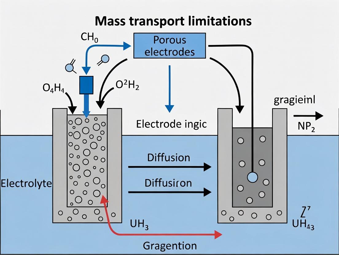
Mass transport limitations within porous electrodes represent a critical bottleneck across electrochemical technologies, from enzymatic biosensors to next-generation batteries and electrochemically-triggered drug delivery systems.
Overcoming Mass Transport Limitations in Porous Electrodes: Advanced Strategies for Biosensors, Batteries, and Drug Delivery
Abstract
Mass transport limitations within porous electrodes represent a critical bottleneck across electrochemical technologies, from enzymatic biosensors to next-generation batteries and electrochemically-triggered drug delivery systems. This article provides a comprehensive, multi-perspective analysis tailored for researchers and biomedical engineers. We first establish the foundational physics of transport phenomena—diffusion, migration, and convection—within complex porous networks. We then explore cutting-edge methodological approaches for electrode design and fabrication, including engineered porosity, 3D printing, and nano-structuring. A dedicated troubleshooting section addresses common challenges such as pore clogging and uneven reaction distribution, offering optimization protocols. Finally, we critically compare and validate performance metrics through computational modeling and experimental characterization techniques. This synthesis aims to equip professionals with a holistic framework to design high-performance porous electrodes that overcome transport barriers for enhanced sensitivity, power density, and controlled release kinetics.
The Physics of Pore-Scale Transport: Unraveling Diffusion, Convection, and Reaction in Confined Spaces
Technical Support Center: Troubleshooting Mass Transport in Porous Electrodes
FAQs & Troubleshooting Guides
Q1: My measured electrode ionic conductivity is consistently lower than theoretical predictions from bulk electrolyte properties. What are the primary porous structure culprits? A: This is a classic sign of mass transport limitation within the electrode's pore network. The discrepancy is governed by three key microstructural parameters:
- Porosity (ε): A low effective porosity reduces the volume available for ion transport.
- Tortuosity (τ): A high tortuosity forces ions to follow longer, winding paths, drastically reducing effective diffusivity and conductivity.
- Pore Size Distribution (PSD): A distribution skewed towards very small pores (e.g., < 2 nm) increases viscous drag and surface interactions, further hindering flow.
Solution: Characterize your electrode's microstructure. Use mercury intrusion porosimetry (MIP) or gas physisorption (BET/BJH) for PSD and porosity. Calculate tortuosity via the Bruggeman relation (τ = ε^(-0.5)) as a first approximation, or use more advanced methods like electrochemical impedance spectroscopy (EIS) to measure it directly.
Q2: When performing cyclic voltammetry on my porous film, I observe peak separation increasing with scan rate, indicating diffusion limitations. How do I decouple the effects of pore size vs. tortuosity? A: Peak separation (ΔEp) is sensitive to the effective diffusion coefficient (Deff), where Deff = (ε/τ) * D_bulk. To decouple:
- Design a controlled experiment: Fabricate a series of electrodes with similar porosity but different pore architectures (e.g., by using different pore-forming agents).
- Measure τ independently: Use a symmetric cell configuration with a blocking electrolyte and perform EIS. The high-frequency resistance relates to ionic conductivity, from which τ can be extracted if ε is known.
- Correlate with PSD: Analyze the PSD from your characterization. A system with a narrow PSD at a larger mean size but high ΔEp points to high tortuosity as the dominant factor.
Experimental Protocol: EIS for Tortuosity Measurement
- Cell Assembly: Construct a symmetric cell: Cu Current Collector | Porous Electrode | Electrolyte | Porous Electrode | Cu Current Collector. Use a non-Faradaic, blocking electrolyte (e.g., 1M LiTFSI in propylene carbonate).
- EIS Setup: Apply a sine wave with 10 mV amplitude over a frequency range of 1 MHz to 0.1 Hz.
- Data Analysis: In the Nyquist plot, the high-frequency real-axis intercept corresponds to the total ionic resistance (R_ion) of the porous medium.
- Calculation: Use the relation: τ = (Rion * A * ε * κbulk) / L, where A is electrode area, L is thickness, and κ_bulk is the bulk electrolyte conductivity.
Q3: I am observing non-uniform reaction product deposition (e.g., Li plating, catalyst poisoning) only in the center of my thick porous electrode. What structural factors cause this? A: This is a direct result of poor mass transport leading to reactant depletion in the electrode interior. The governing equation for steady-state flux highlights the role of structure: J ∝ (ε * D_bulk * ΔC) / (τ * L) Where L is the electrode thickness. A combination of low porosity (ε), high tortuosity (τ), and large thickness (L) will steepen the concentration gradient (ΔC), causing the reaction to be confined to the electrode surface facing the electrolyte, leaving the center inactive or prone to side reactions.
Solution: Engineer a hierarchical pore structure. Introduce larger macropores (low tortuosity channels) to facilitate bulk transport to the interior, while maintaining mesopores (high surface area) for reaction sites. Consider gradient porosity designs.
Q4: My gas diffusion electrode (GDE) floods at high current densities, collapsing performance. How do pore size distribution and wetting properties interact? A: Flooding is a capillary pressure issue dictated by the Young-Laplace equation: P_cap ∝ γ cos(θ) / r, where r is the pore radius.
- Problem: An abundance of small hydrophilic pores (small r, cos(θ) > 0) will draw liquid electrolyte in via capillary action, displacing the gas phase (flooding).
- Solution: Tailor the Pore Size Distribution and wettability (contact angle θ). Create a hydrophobic macroporous layer (large r, cos(θ) < 0) to allow gas permeation and prevent liquid ingress, backed by a mesoporous reaction layer. Use PTFE or PVDF as hydrophobic binders.
Table 1: Typical Ranges and Impact of Porous Electrode Parameters
| Parameter | Symbol | Typical Range (Fuel Cells/Batteries) | Governing Relation (Mass Transport) | Primary Impact |
|---|---|---|---|---|
| Porosity | ε | 0.3 - 0.8 | Volume fraction for transport | Limits active site density & transport volume. |
| Tortuosity | τ | 2 - 10+ | Deff = (ε/τ) * Dbulk | Reduces effective diffusivity/conductivity. |
| Mean Pore Size | r_mean | 10 nm - 50 μm | Knudsen number, Capillary pressure | Dictates transport regime & wetting behavior. |
| Pore Size Distribution | PSD | Multimodal is often ideal | -- | Balances high surface area (small pores) vs. low-tortuosity pathways (large pores). |
Table 2: Common Characterization Techniques for Porous Electrodes
| Technique | Measures | Sample Requirement | Key Output for Transport |
|---|---|---|---|
| Mercury Intrusion Porosimetry (MIP) | Pore size distribution (macropores), porosity, pore volume. | Dry, solid. | PSD curve, total pore volume, median pore diameter. |
| Gas Physisorption (BET/BJH) | Surface area, pore size distribution (micropores/mesopores). | Dry, degassed. | BET surface area, mesopore PSD. |
| Electrochemical Impedance Spectroscopy (EIS) | Ionic resistance, charge transfer resistance. | Assembled cell with electrolyte. | Direct measurement of effective ionic conductivity & tortuosity. |
| X-ray Computed Tomography (XCT) | 3D microstructure, tortuosity factor, connectivity. | Small sample (<1 mm). | 3D reconstruction for direct τ calculation and visualization. |
The Scientist's Toolkit: Research Reagent Solutions
Table 3: Essential Materials for Fabricating & Analyzing Porous Electrodes
| Item | Function | Example & Notes |
|---|---|---|
| Pore-Forming Agents | Create controlled porosity during electrode fabrication. | NH4HCO3, PMMA microspheres: Decompose/combust to leave pores. SiO2 nanoparticles: Can be etched with HF. |
| Conductive Additives | Enhance electronic conductivity in composite electrodes. | Carbon Black (Super P, Ketjenblack), Carbon Nanotubes (CNTs): Form conductive percolation network. |
| Hydrophobic Agents | Control wetting properties in GDEs or prevent flooding. | Polytetrafluoroethylene (PTFE) dispersion, Polyvinylidene fluoride (PVDF): Create water-repellent surfaces. |
| Binder | Hold active material and conductive network together. | Nafion (ionomer for PEMs), PVDF, CMC/SBR: Choice affects ionic access and mechanical stability. |
| Blocking Electrolyte | For EIS-based tortuosity measurement. | 1M LiTFSI in Propylene Carbonate: Non-reactive, allows measurement of pure ionic resistance. |
Mass Transport Limitation Analysis Workflow
Diagram Title: Porous Electrode Mass Transport Diagnosis Tree
Troubleshooting Guides & FAQs
Fickian & Knudsen Diffusion
Q1: Our measured diffusion coefficient in a porous electrode is significantly lower than the theoretical bulk value. What could be the cause? A: This is a classic sign of Knudsen diffusion dominance or hindered diffusion. First, calculate the Knudsen number (Kn = λ / dpore). If Kn > 1, Knudsen diffusion, where molecules collide more with pore walls than with each other, is limiting. For mesopores (2-50 nm), this is common. Ensure your model uses an effective diffusion coefficient: Deff = (ε/τ) * D, where ε is porosity and τ is tortuosity. Also, verify your pore size distribution data; an unexpected abundance of micropores (<2 nm) can cause severe mass transport limitations.
Q2: How do we distinguish between Fickian and non-Fickian (anomalous) diffusion in our experimental release kinetics data? A: Fit your drug release or ion uptake data to the power-law model: Mt / M∞ = k * t^n. Plot log(Mt/M∞) vs. log(t). A slope (n) of 0.5 indicates Fickian diffusion (case I). A slope between 0.5 and 1.0 indicates anomalous diffusion (non-Fickian, case II), often due to polymer swelling or pore structure changes. A slope of 1.0 indicates zero-order, relaxation-controlled transport. Knudsen-dominated processes typically remain Fickian but with a reduced apparent D.
Electromigration & Electroosmotic Flow (EOF)
Q3: Our EOF-driven delivery experiment shows inconsistent flow rates at constant applied voltage. What should we check? A: Inconsistent EOF often points to changes in zeta potential (ζ) at the pore walls. Troubleshoot as follows:
- pH Control: Measure and actively buffer the electrolyte pH. ζ is highly pH-dependent, especially for silica or oxide-based materials.
- Ion Contamination: Replace electrolytes with fresh, high-purity solutions. Adsorption of polyvalent ions can screen surface charge.
- Clogging: Perform a post-experiment pore size analysis (e.g., porosimetry) to check for blockage.
- Electrode Reactions: Ensure your electrodes are stable and separated by a membrane if necessary. Gas bubble formation at electrodes can interrupt the circuit and flow.
Q4: During electromigration, we observe pH fronts moving through our porous electrode, disrupting the experiment. How can we mitigate this? A: This is caused by water electrolysis at the electrodes (H⁺ generated at anode, OH⁻ at cathode). To mitigate:
- Use high buffer capacity (≥ 50 mM) appropriate for your pH range.
- Increase the distance between driving electrodes and your porous sample, or use agar salt bridges.
- Consider using redox-coupled electrolytes or reversible electrodes to minimize water splitting.
Data Tables
Table 1: Dominant Transport Regimes by Pore Scale
| Pore Diameter (d) | Knudsen Number (Kn) | Dominant Transport Mechanism | Typical Experimental Signature |
|---|---|---|---|
| Macropores (> 50 nm) | Kn < 0.01 | Fickian (Bulk) Diffusion | Deff ≈ Dbulk; Linear Fickian kinetics. |
| Mesopores (2 - 50 nm) | 0.01 < Kn < 1 | Transitional Diffusion | Deff < Dbulk; Strong dependence on pore size. |
| Micropores (< 2 nm) | Kn > 1 | Knudsen Diffusion / Surface Diffusion | Very low D_eff; Uptake scales with (T/M)^0.5. |
| Charged Pores (Any, with field) | N/A | Electromigration & EOF | Flow proportional to ζ-potential and V; pH-sensitive. |
Table 2: Key Parameters for Quantitative Analysis
| Parameter | Symbol | Typical Measurement Technique | Impact on Transport |
|---|---|---|---|
| Porosity | ε | Mercury Intrusion Porosimetry (MIP), Micro-CT | Directly scales flux: J ∝ ε. |
| Tortuosity | τ | Electrochemical Impedance Spectroscopy (EIS), MIP | Reduces flux: J ∝ 1/τ. Critical in Bruggeman correction (τ = ε^−0.5). |
| Zeta Potential | ζ | Electrokinetic Analysis, Streaming Potential | Drives EOF velocity: uEOF = (εr ε_0 ζ / μ) E. |
| Effective Diffusivity | D_eff | Time-Lag Experiment, Uptake Kinetics, EIS | Deff = (ε/τ) * Dbulk (for Fickian). |
Experimental Protocols
Protocol 1: Determining Dominant Diffusion Mechanism in a Porous Electrode
Objective: To experimentally distinguish between Fickian bulk diffusion and Knudsen diffusion as the rate-limiting step. Materials: Porous electrode sample, diffusion cell (two compartments), analyte of interest (e.g., a drug molecule, redox probe), HPLC or UV-Vis spectrometer, conductivity/pH meter. Method:
- Saturate the porous electrode with the chosen background electrolyte. Ensure no air bubbles are trapped.
- Mount the electrode as a separating membrane between the two compartments of the diffusion cell.
- Fill the donor compartment with a known concentration (C₀) of the analyte. Fill the receiver compartment with pure electrolyte.
- Gently stir both compartments to eliminate boundary layer effects.
- At regular intervals, sample a small volume from the receiver compartment and analyze analyte concentration (C_t) via HPLC/UV-Vis.
- Plot the cumulative transported mass (M_t) versus time (t).
- Analysis: Fit the initial linear portion of Mt vs t. The slope is the steady-state flux, J. Calculate the experimental diffusivity: Dexp = (J * L) / (ε * ΔC), where L is thickness, ΔC is concentration difference. Compare Dexp to the theoretical bulk diffusivity (Dbulk) of the analyte. If Dexp << Dbulk and your pore size data confirms meso/micropores, Knudsen diffusion is likely dominant.
Protocol 2: Characterizing Electroosmotic Flow (EOF) in a Porous Membrane
Objective: To measure the magnitude and direction of EOF generated across a charged porous material. Materials: Charged porous membrane, U-shaped capillary flow cell, platinum wire electrodes, high-voltage power supply, microscope with camera, fluorescent tracer particles. Method:
- Assemble the flow cell with the porous membrane vertically separating two electrolyte reservoirs.
- Fill the system with a well-defined electrolyte (specify ionic strength and pH).
- Introduce a dilute suspension of fluorescent tracer particles into one reservoir.
- Focus the microscope on a clear channel or pore opening on one side of the membrane.
- Apply a constant electric field (e.g., 50 V/cm) across the membrane using the Pt electrodes.
- Record a video of the tracer particles near the pore opening.
- Use particle tracking software to determine the velocity (u_EOF) of the particles.
- Analysis: The direction of flow indicates the sign of the surface charge. EOF velocity is given by: uEOF = μEOF * E, where μEOF is the electroosmotic mobility. Calculate the apparent zeta potential using the Helmholtz-Smoluchowski equation: ζ = (μEOF * μ) / (εr ε0), where μ is viscosity, εr ε0 is permittivity.
Diagrams
Title: Decision Tree for Diagnosing Transport Mechanisms
Title: Workflow for Measuring Effective Diffusivity
The Scientist's Toolkit: Research Reagent Solutions
| Item | Function & Relevance |
|---|---|
| Potassium Ferricyanide/Ferrocyanide (K₃Fe(CN)₆ / K₄Fe(CN)₆) | Standard redox probe for electrochemical diffusivity measurements (EIS, CV). Inert, well-defined electrochemistry allows calculation of D_eff via Randles-Ševčík equation. |
| Fluorescein or Rhodamine B Tracers | Fluorescent dyes for visualizing and quantifying fluid flow and dispersion in porous networks, especially useful for confirming EOF. |
| Polystyrene Nanospheres (e.g., 100 nm) | Size-calibrated particles for probing pore accessibility, assessing pore clogging, and as tracers for particle image velocimetry (PIV) of EOF. |
| pH Buffers (e.g., Phosphate, MES, HEPES) | Critical for stabilizing zeta potential (ζ) at pore surfaces. Uncontrolled pH drift alters EOF direction and magnitude, ruining reproducibility. |
| Quaternary Ammonium Salts (e.g., CTAB) or SDS | Surfactants used to deliberately modify the surface charge (and thus ζ) of porous materials to study its impact on EOF and adsorption. |
| High Surface Area Carbon (e.g., Vulcan XC-72, Activated Carbon) | Common model porous electrode materials with tunable properties for foundational mass transport studies. |
| Ionic Liquids (e.g., [BMIM][BF₄]) | Low-vapor-pressure electrolytes for studies in non-aqueous systems or to minimize gas bubble formation during high-voltage electromigration. |
| Agarose Salt Bridges | Used to separate electrode chambers from main cell, preventing pH front migration and bubble interference in electromigration/EOF experiments. |
Technical Support Center: Troubleshooting & FAQs
Q1: My measured current plateau is significantly lower than the theoretical kinetic current predicted by the Butler-Volmer equation. What is the primary cause and how can I confirm it?
A1: This is a classic symptom of mass transport limitation. The Butler-Volmer equation describes current as a function of overpotential under kinetic control. When the reaction rate at the electrode surface depletes reactant concentration faster than it can be replenished by diffusion or convection, a mass transport-limited current plateau is observed.
- Troubleshooting Steps:
- Vary Stirring Rate/Flow Rate: In a rotating disk electrode (RDE) or flow cell system, increase the rotation speed or flow rate. If the plateau current increases, it confirms mass transport limitation.
- Concentration Dependence: Perform experiments at different bulk reactant concentrations. The limiting current should scale linearly with concentration if transport-limited.
- Potential Scan Rate (CV): In cyclic voltammetry, increase the scan rate. If the peak current increases linearly with the square root of scan rate (Randles-Ševčík behavior), it indicates diffusion control.
Q2: When using a porous electrode for sensing, my signal decays rapidly over time. How do I diagnose if this is due to pore clogging versus a reaction kinetics issue?
A2: Signal decay in porous electrodes often stems from hindered mass transport.
- Diagnostic Protocol:
- Pre- and Post-Experiment Microscopy: Use SEM to compare pore structure before and after experiment. Visible debris or structural change indicates fouling/clogging.
- Electrochemical Impedance Spectroscopy (EIS): Track changes in the low-frequency Warburg element (associated with diffusion) and series resistance over time. A large increase in Warburg coefficient suggests worsening mass transport.
- Control Experiment with a Redox Probe: Test the electrode with a simple, well-understood redox couple (e.g., Ferri/Ferrocyanide) before and after your main experiment. A decreased signal for the probe strongly suggests physical clogging or passivation, not specific reaction kinetics.
Q3: How do I decouple the charge transfer kinetics (Butler-Volmer) from mass transport effects in my experimental data?
A3: Use a combination of techniques to isolate the kinetic current (ik).
- Detailed Methodology (Koutecký-Levich Analysis for RDE):
- Perform experiments at a fixed potential across a range of rotation rates (ω, in rpm or rad/s).
- Measure the limiting current (ilim) at each ω.
- Plot the inverse of the current (1/i) versus the inverse of the square root of rotation rate (1/ω1/2).
- The y-intercept of the linear fit corresponds to 1/ik, the pure kinetic current, free from mass transport influence.
Q4: My simulations show a discrepancy between modeled and experimental polarization curves for my porous electrode. Where should I start checking my coupling parameters?
A4: Focus on the parameters that bridge the Butler-Volmer kinetics to transport.
- Priority Check List:
- Effective Diffusion Coefficient (Deff): This is often
D<sub>bulk</sub> * (Porosity / Tortuosity). Verify your porosity and tortuosity estimates (often from microscopy or Bruggeman correlation). - Active Surface Area: The electrochemically active surface area (ECSA) used in the Butler-Volmer current density must be accurate, not the geometric area. Measure via double-layer capacitance or underpotential deposition.
- Local Concentration in the Pore: Ensure your model correctly solves for
c<sub>surface</sub>at each point in the pore, which is used as the input concentration for the Butler-Volmer equation, not the bulk concentration.
- Effective Diffusion Coefficient (Deff): This is often
Table 1: Common Redox Probes for Diagnosing Mass Transport & Kinetics
| Redox Couple | Standard Potential (V vs. SHE) | Diffusivity (D, cm²/s) | Primary Use in Troubleshooting |
|---|---|---|---|
| Ferri/Ferrocyanide [Fe(CN)₆]³⁻/⁴⁻ | +0.36 | ~6.5 x 10⁻⁶ | Testing electrode activity, clogging, and heterogeneous electron transfer kinetics. |
| Ru(NH₃)₆³⁺/²⁺ | -0.16 | ~8.1 x 10⁻⁶ | Kinetics relatively insensitive to electrode material and surface state. Good for mass transport studies. |
| Hydroquinone / Benzoquinone | +0.28 | ~7.0 x 10⁻⁶ | Studying reactions involving protons (coupled H⁺ transfer). |
Table 2: Experimental Signatures of Rate-Limiting Steps
| Observation (Cyclic Voltammetry) | Likely Rate-Limiting Step | Diagnostic Test |
|---|---|---|
| Peak current (ip) ∝ √(scan rate) | Mass Transport (Diffusion) | Perform at different scan rates. |
| Peak potential (Ep) shifts with scan rate | Charge Transfer Kinetics | Analyze Tafel plot at low overpotential. |
| Asymmetric peak heights (ipc/ipa ≠ 1) | Coupled chemical reaction (EC, CE) | Vary scan rate; simulate mechanism. |
| Current plateau, independent of scan rate | Mass Transport (Convection) or Surface Confinement | Use RDE or vary stirring. |
Experimental Protocols
Protocol 1: Rotating Disk Electrode (RDE) for Determining Kinetic Current Objective: Decouple kinetic current from mass transport for a dissolved reactant. Steps:
- Setup: Use a standard 3-electrode cell with a polished glassy carbon RDE, Pt counter electrode, and stable reference electrode (e.g., Ag/AgCl).
- Purging: Sparge electrolyte with inert gas (N₂, Ar) for at least 20 minutes to remove oxygen.
- Background Scan: Record a CV in the potential window of interest in pure electrolyte.
- Analyte Addition: Introduce the reactant at a known concentration.
- Rotation Series: At a fixed potential within the reaction zone, record steady-state current at minimum 5 different rotation rates (e.g., 400, 900, 1600, 2500, 3600 rpm).
- Koutecký-Levich Analysis: Plot
1/i vs. 1/ω¹ᐟ². The linear fit yields the kinetic current from the intercept.
Protocol 2: EIS for Probing Porous Electrode Transport Parameters Objective: Characterize charge transfer resistance and mass transport resistance within a porous film. Steps:
- Biasing: Hold the electrode at the DC potential where the reaction occurs.
- AC Perturbation: Apply a sinusoidal potential wave with a small amplitude (typically 10 mV) over a wide frequency range (e.g., 100 kHz to 10 mHz).
- Data Acquisition: Measure the impedance (magnitude and phase) at each frequency.
- Model Fitting: Fit the Nyquist plot to an equivalent circuit. For porous electrodes, use a model incorporating:
- Solution resistance (Rs)
- Pore distributed resistance and capacitance (Transmission Line model elements)
- Charge Transfer Resistance (Rct) from Butler-Volmer kinetics
- Finite-length Warburg element (WO) for diffusion in pores.
The Scientist's Toolkit: Research Reagent Solutions
Table 3: Essential Materials for Coupled Kinetics-Transport Experiments
| Item | Function/Description |
|---|---|
| Rotating Disk Electrode (RDE) Setup | Imposes controlled, uniform convection to the electrode surface, allowing quantitative separation of kinetics and mass transport via the Levich and Koutecký-Levich equations. |
| High-Purity, Fast Redox Probes (e.g., 1-10 mM Potassium Ferricyanide) | Well-characterized, reversible couples used to benchmark electrode performance, measure active surface area, and test for transport obstructions. |
| Porous Electrode Substrates (e.g., Glassy Carbon Foam, Carbon Felt, Templated Metal Foams) | High-surface-area supports that intrinsically introduce complex mass transport pathways, essential for studying real-world device conditions. |
| Potentiostat with EIS Capability | Instrument required to apply controlled potentials/currents and measure response. EIS is critical for deconvoluting resistive and capacitive contributions in porous systems. |
| Digital Simulation Software (e.g., COMSOL, DigiElch) | Used to solve coupled partial differential equations (Fick's law for diffusion + Butler-Volmer boundary condition) to model behavior in porous electrodes and fit experimental data. |
Visualization: Workflows and Relationships
Title: Troubleshooting Flow for Kinetics vs Transport Issues
Title: Coupling of Transport and Kinetics in a Pore
Technical Support Center
Welcome to the Technical Support Center for the Porous Electrode Transport Limitation Research Consortium (PETRC). This resource provides troubleshooting and FAQs for common experimental challenges in biosensor and battery research linked to mass transport constraints.
Troubleshooting Guide & FAQs
Q1: My amperometric biosensor shows a rapidly decaying current signal after initial sample injection, followed by a low, unstable signal. What is the cause and solution? A: This is a classic symptom of analyte depletion within the electrode's diffusion layer, exacerbated by poor convective mixing.
- Primary Cause: Mass transport limitation of the target analyte (e.g., glucose, neurotransmitter) to the immobilized enzyme/recognition layer. The reaction kinetics at the electrode surface are faster than the rate of analyte supply.
- Troubleshooting Steps:
- Verify Flow/Stirring: Ensure consistent, calibrated stirring or flow rates in your experimental setup. Refer to Table 1 for recommended parameters.
- Check Electrode Porosity: Use BET surface area analysis to confirm your porous electrode structure has not collapsed or fouled, reducing effective surface area.
- Protocol - Limiting Current Test: Perform a experiment where you incrementally increase stirring speed or flow rate while measuring the steady-state current for a fixed analyte concentration. Plot current vs. (stirring rate)^(1/2) or flow rate. If the current plateaus, surface kinetics are no longer limiting; if it continuously rises, mass transport is the dominant limitation.
Q2: My battery cell exhibits a significant voltage drop (polarization) under high discharge rates, leading to poor power density despite using high-capacity active materials. A: This "rate capability" failure is often due to ionic transport limitations within the porous electrode.
- Primary Cause: Slow diffusion of Li+/Na+ ions within the electrolyte-filled pores of the thick electrode, especially at high C-rates. This creates a concentration gradient and overpotential.
- Troubleshooting Steps:
- Analyze Electrode Architecture: Review electrode composition (active material, binder, conductive additive ratios) and thickness. Excessively thick electrodes (>100 µm) often have severe transport issues.
- Measure Ionic Conductivity: Use electrochemical impedance spectroscopy (EIS) to separate the charge transfer resistance from the Warburg diffusion element. A large low-frequency Warburg tail indicates diffusion limitations.
- Protocol - Rate Performance Analysis: Cycle your cell at incrementally higher C-rates (e.g., 0.1C, 0.5C, 1C, 2C, 5C). Calculate and compare the capacity retention at each rate. A sharp drop-off points to transport issues. See Table 2 for data structure.
Q3: In my immunoassay on a porous electrochemical platform, the signal saturates at a much lower analyte concentration than theoretical, reducing dynamic range and sensitivity. A: This is typically due to the "hook effect" combined with transport limitations of capture antibodies or analytes within the deep pores.
- Primary Cause: In porous networks, the outer regions of the pore can become saturated with captured analyte, preventing it from reaching and saturating recognition sites deeper within the structure. This leads to an early signal plateau.
- Troubleshooting Steps:
- Optimize Incubation Time & Flow: Implement flow-through or rocking during incubation to enhance convective delivery into pores. Systematically vary incubation time to find the point where signal no longer increases.
- Modify Pore Surface Chemistry: Ensure your surface functionalization protocol (e.g., for antibody immobilization) is uniform throughout the pore depth. Consider using smaller recognition elements (e.g., nanobodies, aptamers) for better pore penetration.
- Protocol - Spatial Profiling: Use a technique like confocal microscopy with fluorescently labeled analytes to visually confirm if binding is uniform throughout the electrode cross-section or only on the top surface.
Table 1: Biosensor Performance Under Varied Transport Conditions
| Analyte | Electrode Type | Stirring Rate (RPM) | Measured Current (µA) | Theoretical Kinetic Current (µA) | Transport Efficiency (%) |
|---|---|---|---|---|---|
| Glucose | Carbon Felt, 500 µm | 0 | 1.2 | 10.5 | 11.4 |
| Glucose | Carbon Felt, 500 µm | 500 | 6.8 | 10.5 | 64.8 |
| Glucose | Carbon Felt, 500 µm | 1000 | 9.1 | 10.5 | 86.7 |
| H₂O₂ | Sputtered Au, planar | 0 | 8.9 | 9.0 | 98.9 |
Table 2: Battery Rate Capability vs. Electrode Design
| Active Material | Electrode Thickness (µm) | Porosity (%) | Capacity at 0.1C (mAh/g) | Capacity at 2C (mAh/g) | Rate Retention (%) |
|---|---|---|---|---|---|
| NMC-811 | 50 | 30 | 200 | 185 | 92.5 |
| NMC-811 | 100 | 30 | 195 | 150 | 76.9 |
| NMC-811 | 100 | 40 | 190 | 165 | 86.8 |
| LFP | 120 | 35 | 165 | 155 | 93.9 |
Experimental Protocols
Protocol 1: Rotating Disk Electrode (RDE) Analysis for Biosensor Transport Characterization Objective: To decouple kinetic current from mass-transport-limited current.
- Fabrication: Drop-cast your biocatalytic layer (e.g., enzyme + Nafion) onto a polished glassy carbon RDE tip. Dry under ambient conditions.
- Setup: Assemble a standard 3-electrode cell in buffer with the RDE as working electrode. Connect to a potentiostat with a rotation speed controller.
- Measurement: In a solution containing your analyte, apply the relevant fixed potential. Record amperometric i-t response.
- Data Acquisition: Step the rotation speed through a series (e.g., 400, 900, 1600, 2500 RPM). Record the steady-state current at each speed.
- Analysis: Plot current (i) vs. ω^(1/2) (Levich plot). The slope is the Levich current (transport-limited). The y-intercept (extrapolated to infinite rotation) is the kinetic current.
Protocol 2: Galvanostatic Intermittent Titration Technique (GITT) for Battery Solid-State Diffusion Objective: To measure the diffusion coefficient of ions (D) within active material particles in an electrode.
- Cell Preparation: Assemble a half-cell (Li-metal counter) with your porous working electrode.
- Testing: Place cell in a climate chamber at constant temperature.
- Pulse Sequence: Apply a constant current pulse (e.g., C/10) for a time τ (e.g., 1800 sec), then relax at open circuit for a rest period (e.g., 3600 sec). Repeat through a state-of-charge (SOC) window.
- Data Recording: Record the voltage transient during each pulse and rest period with high sampling rate.
- Calculation: For each pulse, use the simplified Fick's law equation: D = (4/πτ) * (nₘVₘ / S)² * (ΔEₛ / ΔEₜ)², where variables are derived from voltage vs. time data, molar volume, electrode area, etc.
Visualizations
Diagram 1: Mass Transport Limitation Pathways in Porous Electrodes
Diagram 2: Troubleshooting Workflow for Transport Issues
The Scientist's Toolkit: Research Reagent Solutions
Table 3: Essential Materials for Investigating Transport in Porous Electrodes
| Item | Function | Example Product/Chemical |
|---|---|---|
| Rotating Disk Electrode (RDE) | Imposes controlled convective flow to quantify transport limits. | Pine Research AFE7R1 GCE RDE |
| Ionic Liquid Electrolyte | Provides high ionic conductivity and wide voltage window for battery tests. | PYR14TFSI for Li-ion studies |
| Nafion Binder | Ion-conductive binder for biosensors; affects pore environment & analyte transport. | Sigma-Aldrich 527084 |
| Mesoporous Carbon Scaffold | High-surface-area, tunable porosity model electrode material. | BASF YP-50F or MSE Supplies equivalents |
| Polyethylene Glycol (PEG) Porogen | Added to electrode slurry to create controlled macro-pores upon drying. | Sigma-Aldrich 81240 |
| Potassium Ferricyanide | Standard redox probe for quantifying effective surface area and diffusion. | K₃[Fe(CN)₆] |
| Fluorescently-labeled Albumin | Tracer molecule for visualizing penetration depth in porous immunoassay platforms. | Alexa Fluor 488-BSA |
Engineered Solutions: Fabrication and Material Strategies to Enhance Porous Electrode Performance
Technical Support Center: Troubleshooting Porous Electrode Fabrication & Characterization
This support center addresses common experimental challenges in developing porous electrodes for advanced transport applications, framed within the thesis context of overcoming mass transport limitations.
Frequently Asked Questions (FAQs)
Q1: My graphene-based electrode exhibits inconsistent electrochemical performance. What could be causing this? A: Inconsistency often stems from non-uniform dispersion or restacking of graphene sheets, leading to variable pore structure and tortuosity. Ensure effective functionalization (e.g., using -COOH or -OH groups) and employ controlled, slow-rate vacuum filtration during fabrication to promote alignment. Characterize batch uniformity with Raman spectroscopy (comparing D/G band intensity ratios) before proceeding.
Q2: The conductive polymer (e.g., PEDOT:PSS) film I've deposited on a metallic foam substrate is peeling or cracking. How can I improve adhesion? A: This indicates poor interfacial bonding and stress from shrinkage during drying. Pre-treat the metallic foam with an oxygen plasma for 2-5 minutes to increase surface energy. Alternatively, incorporate a cross-linker like (3-glycidyloxypropyl)trimethoxysilane (GOPS) at 1-3% v/v into the PEDOT:PSS solution. Apply the coating via slow spin-coating (500-1000 rpm) or drop-casting followed by a controlled, stepwise drying protocol (e.g., 40°C for 30 min, then 80°C for 15 min).
Q3: The electrical conductivity of my carbon nanotube (CNT)-enhanced porous composite is lower than expected. How do I troubleshoot? A: Low conductivity typically results from high junction resistance between CNTs. First, verify CNT purity and length via TEM. To improve percolation, consider:
- Doping: Treat with nitric acid vapor or soak in AuCl₃ solution to p-dope the CNTs.
- Alignment: Use electric field-assisted assembly during gelation.
- Annealing: Perform a post-fabrication anneal at 350-450°C in an inert atmosphere to remove residual surfactants and improve contact points.
Q4: How can I accurately measure the effective diffusivity (Deff) within my complex porous metallic foam electrode? A: A robust method is the chronoamperometric (CA) diffusion-limited current technique. Use a non-reactive redox couple (e.g., 1.0 mM ferrocyanide in 1.0 M KCl) and a standard 3-electrode setup. After applying a step potential to oxidize/reduce the species at the working electrode (the foam), the current decay is monitored. Fit the Cottrell equation to the short-time data (to minimize edge effects) and compare the slope to that of a flat electrode of the same material to extract tortuosity and Deff.
Troubleshooting Guides
Issue: Metallic Foam Electrode Corrosion under Cyclic Voltammetry
- Symptoms: Visible pitting, shift in baseline current, release of metal ions into electrolyte.
- Probable Cause: The operating potential window exceeds the stability window of the foam material (e.g., nickel in acidic media).
- Step-by-Step Resolution:
- Confirm: Perform ICP-MS on electrolyte after cycling to detect dissolved metal species.
- Mitigate: Apply a conformal, corrosion-resistant coating. For Ni foam, a thin layer of conductive polymer (see Protocol A) or atomic layer deposition (ALD) of a few nanometers of ZnO or TiO₂ can be effective.
- Alternative: Select a more inert foam substrate (e.g., titanium or carbon-coated aluminum) for your experimental potential range.
Issue: Capacitance Fading in Conductive Polymer/Carbon Composite Electrodes
- Symptoms: Specific capacitance drops by >20% over 500 charge-discharge cycles.
- Probable Cause: Mechanical degradation (swelling/shrinking) of polymer during doping/de-doping, leading to delamination or loss of electrical contact.
- Step-by-Step Resolution:
- Characterize: Use in-situ SEM or AFM to observe morphology changes during cycling.
- Reinforce Structure: Integrate a 3D carbon scaffold (e.g., graphene aerogel) to physically confine the polymer.
- Optimize Electrolyte: Switch to an ionic liquid electrolyte with a wider voltage window to reduce overpotentials that drive degradation.
- Formulate: Create interpenetrating networks with a secondary, elastic polymer binder like polyurethane.
Table 1: Comparative Properties of Common Porous Electrode Scaffolds
| Material | Typical Porosity (%) | Typical Pore Size (µm) | Electrical Conductivity (S/cm) | Specific Surface Area (m²/g) | Key Advantage | Primary Transport Limitation |
|---|---|---|---|---|---|---|
| Graphene Aerogel | 99+ | 0.5 - 10 | 10 - 50 | 500 - 1200 | Ultra-high surface area | Micropore clogging, mechanical fragility |
| Multi-Wall CNT Foam | 95 - 98 | 1 - 50 | 100 - 500 | 200 - 400 | High conductivity & stability | Mesopore dominance, bundling |
| Nickel Foam (commercial) | 90 - 95 | 100 - 500 | 10⁴ - 10⁵ | 0.1 - 0.5 | Excellent conductivity | Low surface area, macroporous only |
| PEDOT:PSS Sponge | 85 - 93 | 20 - 200 | 0.1 - 10 | 30 - 100 | Tunable surface chemistry | Moderate conductivity, hydration dependent |
| Cu-Based Metallic Glass Foam | 70 - 85 | 50 - 300 | 10⁴ - 10⁵ | 0.5 - 2 | Ordered pore structure, high strength | Limited SSA, potential oxidation |
Table 2: Performance Summary in Model System (1M H₂SO₄, 10 mV/s)
| Electrode Composition (on Ni Foam) | Specific Capacitance (F/g) | Capacitance Retention (5000 cycles) | Rate Performance (@ 100 mV/s) | Estimated Tortuosity (τ) |
|---|---|---|---|---|
| Pristine Ni Foam | 5 | N/A | N/A | ~1.2 |
| Ni Foam / rGO Coating | 245 | 92% | 78% | ~2.5 |
| Ni Foam / PEDOT:PSS Coating | 380 | 85% | 65% | ~3.1 |
| Ni Foam / rGO-PEDOT:PSS Hybrid | 510 | 96% | 88% | ~2.8 |
Experimental Protocols
Protocol A: Conformal Conductive Polymer Coating on Metallic Foam Objective: To deposit a uniform, adherent layer of PEDOT:PSS on a 3D metallic foam substrate. Materials: See "The Scientist's Toolkit" below. Method:
- Substrate Prep: Cut Ni foam (1cm x 2cm). Sonicate in 1M HCl for 10 min, then in acetone and ethanol for 15 min each. Dry at 80°C.
- Surface Activation: Place dried foam in oxygen plasma chamber. Treat at 100W for 120 seconds.
- Solution Preparation: To 10 mL of PEDOT:PSS aqueous solution, add 1 mL ethylene glycol (conductivity enhancer), 100 µL GOPS (cross-linker), and 50 µL Triton X-100 (surfactant). Stir for 1 hour.
- Infiltration & Coating: Place activated foam in a vacuum desiccator. Pour solution over foam and apply vacuum (25 inHg) for 5 min to infiltrate pores. Release slowly.
- Curing: Remove foam, gently blot excess. Cure sequentially at 60°C (1 hr), 100°C (30 min), and 140°C (15 min) on a hotplate.
- Validation: Check coating uniformity via SEM and measure sheet resistance with 4-point probe at multiple locations.
Protocol B: Synthesis of a Reduced Graphene Oxide (rGO) / Metallic Foam Hybrid Objective: To create a high-surface-area, conductive rGO network within a macroporous metallic foam. Method:
- Dispersion: Create a 2 mg/mL aqueous dispersion of GO nanosheets. Sonicate (tip sonicator, 40% amplitude) for 60 min in an ice bath.
- Infiltration: Using the vacuum infiltration method from Step 4 of Protocol A, infiltrate the GO dispersion into the pre-cleaned metallic foam.
- Freeze-Drying: Immediately flash-freeze the infiltrated foam in liquid N₂. Lyophilize for 48 hours to form a GO/foam aerogel composite.
- Thermal Reduction: Place composite in a tube furnace. Purge with Ar for 30 min. Heat to 300°C at 5°C/min, hold for 1 hr, then cool naturally under Ar flow.
- Characterization: Confirm reduction via XPS (C-C peak at 284.8 eV) and measure pore size distribution via N₂ adsorption (BET).
Visualizations
Diagram Title: Framework for Overcoming Transport Limitations
Diagram Title: Porous Electrode Fabrication & Validation Workflow
The Scientist's Toolkit: Research Reagent Solutions
Table 3: Essential Materials for Hybrid Electrode Fabrication
| Item | Function & Rationale | Example Product/Catalog # (for reference) |
|---|---|---|
| Nickel Foam (1.6 mm thick) | High-conductivity, 3D macroporous scaffold providing mechanical support and electron pathway. | MTI Corporation EQ-bcnf-16m |
| Graphene Oxide (GO) Dispersion | Precursor for creating ultra-high-surface-area carbon networks within scaffolds via reduction. | Sigma-Aldried 777676, 4 mg/mL aqueous |
| PEDOT:PSS Aqueous Dispersion | Conductive polymer for adding pseudocapacitance and tuning surface hydrophilicity. | Heraeus Clevios PH 1000 |
| (3-Glycidyloxypropyl)trimethoxysilane (GOPS) | Cross-linker for PEDOT:PSS, dramatically improves adhesion and water stability. | Sigma-Aldrich 440167 |
| Ethylene Glycol (EG) | Secondary dopant for PEDOT:PSS; enhances conductivity by >100x via conformational change. | MilliporeSigma 324558 |
| Hexaammineruthenium(III) chloride | Standard redox probe ([Ru(NH₃)₆]³⁺) for quantifying effective diffusivity (D_eff) via chronoamperometry. | Sigma-Aldrich 262005 |
| Nafion Perfluorinated Resin Solution | Binder and proton conductor; used in small amounts (0.1-0.5%) to improve electrode integrity in aqueous tests. | Sigma-Aldrich 527084 |
| Hydriodic Acid (HI, 57% wt.) | Mild, effective chemical reducing agent for converting GO to rGO at low temperatures. | Sigma-Aldrich 210021 |
Technical Support & Troubleshooting Center
This support center addresses common experimental challenges in fabricating hierarchically porous materials for electrochemical and biomedical applications, specifically within the thesis context of overcoming mass transport limitations in porous electrodes and drug delivery scaffolds.
3D Printing (e.g., DIW, SLA) Troubleshooting
Q1: My 3D printed structure sags or collapses during printing. How can I improve structural fidelity? A: This indicates inadequate viscoelastic properties of the ink or resin. For Direct Ink Writing (DIW), ensure your ink has a high yield stress and rapid shear recovery. Increase the concentration of rheological modifiers (e.g., nanoclay, fumed silica) or cross-linking agents. For SLA/DLP, optimize support structures in your design software and confirm the laser/exposure time is sufficient for complete layer curing but not over-exposed, which can cause distortion.
Q2: I observe poor layer adhesion (delamination) in my final 3D printed construct. A: This is often due to suboptimal interlayer bonding. For DIW: Ensure the deposition temperature and environment humidity are controlled. A slightly wetter surface on the previous layer can promote fusion. Adjust printing speed and nozzle height. For SLA/DLP: Check that the fresh resin adequately penetrates the pores of the previous layer. Lightly polishing (e.g., with air plasma) the cured layer before recoating can improve adhesion.
Q3: How do I prevent nozzle clogging during DIW printing of particle-laden inks? A: Clogging is caused by particle aggregation or drying at the tip. Use surfactants or dispersants suited to your solvent system. Implement a closed, humidified printing environment. Regularly pause to purge the nozzle with pure solvent. Filter the ink before loading. Optimize particle size to nozzle diameter ratio (typically < 1/10 of nozzle ID).
Template Sacrifice (e.g., Porogen Leaching) Troubleshooting
Q4: My porogens are not fully leaching out, leaving residual template material. A: Incomplete leaching stems from poor interconnectivity or insufficient solvent exposure. Ensure porogens are at a high enough volume fraction (typically >60-70%) and are of a shape that promotes contact (spheres are ideal). Use a porogen size distribution to enhance packing and connectivity. Increase leaching time, use a solvent exchange series (e.g., water to ethanol to hexane), or apply gentle sonication during leaching. For polymeric porogens (e.g., PMMA, PVA), ensure the solvent is a strong non-solvent for the matrix but a good solvent for the porogen.
Q5: The porous structure collapses during or after porogen removal. A: Collapse indicates the matrix material lacks mechanical integrity at the leaching stage. Increase the solid content or cross-link density of your matrix before leaching. For hydrogels or polymers, perform a partial cross-linking step before leaching to lock in the structure. Use a freeze-drying (lyophilization) step after leaching if working with aqueous systems to prevent surface tension-induced collapse during air drying.
Q6: I cannot achieve a bimodal or hierarchical pore distribution using double porogens. A: The issue is often phase separation or settling of different porogen types during casting. Use porogens with similar densities or suspend them in a viscous pre-polymer solution. Consider sequential casting and partial curing steps: incorporate and partially leach the first porogen size, then infuse with a second polymer/porogen mixture. Ensure the solvent for the second step does not dissolve the first, cured matrix.
Electrospinning Troubleshooting
Q7: I get beads or droplets instead of uniform fibers ("bead-on-string" morphology). A: Beading is a classic sign of low polymer concentration or high surface tension. Increase polymer concentration in your solution. Use a solvent or solvent blend with lower surface tension. Add a conductive salt (e.g., 0.1-1 wt% NaCl) to increase solution charge carrying capacity. Slightly decrease the applied voltage.
Q8: The electrospinning jet is unstable, whipping violently, or multiple jets form. A: Instability is often due to excess charge density. Reduce the applied voltage. Increase the distance between the needle tip and the collector. Use a solution with higher viscosity (higher molecular weight polymer or concentration). Ensure stable, drip-free feeding by using a syringe pump with a consistent flow rate.
Q9: How can I create intentionally macroporous or aligned fibers? A: For Macropores: Use co-electrospinning with a sacrificial polymer (e.g., PEO) alongside your target polymer, followed by selective leaching. Alternatively, incorporate volatile solvents or salts that sublimate post-spinning. For Alignment: Use a rotating drum collector (high speed, >1000 rpm) or a parallel electrode collector. Static gap collectors can also produce aligned fibers between two conductive points.
Table 1: Optimized Parameter Ranges for Hierarchical Porosity Fabrication Techniques
| Technique | Key Parameter | Typical Range for Hierarchical Porosity | Effect on Porosity |
|---|---|---|---|
| DIW 3D Printing | Nozzle Diameter | 100 - 500 µm | Defines filament size & microporosity. |
| Ink Yield Stress | >200 Pa | Prevents sagging, enables spanning structures. | |
| Layer Height | 50-80% of nozzle diameter | Affects interlayer fusion & vertical pore connectivity. | |
| Porogen Leaching | Porogen Volume Fraction | 60 - 90 vol% | Directly sets total porosity. |
| Porogen Size Distribution | 1-10 µm (micro), 100-300 µm (macro) | Creates bimodal pore networks. | |
| Leaching Time | 24 - 72 hours | Ensures complete template removal. | |
| Electrospinning | Polymer Concentration | 8 - 20 wt% (in DMF/THF) | Determines fiber diameter, prevents beading. |
| Applied Voltage | 10 - 25 kV | Controls jet formation and fiber morphology. | |
| Collector Speed (for alignment) | 1000 - 3000 rpm | Higher speed increases fiber alignment. |
Detailed Experimental Protocols
Protocol 1: Fabrication of a Hierarchically Porous Electrode via DIW and Sacrificial Template. Objective: Create a 3D carbon electrode with macropores (~200 µm) from printing and mesopores (~10 nm) from templating.
- Ink Preparation: Mix 15 wt% activated carbon powder, 3 wt% nanoclay (Laponite), and 5 wt% spherical PMMA microparticles (50 µm diameter) in water. Stir for 24h, then centrifuge to remove air bubbles.
- DIW Printing: Load ink into a syringe barrel. Use a 410 µm conical nozzle. Print at 10 mm/s with 150 kPa pressure. Layer height: 300 µm. Design a 3D lattice structure (e.g., orthogonal grid) to create controlled macropores.
- Curing: Air dry the printed structure for 24h at room temperature.
- Template Removal: Place the dried structure in a fume hood and heat to 300°C in air for 2 hours (ramp rate: 1°C/min) to thermally degrade the PMMA porogens, creating mesopores within the struts. Then anneal in an inert atmosphere (Argon) at 800°C for 1h to carbonize the remaining structure.
- Characterization: Analyze macroporosity via micro-CT and mesoporosity via N2 adsorption (BET).
Protocol 2: Co-Electrospinning for a Dual-Scale Fibrous Drug Delivery Scaffold. Objective: Produce aligned nanofibrous mats with embedded sacrificial fibers for enhanced macroporosity and drug loading.
- Solution A (Structural): Dissolve 12 wt% Polycaprolactone (PCL) in a 7:3 mixture of Chloroform:Dimethylformamide (DMF). Stir overnight.
- Solution B (Sacrificial/Drug-Loaded): Dissolve 10 wt% Polyethylene Oxide (PEO) and 5 wt% model drug (e.g., Rhodamine B) in deionized water. Stir overnight.
- Co-Electrospinning Setup: Use a dual-syringe pump. Load Solution A and B into separate syringes with 21G blunt needles. Place needles side-by-side (~1 cm apart). Connect both to the same high-voltage supply (15 kV). Use a rotating drum collector (diameter 10 cm, speed 2000 rpm) placed 15 cm away. Set flow rates: Solution A at 1.0 mL/h, Solution B at 0.3 mL/h.
- Collection: Electrospin for 6 hours to obtain a mat thickness of ~200 µm.
- Post-Processing: Immerse the collected mat in deionized water for 24h to completely dissolve the PEO fibers, leaving behind aligned PCL fibers with increased macropores and drug-loaded pockets.
Visualization Diagrams
Title: DIW with Sacrificial Porogen Workflow
Title: Troubleshooting Mass Transport Limitations
The Scientist's Toolkit: Research Reagent Solutions
Table 2: Essential Materials for Hierarchical Porosity Fabrication
| Material/Reagent | Function/Application | Key Property |
|---|---|---|
| Pluronic F-127 | Thermoresponsive sacrificial hydrogel for 3D printing templates. | Forms a rigid gel at ~20°C, dissolves in cold water. |
| Poly(methyl methacrylate) (PMMA) Microspheres | Sacrificial porogen for creating macropores via leaching or pyrolysis. | Available in monodisperse sizes; decomposes ~300°C. |
| Laponite RD | Rheological modifier for DIW inks. Imparts yield stress and shear-thinning. | Nanoclay that forms a gel network at low concentrations. |
| Polyvinylpyrrolidone (PVP, Mw ~1.3M) | Sacrificial polymer in co-electrospinning; creates pores upon dissolution. | Water-soluble, spins easily with many polymers. |
| TEOS (Tetraethyl orthosilicate) | Precursor for sol-gel silica templating to create mesopores. | Forms silica network around surfactant templates. |
| Triblock Copolymer F127 (PEO-PPO-PEO) | Soft template for creating ordered mesopores in sol-gel or polymer systems. | Self-assembles into micelles, removed by calcination. |
Technical Support Center: Troubleshooting & FAQs for Porous Electrode Research
This support center addresses common experimental challenges in the functionalization and nanostructuring of porous materials, framed within the thesis of overcoming mass transport limitations to enhance performance in biosensing, electrocatalysis, and energy storage applications.
Frequently Asked Questions (FAQs)
Q1: During the chemical vapor deposition (CVD) of carbon nanotubes (CNTs) on a porous carbon felt, I observe a significant drop in material permeability (>40%). What is the likely cause and how can I mitigate this?
A1: A severe permeability drop indicates pore throat blockage due to excessive, non-conformal CNT growth. This occurs when precursor gas concentration or deposition time is too high, causing CNTs to grow laterally and clog inter-fiber pores.
- Mitigation Protocol:
- Reduce Precursor Flow: Lower the acetylene (or other carbon source) flow rate by 50% in your CVD setup. Maintain a higher carrier gas (Ar/H₂) ratio.
- Shorten Growth Time: Reduce growth time from a typical 10-30 minutes to 2-5 minutes for initial trials.
- Employ Pulsed CVD: Use a cycle of short (30-60 second) precursor pulses followed by longer purge intervals (2-3 minutes) to allow for surface diffusion and more uniform nucleation without clogging.
- Monitor In-Situ: Track pressure changes in the CVD chamber during growth as a proxy for permeability change.
Q2: After performing electrochemical anodization to create TiO₂ nanotubes on a porous titanium mesh, my electrochemical surface area (ECSA) increases, but the charge-transfer efficiency (measured by CV) decreases. Why?
A2: This points to the formation of a thick, poorly crystalline, or contaminated oxide layer that increases surface area but also introduces high electrical resistance and deep charge-trapping states.
- Troubleshooting Steps:
- Post-Annealing: Anneal the anodized mesh at 450°C for 2 hours in air or oxygen. This crystallizes the amorphous TiO₂ into anatase, drastically improving charge transfer.
- Electrolyte Check: Ensure your anodization electrolyte (e.g., ethylene glycol with NH₄F) is fresh. Aged electrolyte can lead to fluoride contamination and non-stoichiometric oxide.
- Voltage Control: Verify anodization voltage. Excessively high voltage can create a porous, sponge-like layer instead of defined nanotubes. Optimize between 30-60V for most electrolytes.
Q3: When functionalizing a porous alumina membrane with APTES ((3-Aminopropyl)triethoxysilane) for biomolecule immobilization, I get uneven fluorescence across the membrane cross-section. How can I achieve uniform functionalization throughout the depth?
A3: Uneven fluorescence signifies diffusion-limited silane penetration, where the outer regions react completely while the interior is starved of reagent.
- Solution - Pressure-Assisted Infiltration:
- Dry the Membrane: Bake membrane at 120°C for 1 hour to remove adsorbed water.
- Prepare Solution: 2% (v/v) APTES in anhydrous toluene.
- Infiltration: Place membrane in a sealed filtration chamber. Inject APTES solution onto the membrane surface and apply a gentle vacuum (5-10 kPa) from the opposite side, pulling the solution through the pores. Alternatively, use positive pressure (<20 kPa) to push the solution through.
- React & Rinse: Seal the chamber and let it react for 2 hours at room temperature. Release pressure and rinse thoroughly with toluene and ethanol under gentle flow to remove physisorbed silane.
Q4: My plasma-treated polymer scaffold shows excellent initial hydrophilicity but "ages" and becomes hydrophobic again within days, ruining subsequent aqueous-phase functionalization. How do I stabilize the surface?
A4: Plasma-induced surface radicals reorient or react with ambient air, reversing the modification. This is a common issue with polymers like PDMS or PEEK.
- Stabilization Protocol:
- Immediate Post-Processing: Within 5 minutes of plasma treatment (e.g., O₂ plasma, 100W, 1 minute), transfer the scaffold to an aqueous solution.
- Grafting "Lock-In": Immerse the plasma-activated scaffold in a 5 mg/mL solution of poly(acrylic acid) or poly(ethylene glycol) diacrylate in water. Use UV-induced graft polymerization (365 nm, 30 minutes) to covalently tether the hydrophilic polymer chains to the activated surface, creating a stable brush layer.
- Storage: Store functionalized scaffolds in deionized water at 4°C until use.
Table 1: Impact of Nanostructuring Methods on Porous Electrode Properties
| Method | Substrate | Surface Area Increase (vs. bare) | Permeability Retention (%) | Key Performance Metric Change | Ref. Year |
|---|---|---|---|---|---|
| CVD CNT (Optimized) | Carbon Felt | 15x (BET) | ~75% | 3.2x increase in limiting current (Fe(CN)₆³⁻/⁴⁻) | 2023 |
| Electrospun Nanofibers | Ti Mesh | 8x (ECSA) | ~60% | Peak power density in microbial fuel cell +180% | 2024 |
| Electrochemical Anodization | Ti Foam | 25x (ECSA) | ~90% | Areal capacitance +400% (after annealing) | 2023 |
| ALD TiO₂ (10 nm) | Ni Foam | 1.5x (Geometric) | ~98% | Photocurrent density for water splitting +250% | 2024 |
| Plasma Etching + Grafting | Porous PDMS | 6x (Roughness) | ~85% | Antibody immobilization capacity +8x | 2023 |
Table 2: Troubleshooting Guide: Symptoms & Solutions
| Observed Symptom | Likely Cause | Recommended Diagnostic Test | Primary Solution |
|---|---|---|---|
| High Pressure Drop in Flow Cell | Pore blockage at inlet surface | SEM imaging of cross-section | Switch to layer-by-layer (LbL) deposition from convective flow. |
| Low Functional Group Density (XPS) | Poor precursor diffusion or reactivity | Depth-profiling XPS or ToF-SIMS | Use supercritical CO₂ as a solvent for silanization. |
| Nanostructure Detachment | Poor adhesion/mechanical stability | Ultrasonic bath test (5 min) | Introduce an adhesion promoter layer (e.g., Ti for polymers) or use slower growth conditions. |
| Non-uniform Reaction Zones | Mass transport limitation within pores | Operando fluorescence microscopy | Use segmented or gradient functionalization strategies. |
Experimental Protocols
Protocol 1: Conformal ALD Coating on Ultra-Porous Aerogels for Maximum Permeability Retention
- Objective: Apply a uniform, functional metal oxide layer (e.g., Al₂O₃) to a silica aerogel without collapsing or filling its nanoscale pores.
- Materials: Silica aerogel monolith, Trimethylaluminum (TMA), H₂O, N₂ gas, High-vacuum ALD system.
- Procedure:
- Pre-treatment: Load aerogel into ALD chamber. Degas at 150°C under high vacuum (<10⁻⁶ Torr) for 12 hours to remove moisture.
- ALD Cycle Modification: Use "Exposure Mode" instead of "Flow Mode."
- Pulse TMA: Isolate chamber and expose aerogel to TMA vapor at a controlled pressure (e.g., 0.1 Torr) for 60-120 seconds.
- Long Purge: Purge with N₂ for 180 seconds.
- Pulse H₂O: Isolate and expose to H₂O vapor (0.1 Torr) for 120 seconds.
- Long Purge: Purge with N₂ for 180 seconds.
- Repeat for 10-50 cycles. The extended exposure and purge times allow precursors to diffuse deep into the structure and byproducts to exit without inducing capillary forces.
Protocol 2: Depth-Resolved Functionalization of Monolithic Porous Columns
- Objective: Create a spatially controlled gradient of amino groups along the depth of a porous polymer monolith for chromatography.
- Materials: Glycidyl methacrylate (GMA) monolith in capillary, (3-Aminopropyl)triethoxysilane (APTES), Anhydrous toluene, Precision syringe pump, Heating block.
- Procedure:
- Solution Preparation: Prepare 10% (v/v) APTES in anhydrous toluene.
- Setup: Connect one end of the monolith-filled capillary to a syringe pump filled with APTES solution. Leave the other end open to a waste vial.
- Gradient Formation: Set the pump to a very low, constant flow rate (e.g., 0.2 µL/min). As the solution slowly infiltrates the monolith, the front will react with epoxy groups, depleting the APTES concentration along the capillary length.
- Reaction & Stop: Allow the solution front to just exit the monolith (monitor waste). Immediately stop the pump and seal both ends. Place in a heating block at 60°C for 4 hours.
- Rinse: Flush thoroughly with toluene and methanol. The result is a decreasing density of -NH₂ groups from inlet to outlet.
The Scientist's Toolkit: Research Reagent Solutions
Table 3: Essential Materials for Surface Engineering of Porous Electrodes
| Item | Function & Key Property | Example Use Case |
|---|---|---|
| Supercritical CO₂ Dryer | Prevents pore collapse during drying of wet gels; zero surface tension. | Drying of functionalized aerogels or bio-scaffolds post-solution processing. |
| Atomic Layer Deposition (ALD) System | Deposits pinhole-free, conformal films with Angstrom-level thickness control. | Applying uniform catalyst or adhesion layers on complex 3D porous substrates. |
| Electrospinning Setup | Creates non-woven mats of nano- to micro-scale fibers with high interconnectivity. | Fabricating high-surface-area, permeable separator or electrode layers. |
| Pressure-Driven Infiltration Cell | Enforces reagent flow through pores via applied pressure/vacuum gradient. | Achieving uniform functionalization in deep porous monoliths. |
| In-Situ Porosimeter | Measures pore size distribution and permeability under operando conditions. | Diagnosing pore blockage during functionalization processes in real time. |
| Anhydrous, Oxygen-Free Solvents | Prevents unwanted side reactions (e.g., oxide formation, hydrolysis) during synthesis. | Silanization or Grignard reactions on metal-oxide-coated porous substrates. |
Diagrams
Technical Support Center
Troubleshooting Guides & FAQs
Q1: Why is the signal from my porous biosensor electrode degrading rapidly during continuous measurement in a flow cell? A: This is a classic symptom of mass transport limitation combined with fouling. Analyte cannot replenish fast enough at the reactive sites deep within the pores, leading to signal drift. Ensure your electrode design balances pore size (for analyte diffusion) with surface area (for signal). Implement pulsed amperometric detection (PAD) protocols to periodically clean the surface. Verify your flow rate is sufficient to maintain a concentration boundary layer; calculate the required rate using the Levich equation for your specific cell geometry.
Q2: My supercapacitor exhibits high capacitance at low scan rates but severe performance loss at high rates. What's wrong? A: This directly indicates mass transport limitations of ions within the porous electrode. The pores may be too long/tortuous, or the pore size distribution may not match the ion size of your electrolyte. For high-rate performance, you need a hierarchical pore structure: macropores (>50 nm) for ion buffering, mesopores (2-50 nm) for rapid ion transport, and micropores (<2 nm) for charge storage. Consider using a less viscous electrolyte or designing electrodes with shorter diffusion lengths (e.g., thinner active layers on a current collector).
Q3: Drug release from my conductive polymer-coated implant is incomplete and non-linear. How can I improve it? A: Incomplete release often means trapped drug in pores where redox state change cannot be fully propagated due to ionic resistance. This is a coupled electron/ion transport limitation. Optimize the electrolyte (PBS) access by increasing macroporosity. Use a doping ion (e.g., ClO₄⁻) that facilitates both high ionic conductivity and efficient polymer swelling. Implement a dynamic potential protocol (e.g., cycling) rather than a single step to ensure full reduction/oxidation throughout the film thickness.
Q4: How do I characterize mass transport limitations in my custom porous electrode? A: Use Electrochemical Impedance Spectroscopy (EIS). Model the data with a transmission line model (TLM) for porous electrodes. Key metrics are the electrolyte resistance within the pores and the characteristic frequency where the response transitions from kinetic to diffusion control. A low characteristic frequency suggests severe mass transport limitations. Complementary techniques: measure capacitance vs. scan rate (see Table 1) and use mercury intrusion porosimetry for pore size distribution.
Table 1: Diagnostic Electrochemical Signatures of Mass Transport Limitations
| Technique | Observation with Severe Limitation | Typical Quantitative Metric | Target Range for Unimpeded Transport |
|---|---|---|---|
| Cyclic Voltammetry | Peak current (Ip) scales with √(scan rate), not scan rate. Peak separation increases. | b-value from log(Ip) vs. log(v) plot (Ip ∝ v^b). | b ≈ 1.0 (surface-controlled); b ≈ 0.5 (diffusion-limited). |
| Galvanostatic Charge-Discharge | Significant IR drop and non-linear voltage profiles (triangular shape distorted). | Rate capability: Capacitance retention at high current density. | >70% retention from 1 A/g to 10 A/g. |
| EIS (Nyquist Plot) | A 45° Warburg line at low frequencies, extending very far. Low characteristic frequency. | Response time (τ₀) from Bode plot (τ₀ = 1/f₀). | τ₀ < 10 s for fast storage/release; < 1 s for biosensing. |
Experimental Protocols
Protocol 1: Fabrication of a Hierarchically Porous Carbon Electrode for Energy Storage Objective: To create an electrode with optimized mass transport for high-rate supercapacitors.
- Solution Preparation: Dissolve 1g of triblock copolymer F127 (template) and 1.5g of resorcinol in 20ml ethanol/water (1:1). Add 2.1g of formaldehyde. Stir for 24h.
- Evaporation & Pyrolysis: Pour solution into a dish, evaporate at 40°C for 48h. Cure at 100°C for 24h. Carbonize in a tube furnace under N₂ flow: ramp to 350°C (1°C/min), hold 2h; ramp to 800°C (5°C/min), hold 3h.
- Electrode Assembly: Mix 80mg of the porous carbon, 10mg of conductive carbon black, and 10mg of PTFE binder. Roll into a thin film (~100 µm). Press onto a stainless steel mesh current collector at 10 MPa.
- Testing: Perform CV in 1M H₂SO₄ at scan rates from 1 mV/s to 500 mV/s. Calculate capacitance from discharge curve at currents from 0.1 A/g to 20 A/g.
Protocol 2: Modifying a Porous Gold Electrode for Selective Biosensing Objective: To functionalize a porous electrode while maintaining analyte access to binding sites.
- Electrode Pretreatment: Clean porous Au electrode (100 nm pore size) via cyclic voltammetry (CV) in 0.5 M H₂SO₄ (-0.2 to 1.5 V vs. Ag/AgCl, 50 cycles).
- Thiol Self-Assembled Monolayer (SAM) Formation: Immerse electrode in 1 mM solution of carboxyl-terminated alkanethiol (e.g., 11-mercaptoundecanoic acid) in ethanol for 12 hours.
- Antibody Immobilization: Activate carboxyl groups by incubating in 50mM EDC and 20mM NHS in MES buffer (pH 5.5) for 30 min. Rinse. Incubate with 50 µg/mL of target antibody in PBS (pH 7.4) for 2 hours.
- Blocking: Incubate in 1M ethanolamine (pH 8.5) for 1 hour, then in 1% BSA for 1 hour to block non-specific sites.
- Mass Transport Assessment: Run EIS in 5 mM [Fe(CN)₆]³⁻/⁴⁻ before and after each step. A large increase in charge-transfer resistance (Rct) after BSA indicates successful blocking, but only a moderate increase in Warburg impedance (Zw) confirms pores remain accessible.
Protocol 3: Testing Electrochemically-Triggered Drug Release from a Conducting Polymer Hydrogel Objective: To quantify drug release kinetics and correlate with ion transport.
- Film Deposition: Electropolymerize polypyrrole (0.1M) with drug (e.g., dexamethasone phosphate, 5mM) as the doping anion on a Pt electrode from aqueous solution at 0.8 V vs. SCE until a charge of 100 mC is passed.
- Release Setup: Place the coated electrode in a Franz diffusion cell filled with 50 mL PBS (pH 7.4, 37°C). Apply a constant reducing potential of -1.0 V vs. Ag/AgCl.
- Sampling & Analysis: At timed intervals, withdraw 1 mL of PBS from the receptor compartment and analyze via HPLC-UV. Replace with fresh PBS.
- Data Modeling: Fit the cumulative release profile to the Hopfenberg model (for surface erosion) and the Higuchi model (for diffusion control). The best fit indicates the dominant release/transport mechanism.
Diagrams
Title: Biosensor Mass Transport & Signal Workflow
Title: Logic of Electrochemical Drug Release
The Scientist's Toolkit: Research Reagent Solutions
Table 2: Essential Materials for Porous Electrode Research
| Material / Reagent | Function / Role | Key Consideration for Mass Transport |
|---|---|---|
| Hierarchical Porous Carbon (e.g., from RF resin) | High-surface-area electrode material for energy storage. | Macropores buffer ions, mesopores facilitate transport, micropores store charge. |
| Triblock Copolymer (e.g., Pluronic F127) | Soft template for creating ordered mesopores during synthesis. | Pore size can be tuned by polymer molecular weight and concentration. |
| Ionic Liquid Electrolyte (e.g., EMIM-TFSI) | High-voltage, stable electrolyte for supercapacitors. | High viscosity can limit ion transport; requires larger pore sizes. |
| Porous Gold Electrode (Nanoporous) | High-conductivity, biocompatible substrate for biosensors. | Tunable pore size (5-200nm) via dealloying; defines analyte diffusion length. |
| Carboxyl-Terminated Alkanethiol (e.g., 11-MUA) | Forms self-assembled monolayer (SAM) for biomolecule immobilization. | Chain length affects packing density and can influence access to underlying pore. |
| NHS/EDC Crosslinker Kit | Activates carboxyl groups for covalent antibody/aptamer binding. | Reaction time must be controlled to prevent pore clogging. |
| Conducting Polymer (e.g., Polypyrrole, PEDOT:PSS) | Active matrix for electrochemically-triggered drug release. | Swelling upon reduction is ion-dependent; affects pore size and release rate. |
| Phosphate Buffered Saline (PBS) | Standard physiological electrolyte for biosensing/drug release. | Ion concentration and type (Na⁺, K⁺, Cl⁻) dictate ionic conductivity in pores. |
| Potassium Ferricyanide (K₃[Fe(CN)₆]) | Redox probe for EIS and CV characterization of electrode accessibility. | Molecule size (~0.74 nm) probes effective pore size; diffusion coefficient is known. |
Diagnosing and Solving Common Transport Issues: A Practical Guide for Electrode Optimization
Troubleshooting Guides & FAQs
Q1: In my Cyclic Voltammetry (CV) experiments, the peak current (ip) does not scale linearly with the square root of the scan rate (v1/2). What could be the issue? A: This deviation suggests a shift from a purely diffusion-controlled (transport-limited) process. Potential causes and solutions:
- Kinetic Limitations: At higher scan rates, the electron transfer kinetics may be too slow to maintain equilibrium, causing a mixed control regime. Solution: Perform CV at a wider range of scan rates (e.g., 0.01 to 10 V/s). Analyze the anodic-to-cathodic peak potential separation (ΔEp); an increase with scan rate confirms kinetic influence.
- Uncompensated Resistance (Ru): High Ru distorts peaks and skews scan rate dependence. Solution: Use positive feedback iR compensation if available, or a smaller electrode. Confirm Ru via high-frequency impedance measurement.
- Adsorption Effects: Surface-bound species will cause ip to scale linearly with scan rate (v1). Solution: Check for pre-peaks or unusually symmetric peaks. Rinse electrode thoroughly and consider different surface pretreatment.
Q2: My Electrochemical Impedance Spectroscopy (EIS) Nyquist plot shows a depressed, non-ideal semicircle. How should I interpret this for mass transport studies? A: A depressed semicircle indicates constant phase element (CPE) behavior, common in porous electrodes due to surface heterogeneity. Follow this diagnostic:
- Fit the data with a suitable equivalent circuit (e.g., Rs(Qdl(RctW))) where Q is a CPE and W is a Warburg (mass transport) element.
- Check the CPE exponent (n): A value of 0.9-1.0 suggests near-ideal capacitive behavior; lower values indicate surface roughness/disorder intrinsic to porous systems.
- Identify the Warburg tail: A 45° line at low frequencies confirms semi-infinite linear diffusion control. Its absence at the lowest frequencies may indicate a transition to finite diffusion within porous layers.
- Action: Ensure your model accounts for porosity. Use a transmission line or porous electrode model if the Warburg element does not fit well.
Q3: How do I definitively distinguish between charge transfer kinetics and mass transport control using combined CV and EIS? A: Use a sequential diagnostic protocol:
- Step 1 - CV at Multiple Scan Rates: Establish the baseline relationship. Linear ip vs. v1/2 suggests diffusion control. Increasing ΔEp suggests kinetic limitations.
- Step 2 - EIS at the Open Circuit Potential (or relevant bias): Quantify the charge transfer resistance (Rct) from the semicircle diameter.
- Step 3 - Correlate Parameters: Compare the characteristic time constants. The kinetic time constant (τkin ~ RctCdl) from EIS should be much smaller than the diffusion time constant (τdiff ~ δ2/D, where δ is diffusion layer thickness) for a transport-limited regime. If they are comparable, the process is in mixed control.
Q4: When testing porous electrodes for drug sensing, the current decreases dramatically over successive CV cycles. Is this a transport or fouling issue? A: This is a critical diagnostic. Follow this workflow:
- Test in a Blank Solution: After the decay, rinse the electrode and run CV in pure supporting electrolyte. If redox peaks are still present, active material is trapped in the pores (a transport/entrapment issue).
- Test Scan Rate Dependence: If the peak current ratio (ip, cycle N/ip, cycle 1) improves at very high scan rates, it suggests that mass transport into deep pores is slow, and the experiment is only probing the outer, accessible surface.
- Test with a Redox Probe: Use a known outer-sphere redox couple (e.g., [Ru(NH3)6]3+/2+). If the decay persists, it's likely non-specific fouling of the pore structure. If not, the issue is specific to your analyte's interaction with the pore surface.
- Solution: Optimize pore size and electrode wetting procedure. Consider chemical modifications to reduce nonspecific adsorption.
Table 1: Diagnostic Signatures from Cyclic Voltammetry
| Observation | Linear Plot | Key Metric | Indicated Regime |
|---|---|---|---|
| Reversible System | ip vs. v1/2 | ΔEp ~ 59/n mV, scan rate independent | Diffusion-Controlled (Nernstian) |
| Quasi-Reversible System | ip vs. v1/2 linear at low v | ΔEp increases with v | Mixed Kinetics & Diffusion |
| Irreversible System | ip vs. v1/2 linear | Peak potential (Ep) shifts with log(v) | Fully Kinetic Controlled |
| Surface-Bound Species | ip vs. v | Peak width at half height ~ 90.6/n mV | Adsorption-Controlled |
Table 2: EIS Parameters for Limiting Regimes
| Circuit Element | Typical Value (Kinetic Control) | Typical Value (Transport Control) | Notes for Porous Electrodes | ||
|---|---|---|---|---|---|
| Charge Transfer Resistance (Rct) | High (dominates) | Low | Apparent Rct may include pore resistance | ||
| Warburg Coefficient (σ) | Low (no visible tail) | High (pronounced 45° tail) | Finite-length Warburg may appear at low frequency | ||
| Double Layer Capacitance (Cdl) | Normal | Normal | Often replaced by CPE (Q) with n < 1 due to roughness | ||
| Low-Frequency Impedance Slope | Capacitive (~ -90°) | Diffusive (~ -45°) | Slope of | Z | vs. ω in log-log plot |
Experimental Protocols
Protocol 1: Comprehensive CV Scan Rate Study
Objective: Determine the rate-determining step across timescales. Materials: See "Scientist's Toolkit" below. Procedure:
- Prepare electrode and solution as standard. Ensure degassing if O2 sensitive.
- Set potential window to encompass redox event with >200 mV margin.
- Begin at the slowest scan rate (e.g., 0.01 V/s). Record 3 cycles, use the last for analysis.
- Increment scan rate logarithmically (e.g., 0.01, 0.02, 0.05, 0.1, 0.2, 0.5, 1 V/s).
- For each voltammogram, measure: anodic peak current (ipa), cathodic peak current (ipc), anodic peak potential (Epa), cathodic peak potential (Epc).
- Plot ip vs. v1/2 and ip vs. v. Plot ΔEp vs. v (or log v).
Protocol 2: EIS for Regime Identification
Objective: Quantify kinetic and transport resistances. Procedure:
- At the experimental potential (often OCP or formal potential E0'), perform a potentiostatic EIS measurement.
- Settings: Amplitude: 10 mV (ensure linearity). Frequency range: 100 kHz to 10 mHz (or lower for porous electrodes). Points per decade: 10.
- Stabilize at the potential for 60-120 seconds before measurement.
- Fit the obtained Nyquist plot with an appropriate equivalent circuit model using reputable software.
- Extract key parameters: Rs, Rct, Q (Cdl, n), σ (Warburg).
Diagrams
Title: Decision Tree for Identifying Rate-Limiting Step
Title: Sequential Processes in a Porous Electrode Reaction
The Scientist's Toolkit: Research Reagent Solutions
| Item | Function & Relevance to Diagnostics |
|---|---|
| Potassium Ferricyanide K3[Fe(CN)6] | Standard outer-sphere redox probe for diagnosing electrode kinetics and active area. Minimal specific adsorption. |
| Hexaamineruthenium(III) Chloride [Ru(NH3)6]Cl3 | Outer-sphere, single-electron redox couple. Insensitive to surface oxides/functional groups, ideal for testing mass transport in pores. |
| High Concentration KCl or KNO3 Electrolyte | Provides excess supporting electrolyte to minimize migration effects, ensuring mass transport is primarily by diffusion. |
| Nafion Perfluorinated Resin Solution | A common ionomer for modifying electrode surfaces or encapsulating porous layers. Can introduce its own mass transport resistance. |
| Standard Polishing Alumina Slurries (0.3 & 0.05 µm) | For reproducible renewal of solid electrode surfaces (e.g., glassy carbon) used as substrates for porous films. |
| Ferrocenemethanol (FcMeOH) | A stable inner-sphere redox mediator. Used to study modified electrodes as its kinetics are sensitive to surface functionality. |
| Mesoporous Carbon Powders (e.g., Vulcan, Ketjenblack) | Standard porous electrode materials with high surface area for creating model porous films for fundamental studies. |
| Ionic Liquid (e.g., BMIM-PF6) | High-viscosity electrolyte to experimentally exaggerate mass transport limitations and study the transition to kinetic control. |
Technical Support Center: Troubleshooting & FAQs
Frequently Asked Questions
Q1: My porous electrode’s sensitivity has dropped by >50% after 3 sensing cycles in serum. Is this due to fouling or clogging, and how can I diagnose which? A: A sharp sensitivity drop is characteristic of biofouling (protein/adhesion) rather than deep pore clogging. Diagnose by comparing electrochemical impedance spectroscopy (EIS) Nyquist plots before and after use. A significant increase in charge transfer resistance (Rct) with minimal change in diffusion tail slope suggests surface fouling. A pronounced lengthening of the low-frequency Warburg diffusion tail indicates deep pore clogging. Perform a post-experiment SEM to visually confirm.
Q2: What is the most effective in-situ cleaning protocol for a gold porous electrode fouled with fibronectin? A: For chemisorbed proteins like fibronectin on gold, a two-step in-situ electrochemical protocol is recommended:
- Apply a -1.2V vs. Ag/AgCl cathodic potential in 0.1M NaOH for 60 seconds to induce reductive desorption of thiol-bound proteins.
- Follow with a 30-second pulse of +1.5V in 0.5M H₂SO₄ to oxidize any residual carbonaceous debris and regenerate the gold oxide layer.
- Caution: This aggressive protocol may degrade some polymeric surface coatings.
Q3: My PEG-based anti-fouling coating is delaminating during long-term cyclic voltammetry. How can I improve adhesion? A: Delamination indicates weak substrate-coating bonding. Replace simple physisorbed PEG with a grafted copolymer or a multi-anchored layer. A proven method is to use a dopamine-PEG conjugate. The polydopamine layer provides strong, universal adhesion to most surfaces (metals, metal oxides, polymers), while the conjugated PEG chains present the anti-fouling brush layer.
Troubleshooting Guide
| Symptom | Likely Cause | Diagnostic Test | Recommended Solution |
|---|---|---|---|
| Linear decrease in signal over multiple uses | Gradual pore narrowing/adsorption | BET surface area analysis; Pore size distribution via N₂ adsorption | Implement a daily 0.1M NaOH soak and ultrapure water rinse protocol. |
| Sudden, catastrophic signal loss | Complete pore blockage by aggregates or cells | Confocal microscopy with fluorescent tracers; SEM | Pre-filter all samples through a 0.22 µm filter. Consider a size-exclusion pre-column. |
| High non-specific background signal | Non-specific protein adsorption (fouling) | Fluorescence microscopy after BSA-FITC incubation | Apply a zwitterionic surface coating (e.g., poly(sulfobetaine methacrylate)) via surface-initiated ATRP. |
| Irreversible loss of electroactive area | Permanent chemical degradation or biofilm formation | XPS analysis; CV in a clean electrolyte | Enhance coating stability. For biofilms, use a weekly enzymatic (e.g., protease) cleaning cycle. |
Key Experimental Protocols
Protocol 1: Grafting of Zwitterionic Polymer Brush via SI-ATRP This protocol details the surface-initiated atom transfer radical polymerization (SI-ATRP) of carboxybetaine methacrylate (CBMA) onto a gold porous electrode to create a highly fouling-resistant hydration layer.
- Substrate Preparation: Clean Au electrode via piranha etch (3:1 H₂SO₄:H₂O₂) CAUTION: Highly exothermic. Rinse with copious DI water and dry under N₂.
- Initiator Immobilization: Immerse electrode in 1mM ethanolic solution of 11-mercaptoundecyl bromoisobutyrate for 24h at room temperature to form a self-assembled monolayer (SAM).
- Polymerization Solution: Deoxygenate a mixture of CBMA monomer (2.0M), CuBr catalyst (2mM), and Me₆TREN ligand (4mM) in a 1:1 water/methanol solution by bubbling with N₂ for 30 min.
- Polymerization: Transfer the cleaned, initiator-functionalized electrode to the solution. React for 60 minutes at 30°C under N₂ atmosphere.
- Termination & Cleaning: Remove electrode, rinse thoroughly with DI water and ethanol to remove physisorbed polymer. Characterize via ellipsometry (target thickness: 20-30 nm) and water contact angle (<10°).
Protocol 2: Electrochemical Desorption Cleaning for Carbon-Based Electrodes An in-situ method to regenerate carbon nanotube (CNT) porous electrodes by removing adsorbed organic foulants.
- Setup: Use the fouled CNT electrode as working electrode in a standard three-electrode cell with Pt counter and Ag/AgCl reference.
- Electrolyte: 0.5M phosphate buffer saline (PBS), pH 7.4.
- Cleaning Cycle: Run 50 consecutive cyclic voltammetry (CV) scans from -1.5V to +1.5V at a scan rate of 500 mV/s.
- Validation: After cleaning, perform a CV in 1mM K₃Fe(CN)₆/0.1M KCl. Compare the peak current and peak separation (ΔEp) to the pristine electrode. A successful cleaning yields >90% recovery of initial current and ΔEp < 70mV.
Research Reagent Solutions Toolkit
| Item | Function in Context | Example Product/Chemical |
|---|---|---|
| Carboxybetaine Methacrylate (CBMA) | Zwitterionic monomer for creating ultra-low fouling polymer brush coatings via ATRP. | Siteman Cancer Center CBMA, Sigma-Aldrich 723396 |
| Dopamine-PEG Conjugate | Universal primer for coating diverse materials; provides strong adhesion for subsequent anti-fouling PEG layers. | PEG-amine, Mw 2000, conjugated to dopamine hydrochloride. |
| 11-mercaptoundecyl bromoisobutyrate | ATRP initiator with thiol terminus for forming SAM on gold surfaces to initiate polymer brush growth. | Sigma-Aldrich 733767 |
| Pluronic F-127 | Non-ionic triblock surfactant for temporary passivation of pores and surfaces to prevent non-specific adsorption during storage. | Thermo Fisher Scientific P2443 |
| Protease from Streptomyces griseus | Enzymatic cleaning agent for degrading protein-based biofilms without damaging underlying inorganic substrates. | Sigma-Aldrich P5147 |
| Trizma hydrochloride (Tris-HCl) | Buffer component for maintaining physiological pH during biological experiments, preventing pH-induced denaturation and aggregation. | Sigma-Aldrich T3253 |
Visualizations
Diagnostic Decision Tree for Pore Issues
SI-ATRP Coating Workflow
Technical Support Center
Frequently Asked Questions (FAQs)
Q1: My experiment shows a current plateau, even with increasing applied potential. Is this a sign of mass transport limitation and how can I confirm it? A: Yes, a current plateau is a classic sign of mass transport limitation. To confirm, perform a scan rate analysis. If the peak current scales linearly with the square root of the scan rate (√ν) for a reversible system, the reaction is diffusion-controlled. Alternatively, use a rotating disk electrode (RDE): if the limiting current (i_lim) increases linearly with the square root of the rotation rate (√ω), mass transport is the limiting factor.
Q2: I added a high concentration of supporting electrolyte, but my target analyte's signal decreased. What went wrong? A: You may have introduced an ionic strength effect or specific ion interactions that altered the activity coefficient of your analyte. The supporting electrolyte might also be interacting chemically with your analyte or adsorbing onto the electrode surface. Troubleshoot by: 1) Testing a different, inert supporting electrolyte salt (e.g., switch from perchlorate to tetrafluoroborate). 2) Gradually increasing the supporting electrolyte concentration while monitoring the signal to find an optimal, non-interfering level.
Q3: In my flow cell, I observe unstable current and potential oscillations. What are the likely causes? A: This is often due to inconsistent flow leading to air bubbles or flow separation. First, ensure your flow system is properly degassed and that all connections are tight. Check for clogging in the porous electrode or inlet tubing. Use a pulse dampener or a more precise pump (e.g., syringe pump vs. peristaltic) to ensure laminar, pulseless flow. Electrochemical noise can also arise from poor reference electrode placement in the flow stream; ensure it is positioned downstream in a stable flow region.
Q4: How do I choose between a rotating electrode setup and a flow cell for my porous electrode study? A: Use a rotating electrode (RDE with a porous film) for fundamental studies to extract precise kinetic parameters (Koutecký-Levich analysis) under well-defined, uniform convection. It is ideal for screening catalyst materials. Use a flow cell (e.g., flow-through porous electrode) when simulating real-world reactor conditions, scaling up processes, or when dealing with high-volume processing or gas-evolving reactions where continuous product removal is critical.
Q5: My calculated diffusion coefficient from RDE data seems inaccurate. What are common experimental errors? A: Common errors include: incorrect kinematic viscosity (ν) value for your specific electrolyte/temperature; non-uniform coating of the porous layer on the RDE, leading to uneven hydrodynamics; the electrode surface not being perfectly aligned horizontally; and rotation rates that are outside the valid range for the Levich equation (laminar flow). Always calibrate your RDE system using a standard redox couple like potassium ferricyanide.
Troubleshooting Guides
Issue: Low & Unreproducible Limiting Current in RDE Experiments
- Check 1: Electrode Preparation. Ensure the porous electrode layer is uniform, free of cracks, and securely attached. Re-polish the underlying disk and re-cast the catalyst ink.
- Check 2: Alignment & Height. The RDE tip must be perfectly vertical. Ensure it is immersed at the correct depth (typically aligned with the manufacturer's mark).
- Check 3: Electrolyte Degassing. Dissolved oxygen can interfere. Sparge thoroughly with an inert gas (N2, Ar) and maintain a blanket during experiments.
- Check 4: Reference Electrode. Check the reference electrode fill solution and ensure no clogging in the frit. Place it correctly in the Luggin capillary.
- Action Protocol: Run a benchmark test with 1 mM K3[Fe(CN)6] in 1 M KCl. Plot i_lim vs. √ω. The plot should be linear and pass through the origin. If not, recalibrate the entire setup.
Issue: Non-uniform Electrolysis & Hotspots in Flow Cell
- Check 1: Flow Distribution. Use a flow distributor or frit at the inlet to ensure electrolyte enters the porous electrode uniformly. A simple inlet port often causes channeling.
- Check 2: Electrode Homogeneity. The porosity and conductivity of the electrode material must be consistent throughout. Characterize with SEM/EDS.
- Check 3: Current Distribution. Use a parallel flow field design and ensure the current collector has low and uniform contact resistance with the porous electrode.
- Action Protocol: Implement segmented electrode or in-situ current mapping if possible. Experimentally, run a dye visualization test at low flow rate to observe flow paths, or measure the potential at different points along the electrode.
Issue: Supporting Electrolyte Causes Precipitation or Fouling
- Check 1: Chemical Compatibility. Verify no precipitation reactions between your supporting electrolyte ions and analyte or electrode material. Check solubility products (Ksp).
- Check 2: pH Changes. Some salts (e.g., phosphate buffers) can cause local pH shifts at high currents, leading to precipitation.
- Check 3: Adsorption. Some ions (e.g., halides) specifically adsorb on electrodes like Pt or Au, blocking active sites.
- Action Protocol: Switch to a more inert salt (e.g., alkali metal perchlorates or fluoroborates). Use a compatible buffer if pH control is needed. Perform control experiments (cyclic voltammetry) in just the supporting electrolyte to check for adsorption features.
Data Presentation: Key Parameters & Quantitative Comparisons
Table 1: Common Supporting Electrolytes for Aqueous Systems
| Electrolyte | Typical Concentration | Advantages | Disadvantages | Best For |
|---|---|---|---|---|
| KCl / NaCl | 0.1 - 3 M | Inert, high solubility, low cost | Can adsorb on some metals (Cl⁻); not for Ag/Ag⁺ systems | General purpose, fundamental studies |
| LiClO₄ / NaClO₄ | 0.1 - 1 M | Very inert, wide potential window (anodic) | Oxidizing hazard (organic mixtures); ClO₄⁻ may reduce at low potentials | Non-aqueous & aqueous, where inertness is critical |
| H₂SO₄ | 0.1 - 1 M | High conductivity, proton source | Strongly acidic, can corrode; participates in reactions (H⁺) | Fuel cell, hydrogen evolution research |
| Phosphate Buffer | 0.1 - 0.5 M | Controls pH precisely | Limited buffer capacity at high current; can precipitate with cations | Bioelectrochemistry, pH-sensitive reactions |
| Tetraalkylammonium Salts (e.g., TBAPF₆) | 0.01 - 0.1 M | Wide potential window, minimal specific adsorption | Lower solubility in water, higher cost, can block pores | Non-aqueous electrochemistry, double-layer studies |
Table 2: Forced Convection Methods Comparison
| Method | Typical Control Parameter | Key Equation (Limiting Current) | Pros | Cons |
|---|---|---|---|---|
| Rotating Disk Electrode (RDE) | Rotation rate (ω, rpm) | i_lim = 0.620 n F A D^(2/3) ω^(1/2) ν^(-1/6) C* | Well-defined, uniform mass transport; easy kinetics analysis | Laminar flow only; not for porous electrodes > thin films |
| Rotating Cylinder Electrode (RCE) | Rotation rate (ω, rpm) | i_lim ∝ ω^0.7 (turbulent flow) | High mass transfer, good for deposition studies; turbulent flow | Complex hydrodynamics; less common for analysis |
| Channel Flow Cell | Volumetric Flow Rate (Q, mL/min) | i_lim ∝ Q^(1/3) (for laminar flow) | Simulates industrial reactors; easy to couple to analytics | Complex current distribution; requires good design |
| Flow-Through Porous Electrode | Linear Velocity (u, cm/s) | i_lim ∝ u^(1/2) (often empirical) | Very high surface area; excellent for conversion/removal | Risk of clogging, uneven flow/channeling |
Experimental Protocols
Protocol 1: Koutecký-Levich Analysis for Kinetic Current Extraction (RDE)
- Electrode Preparation: Deposit a uniform, thin layer of your porous catalyst material onto a polished glassy carbon RDE tip. Dry and condition.
- Setup: Use a standard 3-electrode cell with RDE, Pt counter, and appropriate reference. Use a high concentration of supporting electrolyte (>0.1 M).
- Data Acquisition: Record linear sweep voltammograms (LSVs) at multiple rotation rates (e.g., 400, 900, 1600, 2500 rpm) at a slow scan rate (e.g., 10 mV/s).
- Analysis: At a fixed potential, plot the inverse of the current (1/i) against the inverse square root of rotation rate (1/√ω). The y-intercept of this Koutecký-Levich plot is 1/i_k (inverse kinetic current).
Protocol 2: Optimizing Flow Rate in a Flow Cell with Porous Electrode
- Cell Assembly: Assemble flow cell with porous electrode, gaskets, and current collectors. Ensure even compression.
- Flow System Priming: Connect to a reservoir and pump (e.g., syringe pump). Fill the entire system with electrolyte, ensuring no air bubbles are trapped in the electrode.
- Baseline Test: At open circuit, monitor pressure drop vs. flow rate to establish a baseline and check for clogging.
- Electrochemical Test: Apply a constant potential or current. Measure the steady-state cell response (current or potential) at incrementally increasing flow rates (e.g., 0.5, 1, 2, 5 mL/min).
- Analysis: Plot the steady-state metric (e.g., conversion, current) vs. flow rate. The point where increases yield diminishing returns indicates transition from mass transport to kinetic control.
Visualizations
The Scientist's Toolkit
Table 3: Essential Research Reagent Solutions & Materials
| Item | Function/Explanation | Example Brands/Types |
|---|---|---|
| Inert Supporting Electrolyte Salts | Provide ionic conductivity without participating in the reaction; minimize migration and iR drop. | Tetrabutylammonium hexafluorophosphate (TBAPF₆) for organic, KCl or LiClO₄ for aqueous. |
| Rotating Electrode System (RDE) | Imposes precisely controlled convection for fundamental kinetic measurements. | Pine Research AFMSRCE, Metrohm Autolab RDE. |
| Electrochemical Flow Cell | Enables study under continuous flow, relevant for scale-up and applied research. | Scribner cell kits, custom 3D-printed cells with graphite/PEEK flow fields. |
| Porous Electrode Materials | High surface area working electrodes where mass transport is critical. | Glassy carbon foam, carbon felt (Sigracell), metal foams (Ni, Cu), RDE tips coated with catalyst inks. |
| Syringe Pump | Provides precise, pulseless flow for flow cell experiments. | Harvard Apparatus, Cole-Parmer, New Era Pump Systems. |
| Luggin Capillary | Positions reference electrode close to working electrode to minimize iR drop without disturbing hydrodynamics. | Custom-drawn glass or commercial probe. |
| Nafion Binder | Ion-conducting binder for preparing catalyst inks for porous electrode layers. | FuelCellStore, Sigma-Aldrich. |
| Standard Redox Couples | For system calibration and verifying mass transport conditions. | Potassium ferricyanide/ferrocyanide (aqueous), Ferrocene/Ferrocenium (non-aqueous). |
Technical Support Center
Troubleshooting Guide & FAQs
Q1: My electrode's catalytic activity drops significantly at higher current densities, despite its high surface area. What's the issue? A: This is a classic symptom of mass transport limitation. While a high surface area provides many active sites, it can come from very small nanopores (<2 nm) that impede ion diffusion. At low currents, this isn't apparent, but at high currents, reactants cannot reach the interior surfaces fast enough.
- Check: Perform electrochemical impedance spectroscopy (EIS). A large Warburg (diffusion) element at low frequencies indicates severe mass transport limitations.
- Solution: Consider designing a hierarchical pore structure. Introduce larger macropores (50 nm - 1 µm) as transport highways while maintaining smaller mesopores (2-50 nm) for high surface area.
Q2: The porous film I synthesized on the current collector cracks and delaminates during cycling. How can I improve mechanical stability? A: Cracking is often due to stress from repeated swelling/shrinkage or poor adhesion. Maximizing surface area often leads to fragile, nanostructured materials.
- Check: Examine the binder content and composition. A purely PVDF binder may not be sufficient for highly porous structures.
- Solution:
- Cross-linking: Use cross-linkable polymers (e.g., poly(acrylic acid)) as binders to create a robust network.
- Conductive Additives: Integrate carbon nanotubes or graphene as both conductive and mechanical scaffolds.
- Adhesion Promoter: Apply a thin primer layer (e.g., Ti or Cr for some substrates) to improve coating adhesion.
Q3: How do I quantitatively compare the trade-offs between different porous electrode designs? A: You need to characterize three key parameters. The table below summarizes target metrics and techniques.
Table 1: Key Metrics for Evaluating Porous Electrode Trade-offs
| Parameter | Target | Primary Characterization Technique | Typical Value Range |
|---|---|---|---|
| Surface Area | High | Gas Physisorption (BET) | 500 - 2000 m²/g |
| Mechanical Stability | High | Nanoindentation / Adhesion Tape Test | Elastic Modulus: >1 GPa |
| Transport Kinetics | Fast | Electrochemical Impedance Spectroscopy (EIS) | Diffusion Time Constant (τ): <10 s |
| Pore Size Distribution | Bimodal | Mercury Porosimetry / NLDFT from BET | Macropores: >50 nm, Mesopores: 2-50 nm |
Q4: Can you provide a protocol for fabricating a basic hierarchical porous carbon electrode? A: Protocol: Synthesis of Templated Hierarchical Porous Carbon. Objective: Create an electrode with co-existing macropores and mesopores. Materials: See "The Scientist's Toolkit" below. Procedure:
- Template Preparation: Mix 5g of polystyrene (PS) microspheres (300 nm diameter) with 2g of silica nanoparticles (15 nm diameter) in 50 mL deionized water. Sonicate for 1 hour.
- Co-assembly: Filter the mixture onto a conductive substrate (e.g., carbon paper) under vacuum to form a composite template film.
- Precursor Infiltration: Immerse the template in a 20% sucrose solution (carbon precursor) containing 1% sulfuric acid (catalyst). Let it soak for 24 hours.
- Carbonization: Place the infiltrated template in a tube furnace. Ramp temperature to 900°C at 5°C/min under N₂ flow. Hold for 2 hours.
- Template Removal: After cooling, etch the sample in 10% HF solution for 24 hours to remove silica, and then in toluene for 48 hours to dissolve PS. Rinse thoroughly with water and ethanol.
- Drying: Critical point dry the sample to preserve pore structure.
The Scientist's Toolkit: Research Reagent Solutions Table 2: Essential Materials for Hierarchical Porous Electrode Research
| Item | Function | Example |
|---|---|---|
| Dual-Template Agents | Creates well-defined macropore and mesopore networks. | Polystyrene microspheres (macropores), Silica nanoparticles (mesopores) |
| Conductive Binder | Provides mechanical integrity without blocking pores. | PTFE emulsion, Cross-linkable PEDOT:PSS |
| Structural Additive | Enhances electronic conductivity and mechanical strength. | Multi-walled Carbon Nanotubes (MWCNTs) |
| Critical Point Dryer | Prevents pore collapse in fragile aerogel-like structures during solvent removal. | CO₂-based Systems |
| 3-Electrode Cell | For standardized electrochemical testing of mass transport. | Glass cell with Pt counter, Ag/AgCl reference, and your working electrode |
Experimental Visualization
Title: Core Trade-offs in Porous Electrode Design
Title: Hierarchical Porous Carbon Synthesis Workflow
Benchmarking Performance: Computational Models and Experimental Validation Techniques
Technical Support Center: Troubleshooting & FAQs
This support center is framed within a thesis focused on addressing mass transport limitations in porous electrodes for energy storage and conversion devices, with applications extending to biosensor and drug delivery system development. The following guides address common issues in coupling simulation tools.
Frequently Asked Questions (FAQs)
Q1: During my COMSOL simulation of species transport in a porous electrode, my solution diverges. What are the primary causes? A1: Divergence often stems from extreme gradients. Key checks:
- Mesh Quality: Refine the mesh at boundaries and interfaces where concentration gradients are steepest.
- Solver Settings: For highly non-linear problems, use a segregated solver approach, gradually ramping up model complexity (e.g., solve for flow field first, then couple transport).
- Physical Property Extremes: Ensure defined diffusivities and reaction rate constants are physically realistic. Use a log scale for concentration variables if values span many orders of magnitude.
Q2: How do I effectively export pore geometry data from micro-CT images for use in a pore-network model (PNM)? A2: The workflow is critical:
- Image Segmentation (e.g., using ImageJ or Avizo): Apply a non-local means filter to reduce noise, then use a watershed algorithm for robust pore/throat separation.
- Skeletonization & Extraction: Use tools like PoreSpy (Python) or SNOW algorithm to extract the pore-network. Key parameters to tune are the minimum pore volume and throat length.
- Validation: Compare the porosity and pore size distribution of the extracted PN to the original image data to ensure fidelity. A common issue is over-merging of pores.
Q3: When comparing Darcy-scale COMSOL results with PNM results for effective diffusivity, they differ by >30%. How should I proceed? A3: This is a common scale disparity issue. Follow this protocol:
- Verify Representative Elementary Volume (REV): Ensure your PNM is large enough to be statistically representative. Calculate the property (e.g., porosity) for increasing sub-volume sizes until it plateaus.
- Homogenization Check: The Darcy-scale model requires an accurate effective transport property (like permeability) as input. Use the PNM to compute this property, then input it into the COMSOL model. Do not use two independently estimated values.
- Boundary Condition Alignment: Ensure boundary conditions (e.g., constant flux vs. constant concentration) are conceptually equivalent between models.
Troubleshooting Guides
Issue: Coupling Electrochemistry and Transport in COMSOL Leads to Non-Physical Concentration Spikes.
- Likely Cause: Inadequate resolution of the diffuse double layer (EDL) at electrode surfaces, especially with high applied potentials.
- Solution:
- Implement a boundary layer mesh with extreme refinement at the electrode-electrolyte interface.
- Consider using the Nernst-Planck-Poisson equations instead of simple Nernst-Planck if EDL effects are significant.
- Ramp the applied potential slowly in the solver studies, using the previous solution as an initial guess.
Issue: Pore-Network Model Predicts Unrealistically High Flow Rates in Certain Throats.
- Likely Cause: Over-simplified throat conductance model or inaccurate throat radius assignment from image data.
- Solution:
- Re-visit the image segmentation step. Apply a morphological opening/closing to smooth jagged pore walls.
- Replace standard Poiseuille flow conductance with a model that accounts for throat shape factor (e.g., Mason & Morrow model).
- Implement a maximum capillary pressure cut-off for invasion percolation simulations.
Table 1: Comparison of FEM (COMSOL) vs. Pore-Network Modeling for Porous Electrode Analysis
| Aspect | Finite Element Method (COMSOL) | Pore-Network Model |
|---|---|---|
| Computational Scale | Continuum (Darcy, Brinkman) | Discrete Pore/Throat |
| Primary Output | Field variables (conc., pot., velocity) | Network-scale effective properties & statistics |
| Typical Domain Size | ~ mm³ - cm³ | ~ 100³ voxels (REV-dependent) |
| Key Input Parameter | Effective permeability, porosity | Pore/throat size distribution, connectivity |
| Strength | Accurate local gradients, multi-physics | Fast, captures stochastic microstructure effects |
| Common Challenge | Defining accurate closure relations | Extracting network from images, dynamic processes |
Table 2: Key Experimental Parameters for Model Validation from Literature
| Parameter | Typical Range (Porous Carbon Electrode) | Measurement Technique | Impact on Transport |
|---|---|---|---|
| Porosity (ε) | 0.6 - 0.8 | Mercury Intrusion Porosimetry (MIP) | Directly affects volume for transport. |
| Tortuosity (τ) | 1.5 - 5.0 | Electrochemical Impedance Spectroscopy (EIS) | Reduces effective diffusivity (Deff = D * ε/τ). |
| Mean Pore Diameter | 5 - 50 µm | Micro-CT Imaging | Governs capillary pressure & flow resistance. |
| Permeability (k) | 10⁻¹² - 10⁻¹⁰ m² | Flow Permeameter (Darcy's Law) | Determines pressure-driven flow velocity. |
Detailed Experimental Protocols
Protocol 1: Determining Effective Diffusivity for COMSOL Input via Chronoamperometry.
- Fabricate a symmetric cell with the porous electrode material sandwiched between two current collectors.
- Fill the pore space with a known electrolyte (e.g., 1M KCl).
- Apply a small potential step (ΔE ≈ 10 mV) at t=0 and record the current transient, I(t).
- Fit the short-time data to the Cottrell equation: I(t) = nFA * C₀ * sqrt(D_eff / (π t)).
- Extract D_eff. Use this value in your COMSOL "Transport of Diluted Species" interface.
Protocol 2: Generating a Pore-Network Model from Micro-CT Data.
- Acquisition: Scan sample (voxel size << pore size). Reconstruct to 3D stack (e.g., .tiff).
- Pre-processing (ImageJ):
- Apply a 3D median filter (radius=1) to reduce noise.
- Use "Moments" thresholding or Otsu's method for global binarization.
- Network Extraction (Python with PoreSpy):
- Use
porespy.networks.snow()function. Key inputs:voxel_size,max_iters=1000. - Output: Lists of pore volumes, throat diameters, and connectivity (adjacency) matrix.
- Use
- Simulation (OpenPNM or Custom Code): Import network and solve for transport using Kirchhoff's laws at nodes.
Visualizations
Title: Integrated Simulation Workflow for Porous Electrodes
Title: Thesis Logic: Tools Addressing Transport Limits
The Scientist's Toolkit: Research Reagent Solutions
Table 3: Essential Materials for Porous Electrode Transport Studies
| Item | Function & Rationale |
|---|---|
| Nafion Binder (5 wt%) | Ion-conducting polymer binder. Critical for creating cohesive electrode films while maintaining ionic pathways. |
| Potassium Ferri/Ferrocyanide | Reversible redox couple ([Fe(CN)₆]³⁻/⁴⁻). Used in model electrochemical experiments to measure diffusional transport. |
| Polytetrafluoroethylene (PTFE) Particles | Hydrophobic pore-forming agent. Used to create controlled macro-pores during electrode fabrication. |
| 1-Ethyl-3-methylimidazolium tetrafluoroborate (EMIM-BF₄) | Ionic liquid electrolyte. Used for high-voltage simulations to study transport in the absence of solvent. |
| Silica Nanoparticle Suspension | Colloidal fouling agent. Introduced to experimentally simulate pore clogging and study its impact on transport. |
Technical Support Center: Troubleshooting Porous Electrode Experiments
Context: This support center provides guidance for researchers working within the thesis framework of "Overcoming Mass Transport Limitations in Porous Electrodes for Advanced Energy Storage and Biosensing Applications." The following FAQs address common experimental challenges in measuring and optimizing the core KPIs: Effective Diffusivity (Deff), Utilization Factor (UF), and Thickness Efficiency (ηthickness).
Troubleshooting Guides & FAQs
FAQ 1: Inconsistent Effective Diffusivity (D_eff) Measurements from Chronoamperometry/Potentiometry Experiments
- Issue: Measured D_eff values show high variability (>20% deviation) between replicate experiments on the same electrode material batch.
- Probable Causes & Solutions:
- Cause A: Incomplete or uneven electrolyte wetting of the porous structure.
- Solution: Implement a standardized vacuum-backfilling protocol prior to measurement. Ensure the electrode is submerged and a vacuum is applied for a minimum of 30 minutes to displace trapped air.
- Cause B: Uncompensated solution resistance (R_s) leading to distorted current/time transients.
- Solution: Always perform electrochemical impedance spectroscopy (EIS) prior to diffusivity tests to determine Rs. Use positive feedback iR compensation in potentiostat settings if available, or ensure Rs is <10% of the charge transfer resistance.
- Cause C: Non-uniform electrode thickness causing inconsistent diffusion path lengths.
- Solution: Use a precision micrometer to measure thickness at a minimum of 5 points across the electrode. Standardize the coating protocol (e.g., doctor-blade gap speed, pressure) and discard samples with >5% thickness variation.
- Cause A: Incomplete or uneven electrolyte wetting of the porous structure.
FAQ 2: Utilization Factor (UF) Saturates Below Theoretical Maximum at High Current Densities
- Issue: UF plateaus at a value significantly less than 1 (e.g., 0.6-0.7) when increasing current density, indicating underutilization of active material.
- Probable Causes & Solutions:
- Cause A: Severe mass transport limitation due to slow ion diffusion within the pores.
- Solution: Redesign electrode microstructure. Consider increasing pore size or introducing graded porosity. Verify by measuring Deff; if Deff is <10% of the bulk diffusivity, microstructure is the primary limitation.
- Cause B: Poor electronic conductivity within the electrode matrix.
- Solution: Increase the fraction of conductive additive (e.g., carbon black, graphene) or ensure the binder does not form insulating layers. Perform 4-point probe conductivity measurements on dry films.
- Cause C: Kinetic limitations (slow charge transfer) mistaken for utilization limits.
- Solution: Perform Tafel analysis to determine the charge transfer coefficient and exchange current density. Focus on improving catalyst loading or activity if kinetics are the bottleneck.
- Cause A: Severe mass transport limitation due to slow ion diffusion within the pores.
FAQ 3: Thickness Efficiency (η_thickness) Decreases Non-Linearly with Electrode Thickness
- Issue: Beyond an "optimal" thickness (e.g., >150 μm), further increases lead to a disproportionate drop in overall capacity or power, reducing η_thickness.
- Probable Causes & Solutions:
- Cause A: Increased ionic resistance becoming dominant in thicker electrodes.
- Solution: Incorporate high-conductivity electrolytes or reduce tortuosity. Calculate the MacMullin number (NM = σbulk / σeff). Aim for NM < 5 for thick electrodes.
- Cause B: Mechanical cracking or delamination of thick coatings during drying.
- Solution: Optimize the binder system, implement slower, controlled drying cycles (e.g., stepwise humidity control), and consider multilayer casting.
- Cause A: Increased ionic resistance becoming dominant in thicker electrodes.
Table 1: Benchmark KPI Ranges for Common Porous Electrode Materials
| Material System | Typical Effective Diffusivity (D_eff, cm²/s) | Target Utilization Factor (UF) at C/5 Rate | Optimal Thickness for Max η_thickness (μm) |
|---|---|---|---|
| Graphite Anode (Li-ion) | 1e-8 to 1e-7 | 0.85 - 0.95 | 80 - 120 |
| NMC811 Cathode (Li-ion) | 5e-9 to 5e-8 | 0.80 - 0.90 | 70 - 100 |
| Activated Carbon (Supercapacitor) | 1e-7 to 1e-6 | 0.95 - 0.99 (kinetic limited) | 150 - 200 |
| Porous Pt Biosensor Electrode | 1e-6 to 1e-5 | 0.3 - 0.6 (diffusion limited) | 10 - 30 |
Table 2: Troubleshooting Impact on KPIs
| Corrective Action | Expected Effect on D_eff | Expected Effect on UF | Expected Effect on η_thickness |
|---|---|---|---|
| Vacuum Backfilling | Increase by 20-50% | Minor increase | Increase for thick electrodes |
| iR Compensation Applied | More accurate reading | More accurate reading | More accurate reading |
| Adding 2% CNT Conductive Additive | Minor increase | Increase by 10-30% | Variable |
| Reducing Tortuosity with Pore-former | Increase by 100-200% | Increase significantly | Major increase for thickness >100μm |
Experimental Protocols
Protocol 1: Determining Effective Diffusivity (D_eff) via Galvanostatic Intermittent Titration Technique (GITT)
- Cell Assembly: Assemble a symmetric or half-cell with the porous electrode of known geometric area (A) and precise thickness (L).
- Equilibration: Hold the cell at a constant potential until the current decays to a negligible steady-state value (< C/100).
- Current Pulse: Apply a constant current pulse (I) for a fixed, short time τ (typically 30-60 seconds), such that the voltage change ΔE_s is small (< 10 mV).
- Rest: Return to open circuit and monitor the voltage relaxation for a period ~10τ.
- Calculation: For each pulse, calculate Deff using: Deff = (4/πτ) * (Vm * L / A)^2 * (ΔEs / ΔEt)^2, where Vm is molar volume, ΔEs is steady-state voltage change, and ΔEt is total transient voltage change.
- Repeat: Perform steps 3-5 at various states of charge.
Protocol 2: Measuring Utilization Factor (UF)
- Theoretical Capacity (C_theo): Determine the total theoretical capacity of the active material in the electrode (mass * specific capacity).
- Practical Capacity (Cact): Perform a slow-rate galvanostatic discharge (e.g., C/20) to the specified cutoff voltage in a full-cell or half-cell configuration. The delivered capacity is Cact.
- Calculation: UF = Cact / Ctheo. Report alongside the used C-rate.
Protocol 3: Profiling Thickness Efficiency (η_thickness)
- Fabrication: Fabricate a series of electrodes with identical composition but varying coating thicknesses (e.g., 50, 100, 150, 200 μm).
- Normalization: Ensure all electrodes are normalized by active mass loading per unit area.
- Performance Metric: Choose a relevant performance metric (e.g., Areal Capacity at C/2, Peak Power Density).
- Measurement: Measure the chosen metric for each electrode thickness (L).
- Calculation & Plotting: Calculate ηthickness = (Metric at thickness L) / (Metric at the optimal thickness Lopt). Plot the metric vs. L to identify L_opt where performance plateaus or declines.
Visualizations
Workflow for KPI Measurement and Optimization
Root Causes of Low UF and Thickness Efficiency
The Scientist's Toolkit: Research Reagent Solutions
Table 3: Essential Materials for Porous Electrode KPI Studies
| Item | Function & Rationale |
|---|---|
| Polyvinylidene Fluoride (PVDF) or Carboxymethyl Cellulose (CMC) | Common binders for electrode fabrication. PVDF offers good chemical stability; CMC is aqueous, reducing solvent toxicity. |
| Conductive Carbon Black (e.g., Super P, C45) | Conductive additive to enhance electronic percolation network within the porous electrode, critical for high UF. |
| N-Methyl-2-pyrrolidone (NMP) or Deionized Water | Solvent for slurry preparation. Choice dictates binder system and drying parameters. |
| Celgard Separator or Glass Fiber Membrane | Provides ionic conduction while preventing short circuits in test cells. Porous structure must be compatible with electrolyte. |
| 1M LiPF6 in EC:DMC (1:1 vol%) | Standard liquid electrolyte for Li-ion battery model systems. Provides Li+ ions for intercalation reactions. |
| Potassium Chloride (KCl) or Phosphate Buffered Saline (PBS) | Aqueous electrolyte for biosensor or supercapacitor model studies. Provides controlled ionic strength/pH. |
| Polymethyl Methacrylate (PMMA) or Polystyrene (PS) Microspheres | Sacrificial pore-formers. Added to slurry and later dissolved to create controlled macro-pores, reducing tortuosity and increasing D_eff. |
| Reference Electrode (e.g., Li foil, Ag/AgCl) | Essential for accurate half-cell testing to deconvolute anode/cathode performance in three-electrode setups. |
Technical Support Center
Troubleshooting Guides & FAQs
Q1: During electrochemical testing of my graphene aerogel electrode, I observe a significant voltage drop at high current densities. What could be the cause and how can I mitigate it? A: This is a classic symptom of mass transport limitation within the porous structure. The primary cause is often insufficient electrolyte penetration (wetting) into the ultra-fine pores of the graphene aerogel. To mitigate:
- Pre-wetting Protocol: Prior to testing, immerse the aerogel in the electrolyte and apply a vacuum for 30-60 minutes to evacuate air from the pores.
- Surface Functionalization: Hydrophilic functional groups (e.g., -OH, -COOH) can be introduced via mild plasma treatment (O₂ or Ar plasma for 2-5 minutes) to improve wettability.
- Gradient Pore Design: Synthesize aerogels with a hierarchical pore structure (macro/meso/micro) to facilitate bulk electrolyte access while maintaining high surface area.
Q2: My carbon felt electrode exhibits inconsistent performance between batches. What are the key material properties to characterize? A: Inconsistency often stems from variations in felt morphology and fiber properties. Implement this QC protocol:
- Through-plane Permeability Test: Use a gas permeameter (e.g., based on Darcy's law) with nitrogen gas. Measure pressure drop across a standard thickness at a fixed flow rate. Document the permeability (m²).
- Electrical Contact Resistance: Measure the sheet resistance under a standard compression (e.g., 0.5 MPa) using a four-point probe.
- Microscopy Analysis: Use SEM to document average fiber diameter (5-15 µm typical) and degree of bonding between fibers (sintering points).
Q3: For sintered porous metals, how do I prevent corrosion during long-term operation in aqueous electrolytes without compromising transport? A: Corrosion resistance is critical. Follow this surface modification workflow:
- Material Selection: Start with corrosion-resistant base metals (e.g., sintered Titanium or Nickel felt).
- Anodization (for Ti): Create a stable, conductive TiO₂ layer by anodizing at 20V in a phosphoric acid solution (1M) for 10 minutes.
- Conductive Coating: Apply a thin, conformal coating of a noble metal (e.g., sputter-coated 50nm Pt) or a stable metal oxide (e.g., SnO₂-Sb) via atomic layer deposition (ALD) for 100 cycles. This protects the substrate while maintaining pore access.
Q4: I am getting poor reproducibility in my mass transport coefficient measurements across different electrode materials. What is a robust experimental method? A: Standardize your measurement using the limiting current technique with a well-defined redox couple.
- Setup: Use a symmetric two-electrode cell with a large counter electrode. Employ a reference electrode (e.g., Ag/AgCl).
- Electrolyte: 1.0 mM Potassium ferricyanide (K₃[Fe(CN)₆]) in 1.0 M KCl supporting electrolyte.
- Protocol: Perform linear sweep voltammetry from 0 V to 0.5 V (vs. OCP) at a slow scan rate (1 mV/s). Repeat for multiple rotation speeds (if using RDE) or flow rates (flow cell).
- Analysis: The limiting current plateau (Ilim) is related to the mass transfer coefficient (km) via Ilim = nFAkmCbulk. Use this to calculate km for direct comparison.
Quantitative Data Comparison
Table 1: Structural and Transport Properties of Porous Electrode Materials
| Property | Graphene Aerogel | Carbon Felt | Sintered Porous Metal (316L) |
|---|---|---|---|
| Typical Porosity (%) | 99 - 99.9 | 90 - 97 | 70 - 85 |
| Average Pore Diameter (µm) | 0.5 - 10 | 50 - 200 | 20 - 100 |
| Specific Surface Area (m²/g) | 300 - 1200 | 0.5 - 2 | 0.1 - 0.5 |
| Electrical Conductivity (S/m) | 10 - 500 | 500 - 2000 | 5,000 - 50,000 |
| Permeability (Darcy) | 0.1 - 10 | 50 - 500 | 5 - 50 |
| Mass Transport Coeff. k_m (x10⁻⁵ m/s)* | 0.5 - 5 | 2 - 15 | 1 - 10 |
*Measured via limiting current in 1mM [Fe(CN)₆]³⁻/⁴⁻ redox couple under quiescent conditions.
Experimental Protocols
Protocol 1: Synthesis of Hierarchical Graphene Aerogel for Enhanced Transport Objective: To create a graphene aerogel with macrochannels for improved electrolyte access. Materials: Graphene oxide (GO) dispersion (4 mg/mL), L-Ascorbic acid, Teflon-lined autoclave. Steps:
- Pour 20 mL of GO dispersion into a cylindrical mold (e.g., syringe barrel).
- Freeze vertically in liquid nitrogen to create aligned ice crystals.
- Lyophilize for 48 hours to obtain a GO cryogel.
- Place the cryogel in a 25 mL autoclave with 10 mL of a 20 mg/mL L-Ascorbic acid solution.
- Heat at 95°C for 6 hours for hydrothermal reduction and assembly.
- Wash with DI water and ethanol, then supercritical CO₂ dry.
Protocol 2: Electrochemical Determination of Effective Diffusivity (D_eff) Objective: Quantify effective diffusivity within a porous electrode. Steps:
- Cut electrode material to a known geometric area (A) and thickness (L). Saturate with electrolyte.
- Assemble a cell with the porous electrode as the working electrode, a large Pt mesh counter, and a reference electrode.
- Fill cell with an electrolyte containing a redox probe (e.g., 1.0 mM Ferrocenemethanol in 0.1 M KCl).
- Perform Chronoamperometry: Step the potential from a non-faradaic region to a potential sufficient to oxidize the probe and hold for 300 s.
- Analyze the Cottrell region of the current (I) vs. time (t⁻¹/²) plot. Slope = nFA√(Deff*C)/√π. Solve for Deff.
Visualizations
Title: Mass Transport Troubleshooting Decision Tree
Title: Integrated Electrode Transport Analysis Workflow
The Scientist's Toolkit
Table 2: Essential Research Reagent Solutions for Porous Electrode Studies
| Item | Function | Example Product/ Specification |
|---|---|---|
| Potassium Ferricyanide (K₃[Fe(CN)₆]) | Standard redox probe for mass transport measurements due to its fast, reversible kinetics. | Sigma-Aldrich, 99+% purity, prepared fresh in 1.0 M KCl. |
| Hydrophilic Surface Treatment Agent | Improves electrolyte wettability of hydrophobic carbon materials. | Oxygen Plasma, or 1H,1H,2H,2H-Perfluorooctyltriethoxysilane for controlled hydrophobicity. |
| Ionic Liquid Electrolyte | High conductivity, wide electrochemical window for testing at extreme potentials. | 1-Ethyl-3-methylimidazolium tetrafluoroborate (EMIM-BF4), battery grade. |
| Conductive Binder | For fabricating composite electrodes without clogging pores. | Nafion perfluorinated resin solution (5 wt%), or Polyvinylidene fluoride (PVDF) with carbon black. |
| PolyTetraFluoroEthylene (PTFE) Gasket | Provides defined compression and sealing in electrochemical cells without contaminating system. | 0.5 mm or 1.0 mm thick, cut to electrode geometry. |
| Supercritical CO₂ Dryer | For drying highly porous, delicate aerogels without pore collapse due to capillary forces. | Critical point dryer with liquid CO₂ source. |
Technical Support Center & Troubleshooting Hub
Frequently Asked Questions (FAQs)
Q1: Our BET isotherm shows a Type II shape, but we expected a Type IV for our mesoporous electrode material. What does this indicate? A: A Type II isotherm (common for non-porous or macroporous materials) instead of a Type IV (with a hysteresis loop) suggests your synthesis may not have created the intended mesoporous structure. This severely impacts mass transport. First, verify your degassing protocol (typically 150-300°C under vacuum for 12+ hours). If the protocol is correct, the material may lack significant mesoporosity. Cross-reference with mercury porosimetry to confirm the absence of pores in the 2-50 nm range.
Q2: The mercury intrusion curve shows a large volume intrusion at very high pressures (>400 MPa), skewing the total pore volume. How should we interpret this? A: High-pressure intrusion often corresponds to compression/deformation of the soft carbon binder or the collapse of small, fragile pores rather than true intrusion. This can lead to overestimation of nanoporosity. To troubleshoot, perform a second intrusion cycle on the same sample. If the high-pressure intrusion is significantly reduced in the second run, it confirms compressibility/closure. Subtract the second run data from the first to estimate the volume of collapsed pores. Always report the intrusion-extrusion hysteresis loop.
Q3: Our EIS Nyquist plot for the porous electrode shows a "depressed" semicircle and a low-slope Warburg tail. What is the cause and how does it relate to our porosity data? A: A depressed semicircle indicates distributed capacitance/heterogeneity at the electrode-electrolyte interface, often linked to surface roughness and microporosity (as seen in BET microporous t-plot analysis). The low-slope Warburg region suggests severe mass transport limitation. Correlate this with your pore size distribution (PSD) from mercury porosimetry. A lack of pores in the 100-1000 nm range (macropores) limits ion transport to micro/mesopores, creating diffusion bottlenecks. Consider modifying synthesis to introduce macroporous "highways."
Q4: BET surface area seems implausibly high (>2500 m²/g) for our doped carbon material. What could be the error? A: Excessively high BET values can arise from 1) Inadequate degassing: Residual moisture or volatiles adsorb nitrogen, inflating the monolayer volume. 2) Incorrect relative pressure (P/P₀) range: Applying the BET equation outside the standard 0.05-0.3 P/P₀ range for microporous materials. 3) Microporosity dominance: The BET model breaks down for primarily microporous materials. Troubleshooting Steps: a) Re-degas at a higher temperature (check material stability). b) Use the t-plot or NLDFT method from the isotherm to separate micro- and mesoporous surface area. c) Validate with an alternative method, like methylene blue adsorption.
Q5: How do we reconcile pore volume from mercury porosimetry (e.g., 0.8 cm³/g) being lower than from BET/Gas Adsorption (e.g., 1.2 cm³/g)? A: This is expected and stems from the techniques' different principles. Mercury porosimetry (intrusion) may not access "ink-bottle" pores with narrow necks or closed pores. Gas adsorption (especially at high P/P₀) fills all accessible pores, including closed porosity if accessible through smaller channels. The discrepancy itself is diagnostic. A large volume difference suggests a significant volume of pores with narrow entrances or complex network effects that hinder mercury intrusion—key information for understanding mass transport bottlenecks.
Experimental Protocols
Protocol 1: Integrated Sample Preparation for Correlative Porosity-EIS Analysis
- Material Synthesis: Prepare the porous electrode material (e.g., activated carbon, doped metal oxide).
- Primary Division: Split the homogenized powder into three aliquots (A, B, C).
- Aliquot A - BET/Gas Physisorption:
- Load 80-120 mg into a pre-weighed, clean analysis tube.
- Degas: Place tube on degas station. Heat to 150°C (for carbons) or 300°C (for metal oxides) under vacuum (<10 µmHg) for a minimum of 12 hours.
- Cool, backfill with nitrogen, and weigh for outgassed mass.
- Mount on analyzer and run a full N₂ adsorption-desorption isotherm at 77 K from P/P₀ = 0.01 to 0.995.
- Aliquot B - Mercury Porosimetry:
- Load ~0.5 g into a pre-calibrated penetrometer (powder cup).
- Evacuation: Place in the low-pressure port, evacuate to <50 µmHg for 15 minutes.
- Low-Pressure Analysis: Fill with mercury at 0.5 psia to measure macropores.
- High-Pressure Analysis: Transfer to high-pressure chamber. Ramp pressure from 0.5 psia to 60,000 psia (414 MPa) using a pre-set intrusion program (e.g., 80 equilibrium steps).
- Perform an extrusion cycle.
- Aliquot C - Electrode Fabrication & EIS:
- Mix 80 wt% active material, 10 wt% carbon black (conductive additive), 10 wt% PVDF (binder) with NMP solvent to form a slurry.
- Coat slurry onto a cleaned aluminum current collector. Dry at 80°C under vacuum for 12 hours.
- Assemble into a symmetric 2-electrode coin cell in an argon glovebox (<0.1 ppm O₂/H₂O). Use a glass fiber separator and relevant electrolyte (e.g., 1 M TEABF₄ in acetonitrile).
- Condition cell by performing 5 cyclic voltammetry cycles at 1 mV/s.
- Perform EIS at the open-circuit potential with a 10 mV AC amplitude from 1 MHz to 10 mHz.
Data Presentation
Table 1: Comparative Pore Structure Data from BET and Mercury Porosimetry for Model Electrode Materials
| Material ID | BET SSA (m²/g) | t-plot Micropore Area (m²/g) | Total Pore Volume (cm³/g) - BET @ P/P₀=0.95 | Total Pore Volume (cm³/g) - Hg Intrusion | Median Pore Diameter (nm) - BET (4V/A) | Median Pore Diameter (nm) - Hg (dV/dlogD) Peak |
|---|---|---|---|---|---|---|
| Carbon-A | 1850 | 1550 | 1.05 | 0.72 | 2.3 | 3.5, 4500 |
| Carbon-B | 1200 | 400 | 2.80 | 2.65 | 9.3 | 8.0, 120 |
| Oxide-X | 95 | 5 | 0.40 | 0.38 | 16.8 | 20, 1500 |
Table 2: Correlation of Porosity Metrics with EIS-Derived Electrochemical Parameters
| Material ID | Macroporous Volume (>50 nm) (cm³/g) | Mesoporous Volume (2-50 nm) (cm³/g) | EIS Charge Transfer Resistance, Rct (Ω) | EIS Low-Frequency Warburg Coefficient, σ (Ω·s⁻⁰·⁵) | Calculated Effective Diffusivity, D_eff (cm²/s) |
|---|---|---|---|---|---|
| Carbon-A | 0.01 | 0.71 | 4.2 | 185 | 2.1 x 10⁻¹¹ |
| Carbon-B | 1.85 | 0.80 | 1.8 | 24 | 1.3 x 10⁻⁹ |
| Oxide-X | 0.35 | 0.03 | 12.5 | 410 | 4.5 x 10⁻¹² |
Diagrams
Title: Integrated Validation Workflow for Porous Electrodes
Title: EIS Troubleshooting Logic for Mass Transport
The Scientist's Toolkit: Research Reagent Solutions
Table 3: Essential Materials for Integrated Porosity-Electrochemical Analysis
| Item Name & Common Supplier(s) | Primary Function in Validation | Key Notes for Troubleshooting |
|---|---|---|
| Nitrogen Gas, 99.999% (Airgas, Linde) | Adsorptive gas for BET surface area and pore size analysis. | Moisture impurities skew low-pressure data. Ensure proper filtering. |
| Micromeritics 3-Flex or Quantachrome Autosorb-iQ | Automated gas sorption analyzer for BET, t-plot, NLDFT. | Regular calibration with standard alumina is crucial for accuracy. |
| Micromeritics AutoPore V or Quantachrome Poremaster | Automated mercury porosimeter for intrusion-extrusion. | Ensure proper penetrometer stem volume selection for sample mass. |
| High-Purity Mercury, Triple Distilled (Sigma-Aldrich) | Non-wetting intrusion fluid for porosimetry. | Extreme Toxicity. Requires strict handling protocols and proper disposal. |
| Conductive Additive: Carbon Black (e.g., Super P, C65) (Imerys, Timcal) | Ensures electronic percolation network in the test electrode. | Inhomogeneous mixing increases EIS resistance. Use ball milling. |
| Polyvinylidene Fluoride (PVDF) Binder (Sigma-Aldrich, Arkema) | Binds active material and conductive additive to current collector. | Drying temperature >100°C can crystallize, reducing adhesion. |
| Electrolyte Salt: Tetraethylammonium Tetrafluoroborate (TEABF₄), Battery Grade (Soulbrain, Gotion) | Standard electrolyte for double-layer capacitor studies in non-aqueous systems. | Must be dried (<10 ppm H₂O) before use to prevent side reactions. |
| Glass Fiber Separator (Whatman GF/A or GF/D) (Cytiva) | Porous, inert separator in electrochemical cell. | Soak in electrolyte for >24 hrs before cell assembly for full wetting. |
Conclusion
Addressing mass transport limitations in porous electrodes requires a synergistic approach that integrates fundamental physics, innovative material engineering, systematic troubleshooting, and rigorous validation. The key takeaway is that electrode design must move beyond simply maximizing surface area to actively engineering the pore network architecture—its hierarchy, connectivity, and surface chemistry—to facilitate rapid molecular and ionic flux. For biomedical research, this translates to biosensors with lower detection limits and faster response times, more efficient bio-electrocatalytic systems, and smarter drug delivery platforms with precise electrochemical control. Future directions point toward the intelligent design of dynamically responsive pores, the integration of machine learning for multi-objective optimization of porosity parameters, and the development of standardized testing protocols to reliably compare next-generation electrode materials. By mastering transport at the pore scale, researchers can unlock the full theoretical potential of electrochemical devices, enabling breakthroughs in point-of-care diagnostics, implantable medical devices, and targeted therapies.