Overcoming Flooding in Gas Diffusion Electrodes: Mechanisms, Solutions, and Clinical Applications for Biomedical Devices
This article provides a comprehensive guide for researchers and drug development professionals on addressing electrode flooding in gas diffusion electrodes (GDEs), a critical challenge in electrochemistry-driven biomedical devices.
Overcoming Flooding in Gas Diffusion Electrodes: Mechanisms, Solutions, and Clinical Applications for Biomedical Devices
Abstract
This article provides a comprehensive guide for researchers and drug development professionals on addressing electrode flooding in gas diffusion electrodes (GDEs), a critical challenge in electrochemistry-driven biomedical devices. We explore the fundamental causes of flooding, detail advanced fabrication and operational methodologies to prevent it, offer systematic troubleshooting and optimization strategies, and present validation frameworks for assessing performance. The focus is on practical solutions to enhance reliability in applications such as electrochemical biosensing, in vivo monitoring, and electro-synthesis of pharmaceuticals.
Understanding the Roots of Flooding: Core Principles and Failure Modes in Gas Diffusion Electrodes
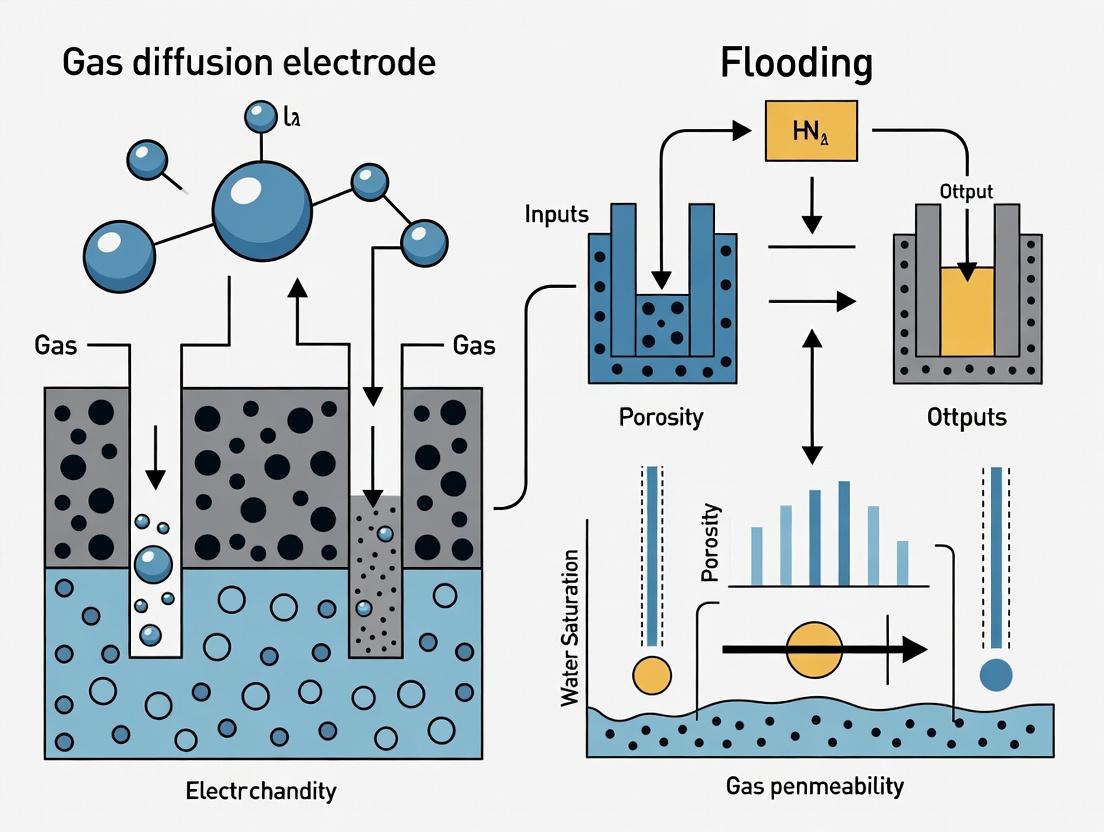
Electrode flooding is a failure mode where the porous structure of a gas diffusion electrode (GDE) becomes inundated with liquid electrolyte, severely impeding the transport of gaseous reactants to the catalytic sites. In biomedical applications—such as implantable biofuel cells, electrochemical biosensors, and neural stimulation/recording devices—this phenomenon is critically detrimental. It leads to rapid performance decay, unstable readings, and device failure, directly impacting the reliability of diagnostic data, the longevity of therapeutic implants, and the accuracy of research findings.
Table 1: Consequences of Electrode Flooding in Key Biomedical Applications
| Application | Primary Consequence of Flooding | Typical Performance Loss | Critical Impact |
|---|---|---|---|
| Implantable Biofuel Cells | O₂ starvation at cathode | >80% drop in power density within hours | Premature failure of pacemaker/neurostimulator power sources |
| Electrochemical Biosensors | Increased diffusion barrier, signal noise | Sensitivity loss of 60-90%, high drift | False negative/positive diagnostic results |
| Neural Interfaces | Increased impedance, charge injection limit degradation | Impedance rise by 200-500% | Reduced signal-to-noise ratio, ineffective stimulation |
| In vitro Cell Electroporation | Inhomogeneous current distribution, heat generation | Cell viability reduction by 40-70% | Irreproducible transfection/therapy outcomes |
Technical Support Center: Troubleshooting & FAQs
Frequently Asked Questions
Q1: During my glucose/O₂ biofuel cell experiment, the open-circuit voltage is stable, but the power output collapses under load. Is this flooding? A: Very likely. A stable OCV indicates the catalyst is initially active, but under load, the demand for O₂ increases. A flooded cathode cannot supply sufficient O₂, causing concentration polarization and a rapid voltage drop. Check by measuring performance at different cathode back-pressures; if performance is insensitive to pressure, flooding is probable.
Q2: My electrochemical biosensor shows significant signal drift in continuous physiological buffer monitoring. Could pore flooding be the cause? A: Yes. Progressive electrolyte intrusion into the electrode's microporous layer changes the active surface area and the effective diffusion distance for analytes, causing baseline drift. This is exacerbated by protein fouling, which synergistically blocks pores.
Q3: How can I quickly diagnose if my experimental GDE is flooded post-test? A: Perform a post-mortem analysis:
- Weight Measurement: Weigh the dry GDE before experiment and after careful drying post-test. A weight gain >5% of the dry weight suggests significant liquid retention.
- Cross-Sectional SEM: Inspect for water accumulation in the diffusion medium and catalyst layer.
- Contact Angle Test: A significant decrease in the water contact angle on the surface indicates loss of hydrophobicity.
Troubleshooting Guide
Problem: Sudden decay in limiting current during dissolved oxygen sensing.
- Check 1: Verify the gas permeability of the diffusion layer. Use the protocol below ("Gas Permeability Test").
- Check 2: Inspect the hydrophobicity of the Microporous Layer (MPL). Reapply or optimize the PTFE binder content.
- Solution: Implement a more robust hydrophobic treatment. See "Experimental Protocol 1" below.
Problem: Unstable reading from an implantable enzyme electrode in vivo.
- Check 1: Confirm the biofouling barrier (e.g., Nafion, polyurethane) is intact and uniformly coated.
- Check 2: Evaluate if the operational voltage range is causing water electrolysis, generating gas bubbles that alter wetting.
- Solution: Incorporate a dual-layer diffusion medium: an inner hydrophobic layer to prevent flooding and an outer hydrophilic biocompatible layer to control tissue integration.
Experimental Protocols for Flooding Mitigation Research
Experimental Protocol 1: Optimizing Hydrophobic Agent Loading in the Microporous Layer (MPL)
Objective: Determine the optimal polytetrafluoroethylene (PTFE) content to prevent electrolyte intrusion while maintaining gas diffusivity.
- Slurry Preparation: Create five batches of MPL slurry containing carbon black (Vulcan XC-72) with PTFE dispersions (e.g., 60 wt%) to achieve final dry PTFE loadings of 10, 20, 30, 40, and 50 wt%.
- Coating: Uniformly coat each slurry onto a carbon paper substrate (e.g., Sigracet 29BC) using a doctor blade.
- Curing: Sinter in a furnace at 340°C for 30 minutes under an inert atmosphere.
- Characterization:
- Contact Angle: Measure static water contact angle.
- Porometry: Determine pore size distribution via capillary flow porometry.
- Performance Test: Assemble in a half-cell and perform a polarization test in a relevant electrolyte (e.g., PBS at 37°C).
Table 2: Typical Results from PTFE Loading Optimization
| PTFE Content (wt%) | Avg. Contact Angle (°) | Mean Pore Size (μm) | Limiting Current Density (mA/cm²) |
|---|---|---|---|
| 10 | 105 | 0.8 | 1.2 |
| 20 | 130 | 0.7 | 2.1 |
| 30 | 145 | 0.6 | 2.5 |
| 40 | 152 | 0.5 | 2.4 |
| 50 | 155 | 0.3 | 1.1 |
Experimental Protocol 2:In-SituElectrochemical Flooding Diagnosis
Objective: Use electrochemical impedance spectroscopy (EIS) to detect flooding in real-time.
- Setup: Configure a standard three-electrode cell with the GDE as the working electrode.
- Operation: Polarize the electrode at its typical operating potential (e.g., 0.4 V vs. Ag/AgCl for an O₂ reduction cathode).
- EIS Measurement: Record a Nyquist plot at regular time intervals (e.g., every 30 minutes) over 8-24 hours. Use a frequency range from 10 kHz to 0.1 Hz.
- Analysis: Monitor the low-frequency impedance (associated with mass transport). A progressive increase in the low-frequency arc diameter is a direct indicator of increasing diffusion resistance due to flooding.
Diagrams & Visualizations
Diagram 1: Flooding-Induced Failure Pathway
Diagram 2: Flooding Diagnosis & Mitigation Workflow
The Scientist's Toolkit: Key Research Reagent Solutions
Table 3: Essential Materials for Flooding Mitigation Research
| Material / Reagent | Function & Role in Flooding Research | Example Product |
|---|---|---|
| Hydrophobic Carbon Substrates | Pre-coated gas diffusion layers (GDLs) with PTFE; baseline for testing. | Sigracet 29BC, AvCarb MGL190 |
| PTFE Dispersion (60 wt%) | Standard hydrophobic agent for creating or modifying microporous layers. | Chemours Teflon PTFE DISP 30 |
| Nafion Perfluorinated Resin | Ionomer/binder; content ratio affects catalyst layer wettability. | Sigma-Aldrich 527084 |
| Silicone Rubber Sealants | For creating stable, leak-free electrochemical cell gasketing. | Dow DOWSIL 734 |
| Simulated Physiological Electrolyte | For testing under biologically relevant conditions (pH, ions, temperature). | Phosphate Buffered Saline (PBS), pH 7.4 @ 37°C |
| Capillary Flow Porometer | Instrument to characterize the pore size distribution of GDLs. | PMI Capillary Flow Porometer |
| Contact Angle Goniometer | Measures surface wettability to quantify hydrophobicity. | Ramé-Hart Model 250 |
| Microporous Hydrophobic Membranes | Used as protective, gas-permeable barriers in biosensors. | Gore-Tex ePTFE Membrane |
Troubleshooting Guides & FAQs
Q1: My PEM fuel cell exhibits sudden voltage drops under high current density. I suspect cathode flooding. How can I diagnose and address this?
A: This is a classic symptom of liquid water accumulation in the cathode GDL, blocking oxygen transport. Follow this diagnostic protocol:
Diagnosis:
- Perform Electrochemical Impedance Spectroscopy (EIS) at the operating current. A significant increase in the low-frequency arc (associated with mass transport resistance) confirms flooding.
- Measure pressure drop across the cathode flow field. A gradual increase supports liquid water accumulation.
- Ex-situ: Characterize used GDLs with SEM/contact angle goniometry to observe pore blockage and hydrophobicity loss.
Primary Solutions:
- Increase GDL hydrophobicity: Implement in-situ MPL coating repair or use GDLs with higher PTFE loading (20-30% wt. in macroporous substrate).
- Optimize gas flow: Increase cathode stoichiometry or use pulsed/purge cycles to enhance water removal.
- Thermal management: Slightly increase cell temperature (e.g., from 65°C to 70°C) to enhance vapor-phase transport.
Q2: I observe catalyst layer (CL) cracking or detachment from the MPL after hot-pressing. What are the causes and remedies?
A: This is often due to mismatched mechanical and thermal properties.
Causes:
- Excessive hot-pressing temperature or pressure.
- Significant difference in the coefficient of thermal expansion (CTE) between the CL and the MPL.
- Poor adhesion due to incompatible surface energies.
Remedies:
- Optimize hot-pressing protocol: Reduce temperature (e.g., 130°C vs. 150°C) and pressure (e.g., 0.5 MPa vs. 1.0 MPa), as shown in Table 2.
- Introduce an interfacial layer: Apply a dilute Nafion or PTFE solution on the MPL surface prior to CL decaling to improve adhesion.
- Use a more flexible CL ionomer or incorporate reinforcing agents (e.g., nanofibers).
Q3: How do I differentiate between performance loss from MPL pore flooding versus macroporous substrate flooding?
A: Targeted characterization is key. Use the following experimental protocol:
Ex-situ Water Injection Test:
- Use a custom setup to inject water into the substrate side of a GDL sample placed on a porous plate.
- Measure capillary pressure vs. saturation. MPL flooding is indicated by a sharp pressure rise at low saturation (<20%), while substrate flooding occurs at higher saturation and lower pressure.
In-situ Segmented Cell Analysis:
- Use a cell with segments along the flow field.
- Under flooding conditions, localized current density in segments near the outlet will drop more severely if the macroporous substrate is flooded, while a more uniform drop suggests MPL/catalyst layer flooding.
Pore Network Modeling: Simulate water percolation using the structural parameters from Table 1. Match simulation results to your polarization curve to identify the flooded region.
Key Experimental Protocols
Protocol 1: Determining the Effective Porosity & Mean Pore Size of GDL Components
Objective: Quantify the porous structure of the macroporous substrate and MPL separately. Materials: Mercury Intrusion Porosimetry (MIP) analyzer, sample of bare substrate, sample of substrate+MPL. Method:
- Cut 1 cm² samples. Dry in a vacuum oven at 80°C for 4 hours.
- For the bare substrate, place the sample in the MIP penetrometer. Apply low pressure (0.1 to 30 psia) to analyze macropores (0.1-30 μm).
- For the substrate+MPL sample, the MIP will measure the entire pore spectrum. The high-pressure stage (up to 60,000 psia) characterizes the MPL's micropores (0.01-0.1 μm).
- The pore size distribution of the MPL is obtained by subtracting the substrate's contribution from the composite sample data, or by directly testing a freestanding MPL if possible. Data Analysis: Use the Washburn equation. Report median pore diameter (μm) and total intrusion volume (mL/g) for each region.
Protocol 2: In-situ Measurement of Water Distribution in the GDL
Objective: Visualize and quantify liquid water saturation in the GDL during operation. Materials: Transparent fuel cell with a conductive window, high-speed camera, microscope lens, LED backlight. Method:
- Assemble a single cell with a transparent endplate (e.g., polycarbonate with a gold-coated current collector) on the cathode side.
- Operate the cell at a constant current density (e.g., 1.0 A/cm²).
- Use the high-speed camera with backlight illumination to capture images through the GDL thickness (edge-on) or plane (through-the-window).
- Apply image processing (thresholding based on grayscale intensity) to distinguish liquid water (dark pixels) from gas pores (bright pixels). Data Analysis: Calculate water saturation ( Sw = \frac{A{water}}{A{pores}} ), where ( A ) is the area of pixels. Plot ( Sw ) vs. time or current density.
Table 1: Typical Structural Properties of GDL Components
| Component | Thickness (μm) | Mean Pore Diameter (μm) | Porosity (%) | Typical PTFE Content (wt.%) | Primary Function |
|---|---|---|---|---|---|
| Macroporous Substrate (Carbon Paper) | 180 - 230 | 20 - 50 | 70 - 80 | 5 - 20 (Hydrophobic treatment) | Bulk gas transport, mechanical support, heat conduction, water removal. |
| Microporous Layer (MPL) | 20 - 50 | 0.1 - 0.5 | 40 - 60 | 20 - 40 | Interface regulation, reduces CL intrusion, manages capillary pressure, enhances back-diffusion. |
| Catalyst Layer (CL) | 5 - 20 | 0.01 - 0.1 (Ionomer) | 30 - 50 | N/A (contains ionomer) | Site of electrochemical reactions (HOR/ORR), electron/proton conduction. |
Table 2: Impact of Hot-Pressing Conditions on GDL/CL Interface Resistance & Performance
| Hot-Press Temp. (°C) | Hot-Press Pressure (MPa) | Contact Resistance (mΩ·cm²) | Peak Power Density (mW/cm²) | Observed Interface Morphology |
|---|---|---|---|---|
| 130 | 0.5 | 8.2 | 980 | Good adhesion, no cracking. |
| 130 | 1.0 | 7.5 | 950 | Slight CL compression, minor cracks. |
| 150 | 0.5 | 7.8 | 920 | Some ionomer flow into MPL. |
| 150 | 1.0 | 7.1 | 860 | Severe CL cracking & delamination. |
Diagrams
Title: Water & Gas Transport Pathways in the GDL Trio
Title: Diagnostic Logic for Fuel Cell Flooding Issues
The Scientist's Toolkit: Research Reagent Solutions
| Item | Function in GDL/Flooding Research | Typical Specification/Example |
|---|---|---|
| Carbon Paper/Felt Substrate | The macroporous backbone of the GDL. Provides structure and primary gas diffusion paths. | SIGRACET GDL series (SGL Carbon), TGP-H series (Toray). Thickness: 190-230 µm. |
| PTFE Dispersion | Hydrophobic agent. Coated onto the substrate/MPL to create water-repellent pores and prevent flooding. | 60 wt.% dispersion in water (e.g., Sigma-Aldrich). Often diluted to 20-30% for impregnation. |
| MPL Carbon Powder | Fine carbon particles to form the microporous layer. Creates a fine-pore structure for capillary management. | Vulcan XC-72R, Acetylene Black, Ketjenblack EC-300J. Primary particle size: 30-50 nm. |
| Ionomer Solution | Binder for the MPL (optional) and essential component of the Catalyst Layer. Facilitates proton conduction. | 5-20 wt.% Nafion perfluorinated resin solution (e.g., D521 from FuelCellStore). |
| Contact Angle Goniometer | Measures wettability/hydrophobicity of GDL surfaces before/after testing. Critical for flooding analysis. | Measures static and dynamic contact angles. |
| Mercury Porosimeter | Characterizes the pore size distribution and porosity of the GDL substrate and MPL. | Capable of pressures from 0.1 to 60,000 psia to measure pores from 0.003 to 360 µm. |
| Ex-situ Water Injection Setup | Custom apparatus to simulate capillary pressure-saturation behavior of GDL materials. | Includes syringe pump, pressure sensor, camera, and sample chamber. |
Technical Support Center: Troubleshooting GDE Flooding in Research Experiments
This support center provides targeted guidance for researchers investigating flooding phenomena in Gas Diffusion Electrodes (GDEs), framed within the thesis context of advancing stable fuel cell and electrolyzer performance.
Troubleshooting Guides & FAQs
Q1: During cyclic polarization testing, my GDE performance degrades rapidly, with a significant voltage drop at high current densities. What is the primary culprit and how can I confirm it? A1: This is a classic symptom of electrode flooding, most often driven by excessive capillary pressure overcoming the hydrophobic barriers in the microporous layer (MPL). To confirm:
- Perform Electrochemical Impedance Spectroscopy (EIS): A significant increase in the low-frequency arc (mass transport impedance) is indicative of liquid water accumulation.
- Measure Pressure Drop: In an operating flow cell, an unexpected increase in pressure drop across the gas channel can signal water blockage.
- Post-mortem Analysis: Use Cryogenic Scanning Electron Microscopy (Cryo-SEM) on a stopped experiment to visualize water distribution and pore structure without altering the liquid phase.
Q2: My PTFE-bound GDEs show a gradual loss of hydrophobicity over time. How can I test for this and what materials are more stable? A2: Hydrophobicity loss is often due to chemical attack on the binder (e.g., PTFE) or physical detachment. Testing and solutions include:
- Ex-Situ Test: Measure the static contact angle of a water droplet on the GDE surface using a goniometer over accelerated aging cycles (e.g., immersion in hot electrolyte).
- In-Situ Indicator: A steady increase in limiting current for oxygen reduction (ORR) in a half-cell, under specific humidities, can indicate improved water wetting due to hydrophobicity loss.
- Alternative Materials: Consider fluorinated ethylene propylene (FEP) or integrated hydrophobic agents like graphene treated with fluoropolymers, which may offer higher chemical stability.
Q3: After long-term testing, my GDE's pore volume and porosity decrease. How do I diagnose pore collapse and prevent it? A3: Pore structure collapse is often a mechanical compression issue exacerbated by liquid water.
- Diagnosis: Compare BET surface area and pore volume distributions from nitrogen physisorption data of fresh vs. aged samples. A shift in the pore size distribution curve towards smaller diameters is a key indicator.
- Prevention Protocol:
- Incorporate mechanically robust carbon supports (e.g., graphitized carbon blacks, carbon nanotubes).
- Optimize the binder-to-carbon ratio in the MPL to provide resilience without blocking pores.
- Implement potential cycling protocols that avoid extreme cathodic potentials which can exacerbate carbon corrosion and structural weakening.
Table 1: Common Hydrophobic Agents & Their Properties
| Agent | Typical Loading (wt%) | Key Advantage | Operational Limitation | Contact Angle (Fresh) |
|---|---|---|---|---|
| Polytetrafluoroethylene (PTFE) | 5-30% | High hydrophobicity, widely used | Potential degradation at high potentials | 130° - 150° |
| Fluorinated Ethylene Propylene (FEP) | 10-40% | Better thermal/chemical stability than PTFE | Higher processing temperature required | 125° - 140° |
| Polyvinylidene Fluoride (PVDF) | 5-20% | Good adhesion and processability | Lower hydrophobicity than PTFE | 90° - 120° |
Table 2: Characterization Techniques for Flooding Diagnosis
| Technique | Measures | Indicator of Flooding/Collapse | Sample Requirement |
|---|---|---|---|
| Mercury Intrusion Porosimetry (MIP) | Pore size distribution, total pore volume | Reduction in pore volume, shift to smaller pore sizes | Dry sample (~100 mg). Destructive. |
| Cryogenic SEM | Visual water distribution, pore morphology | Liquid water in pores, deformed structure | Frozen, hydrated sample. |
| Electrochemical Impedance Spectroscopy (EIS) | Charge transfer & mass transport resistances | Large increase in low-frequency impedance | Operating cell or half-cell. |
| Contact Angle Goniometry | Surface wettability | Decrease in advancing/receding contact angle | Small sample section (~1 cm²). |
Experimental Protocols
Protocol 1: Accelerated Hydrophobicity Loss Test via Ex-Situ Aging
- Sample Preparation: Cut GDE samples into 2x2 cm squares.
- Aging Bath: Immerse samples in a 1.0 M H₂SO₄ (or relevant electrolyte) solution maintained at 60°C.
- Cycling: Periodically remove a sample (e.g., at 24h, 48h, 96h), rinse thoroughly with deionized water, and dry at 80°C for 1 hour in an oven.
- Measurement: Measure the static contact angle using a goniometer with a 5 µL water droplet at ambient conditions. Average over 5 different spots on the sample.
- Analysis: Plot contact angle vs. aging time to quantify the rate of hydrophobicity loss.
Protocol 2: In-Situ Flooding Detection via Limiting Current
- Setup: Use a standard 3-electrode electrochemical half-cell with the GDE as the working electrode, placed in a holder exposing a defined geometric area (e.g., 0.5 cm²).
- Environment: Saturate the electrolyte (e.g., 0.1 M HClO₄) with pure O₂ for 30 minutes. Maintain O₂ bubbling throughout.
- Polarization: Perform a linear sweep voltammetry (LSV) scan from 1.0 V to 0.2 V vs. RHE at a slow scan rate (e.g., 1 mV/s).
- Observation: Identify the limiting current plateau. An increase in this plateau value over identical tests indicates improved oxygen access, often from increased wettability (hydrophobicity loss).
Visualizations
Title: Interlinked Mechanisms Leading to GDE Flooding
Title: Stepwise Experimental Diagnosis for GDE Failure
The Scientist's Toolkit: Research Reagent Solutions
Table 3: Essential Materials for GDE Flooding Resistance Studies
| Item | Function & Rationale | Example/ Specification |
|---|---|---|
| High-Structure Carbon Black | Provides conductive, porous scaffold for catalyst and MPL. High surface area and pore volume resist collapse. | Vulcan XC-72R, Ketjenblack EC-300J, Shawinigan Acetylene Black |
| Fluoropolymer Binder | Imparts hydrophobicity, binds carbon particles, and creates a three-phase boundary. Critical for managing water. | PTFE dispersion (60 wt%), FEP dispersion, PVDF pellets |
| Microporous Layer (MPL) Carbon | Specifically engineered carbon with defined particle size and porosity to tailor capillary pressure. | Graphitized carbon powder, Carbon Nanotube (CNT) powder |
| Polyol Solvent (for Ink) | Disperse catalyst/binder uniformly for coating. Influences layer morphology and porosity. | Isopropanol, Ethylene Glycol, Nafion/water/alcohol mixtures |
| Gas Diffusion Layer (GDL) Substrate | Macro-porous carbon fiber paper or cloth. Provides mechanical support and gas/liquid distribution. | Sigracet (SGL), AvCarb, Toray Paper (TGP-H series) |
| Accelerated Stress Test (AST) Electrolyte | Simulates harsh fuel cell conditions to study degradation mechanisms like carbon corrosion. | 0.1-1.0 M H₂SO₄ or HClO₄, 0.1 M KOH (for AEMFC) |
| Reference Electrode | Enables accurate potential control in half-cell experiments to isolate GDE phenomena. | Reversible Hydrogen Electrode (RHE), Hg/Hg₂SO₄ |
Technical Support Center
Troubleshooting Guides
Issue 1: Insufficient Water Management Leading to Electrode Flooding
- Problem: Voltage instability and rapid performance decay during H₂/O₂ operation.
- Root Cause: Inadequate hydrophobic gradient or low PTFE/Carbon black content, failing to expel excess liquid water.
- Solution Steps:
- Verify the PTFE to carbon ratio. For a standard microporous layer (MPL), aim for 20-40 wt% PTFE.
- Check the drying/curing protocol. Sinter PTFE at 340-350°C for 15-30 minutes to ensure proper fibril formation.
- Characterize pore size distribution. Use mercury intrusion porosimetry (MIP) to confirm a bimodal distribution with peaks in the 30-50 nm (hydrophobic pores) and 100-300 nm (transport pores) ranges.
- Validation Test: Perform limiting current density measurement under fully humidified conditions. A well-tuned electrode will maintain a stable plateau.
Issue 2: Delamination of the Microporous Layer (MPL) from the Gas Diffusion Layer (GDL) Substrate
- Problem: MPL flakes off during handling or cell assembly, causing increased contact resistance and erratic flooding.
- Root Cause: Poor binder integrity or incorrect application pressure/temperature.
- Solution Steps:
- Review hydrophobic binder (e.g., fluorinated ethylene propylene - FEP) content. Typically, 5-10 wt% in the MPL slurry enhances adhesion.
- Ensure the GDL substrate (carbon paper/felt) is properly pre-treated (e.g., via plasma or mild oxidation) to increase surface energy for better slurry adhesion.
- Optimize the hot-pressing procedure: 130-150°C, 1-2 MPa for 2-5 minutes.
Issue 3: Excessive Hydrophobicity Causing Membrane Dry-Out
- Problem: High-frequency resistance (HFR) increases under low humidity inlet gases, indicating membrane dehydration.
- Root Cause: Overly hydrophobic MPL or catalyst layer, blocking back-diffusion of water from the cathode.
- Solution Steps:
- Titrate PTFE/FEP content downward in 5 wt% increments.
- Introduce a secondary, more hydrophilic carbon (e.g., acetylene black) to create a balanced wetting profile.
- Implement a gradient design in the MPL, with lower hydrophobicity near the catalyst layer.
Frequently Asked Questions (FAQs)
Q1: What is the optimal PTFE content for flood prevention in a carbon-based GDL? A: The optimal range is highly dependent on operating conditions. For standard PEMFC operation at 60-80°C and 100% RH, 20-30 wt% PTFE in the MPL is a robust starting point. For higher temperature or liquid water exposure, content up to 40 wt% may be necessary. Refer to Table 1 for performance data.
Q2: Can I use alternative hydrophobic agents instead of PTFE? A: Yes. Fluorinated ethylene propylene (FEP) and polyvinylidene fluoride (PVDF) are common alternatives. FEP offers a lower processing temperature (~275°C) and can act as both hydrophobe and binder. PVDF provides different mechanical properties but may have lower chemical stability in fuel cell environments.
Q3: How does the carbon particle type affect flooding behavior? A: Critically. Carbon black (e.g., Vulcan XC-72) with high surface area creates finer pores, enhancing capillary pressure for water expulsion. Graphitized carbon or carbon nanotubes improve electronic conductivity and corrosion resistance but may alter the pore structure. A blend is often used.
Q4: What is the standard protocol for measuring pore size distribution? A: Mercury Intrusion Porosimetry (MIP) is the standard. The protocol involves: 1. Cutting a clean sample (∼1 cm²) from the GDL. 2. Drying in a vacuum oven at 80°C for 4 hours. 3. Loading into a penetrometer and evacuating to low pressure (<50 µmHg). 4. Intruding mercury at pressures from 0.1 to 60,000 psi, logging volume intruded vs. pressure. 5. Using the Washburn equation to convert pressure to pore diameter.
Q5: How can I quickly test the hydrophobic quality of my fabricated GDL? A: Perform a simple water droplet contact angle measurement. Place a 5µL water droplet on the GDL surface and image with a goniometer. A static contact angle >130° typically indicates sufficient surface hydrophobicity. For dynamic assessment, measure the advancing/receding angles.
Data Presentation
Table 1: Performance Comparison of GDLs with Varying PTFE Content
| PTFE Content (wt% in MPL) | Peak Power Density (mW/cm²) @ 80°C, 100% RH | Limiting Current Density (A/cm²) | HFR @ 1A/cm² (Ω·cm²) | Contact Angle (°) |
|---|---|---|---|---|
| 15 | 850 | 1.2 | 0.12 | 125 |
| 25 | 1100 | 1.8 | 0.10 | 142 |
| 35 | 1050 | 1.7 | 0.15 | 151 |
| 45 | 720 | 1.1 | 0.18 | 155 |
Data synthesized from recent literature (2023-2024). Conditions: H₂/Air, 150 kPaabs.
Table 2: Key Properties of Common Hydrophobic Binders
| Binder | Processing Temperature | Key Function | Advantage | Disadvantage |
|---|---|---|---|---|
| PTFE | 340-350°C (Sintering) | Hydrophobe, forms fibrils | Excellent hydrophobicity, stable | High temp., pure binder function |
| FEP | ~275°C (Melting) | Hydrophobe & Binder | Lower temp., good adhesion | Slightly lower stability than PTFE |
| PVDF | ~175°C (Dissolves) | Hydrophobe & Binder | Soluble, easy processing | Potential degradation in fuel cell |
Experimental Protocols
Protocol: Fabrication of a Dual-Layer Hydrophobic MPL Objective: Create a GDL with a gradient hydrophobic MPL to prevent flooding while maintaining hydration. Materials: Carbon paper substrate, Carbon Black (Vulcan XC-72R), PTFE dispersion (60 wt%), FEP dispersion, Isopropyl Alcohol (IPA), Deionized Water. Procedure:
- Slurry A (High PTFE, 35 wt%): Mix 2.0g carbon black with 15ml IPA and 15ml DI water. Sonicate for 20 min. Add 2.33g of PTFE dispersion. Stir for 60 min.
- Slurry B (Low PTFE, 20 wt%): Mix 2.0g carbon black with 15ml IPA/15ml DI water. Sonicate. Add 1.0g of PTFE dispersion and 0.5g FEP dispersion. Stir.
- Coating: Apply Slurry A (high PTFE) directly to the carbon paper substrate via doctor blade. Dry at 80°C for 30 min.
- Coating: Apply Slurry B (low PTFE) on top of the first layer. Dry at 80°C for 30 min.
- Curing: Sinter the coated GDL in a muffle furnace at 340°C for 25 minutes (ramp rate 5°C/min).
- Characterization: Measure pore size (MIP), contact angle, and in-situ fuel cell performance.
Visualization
Diagram: Hydrophobic Pore Network Prevents Electrode Flooding
Diagram: Workflow for Fabricating Hydrophobic Gas Diffusion Layer
The Scientist's Toolkit
Research Reagent Solutions for GDL Hydrophobicity Studies
| Item | Function | Example/Notes |
|---|---|---|
| Carbon Black (Vulcan XC-72R) | Conductive backbone for MPL; defines primary pore structure. | High surface area (~250 m²/g) for fine pore creation. |
| PTFE Dispersion (60% wt in water) | Standard hydrophobic agent; forms a fibrous network upon sintering. | Dilute to ~20% with DI water/Isopropanol for slurry making. |
| FEP Dispersion | Hydrophobic binder; enhances MPL adhesion to substrate. | Lower processing temperature than PTFE. |
| Carbon Paper Substrate (e.g., Toray TGP-H-060) | Macroporous, conductive backing layer. | Often pre-treated with a 5-10% PTFE for baseline hydrophobicity. |
| Isopropyl Alcohol (IPA) | Solvent for slurry preparation; improves wetting of carbon. | Typically used in 1:1 mix with DI water. |
| Mercury Intrusion Porosimeter | Equipment for measuring pore size distribution & volume. | Critical for quantifying hydrophobic pore network. |
| Contact Angle Goniometer | Equipment for measuring surface wettability. | Quick QC check for hydrophobic treatment success. |
Technical Support Center
Troubleshooting Guides & FAQs
Section 1: Pressure Gradient Management
Q1: My electrode floods immediately upon applying a cathodic potential, even with moderate gas pressure. What is the likely cause?
- A: This indicates a failure in the hydrophobic barrier. Likely causes are: 1) Insufficient or degraded Polytetrafluoroethylene (PTFE) binder in the microporous layer (MPL), 2) Excessive compression of the gas diffusion layer (GDL) during cell assembly, collapsing pore structures, or 3) An MPL crack formation creating a direct hydrophilic path. First, verify assembly torque. Then, characterize the GDL's ex-situ hydrophobicity via contact angle measurement. Re-cast the MPL if necessary.
Q2: How do I determine the optimal differential pressure (ΔP) between the gas and electrolyte channels to prevent flooding?
- A: The optimal ΔP is system-specific. Follow this protocol:
- Start with equal pressures (ΔP=0) at your standard operating temperature.
- Gradually increase the gas channel pressure in +0.5 kPa increments while monitoring voltage stability at a fixed current density.
- The point just before a sharp, sustained voltage drop indicates flooding. The stable point 0.2-0.5 kPa below this is your maximum allowable gas-side pressure. A slight positive electrolyte pressure (0.1-0.3 kPa) is often beneficial.
- Document this critical ΔP for your specific GDL and electrolyte.
- A: The optimal ΔP is system-specific. Follow this protocol:
Section 2: Temperature Fluctuation Control
Q3: Cyclic voltage drops are observed during long-term experiments, correlating with heater cycling. Is this flooding?
- A: Yes, this is likely temperature-induced cyclic flooding. A drop in local temperature increases the relative humidity, causing vapor condensation in pores. Conversely, a temperature spike can evaporate electrolyte, leading salt precipitation and clogging upon re-cooling. Ensure temperature stability of both gas feed and cell body to ±0.5°C. Consider pre-saturating the gas at the cell operating temperature using a humidifier with precise temperature control.
Q4: What is the best practice to isolate thermal effects from electrochemical effects during testing?
- A: Implement a phased experimental protocol:
- Phase I (Thermal Only): Operate the cell at open-circuit potential (OCP) while cycling temperature. Monitor pressure and flow rates. Any liquid water accumulation is purely thermally driven.
- Phase II (Electrochemical + Thermal): Apply a current density. The difference in flooding behavior between Phase II and I quantifies the electrochemically driven water production's contribution.
- A: Implement a phased experimental protocol:
Section 3: Electrolyte Management
Q5: Electrolyte composition seems to shift over time, with pH drift. How can I manage this?
- A: pH drift indicates insufficient buffering capacity or crossover/reaction of CO2 from air. For alkaline electrolytes, carbonate formation is inevitable. Implement a recirculation system with an in-line pH probe and a small reservoir. For precise control, use an automated titration system adding dilute acid/base to maintain pH. For acidic systems, use phosphate or other appropriate buffers at concentrations >0.1 M.
Q6: How can I differentiate between flooding due to pressure/temperature and flooding due to electrolyte surfactant contamination?
- A: Perform a Capillary Flow Porometry test on a fresh and a used GDL sample. Contamination by surfactants will permanently alter the pore wetting properties, shifting the bubble point pressure and mean flow pore diameter. If ex-situ porometry shows changes, the GDL's hydrophobicity is compromised. If not, the flooding is operational (pressure/temperature) and likely reversible by drying.
Table 1: Critical Pressure Gradients for Common GDLs (in 1M KOH)
| GDL Type | Thickness (µm) | PTFE Loading (wt%) | Stable ΔP Range (Gas side positive) (kPa) | Flooding ΔP (kPa) |
|---|---|---|---|---|
| Sigracet 39BB | 235 | 5 | 0.5 - 1.2 | 1.5 |
| Freudenberg H23 | 210 | 5 | 0.3 - 0.9 | 1.2 |
| AvCarb MGL190 | 190 | 0 (w/ MPL) | 1.0 - 2.0 | 2.3 |
Table 2: Impact of Temperature Stability on Voltage Decay Rate
| Electrolyte | Temp Setpoint (°C) | Temp Fluctuation (±°C) | Voltage Decay Rate (mV/hr) | Primary Cause |
|---|---|---|---|---|
| 0.1 M HClO4 | 25 | 0.2 | 0.3 | Normal catalyst aging |
| 0.1 M HClO4 | 25 | 1.5 | 2.1 | Cyclic pore condensation |
| 1 M KOH | 40 | 0.5 | 0.8 | Carbonate formation |
| 1 M KOH | 40 | 2.0 | 4.5 | Carbonate formation + flooding |
Experimental Protocols
Protocol 1: Determination of Critical Flooding Pressure Gradient
- Setup: Assemble electrochemical cell with reference electrode. Connect precise digital pressure regulators & sensors to gas and electrolyte lines.
- Conditioning: Activate catalyst layer via cyclic voltammetry. Flow inert gas (N2) and electrolyte at equal pressure for 1 hour.
- Testing: Apply target current density. Set electrolyte channel pressure (P_elec) to a constant 101.0 kPa.
- Ramp: Increase gas channel pressure (P_gas) from 101.0 kPa in steps of 0.1 kPa every 2 minutes.
- Monitor: Record cell voltage and high-frequency resistance.
- Endpoint: The test concludes when voltage drops by >50 mV from its stable maximum. The ΔP (Pgas - Pelec) at the previous step is the Critical Flooding Pressure Gradient.
Protocol 2: Electrolyte Buffering Capacity Verification
- Titration Solution: Prepare 0.1M HCl (for alkaline electrolytes) or 0.1M NaOH (for acidic electrolytes).
- Baseline: Measure initial pH of 100 mL of your fresh electrolyte.
- Stressing: Sparge CO2 gas (for alkaline) or O2 gas (for acidic) through the electrolyte at 50 sccm for 30 minutes.
- Titration: Under continuous stirring, add the titration solution in 0.1 mL increments. Record pH after each addition.
- Analysis: Plot pH vs. volume of titrant. The flattest region of the curve indicates the buffering zone. Ensure your operational pH is within this zone.
Diagrams
Diagram 1: Flooding Trigger Analysis Pathway
Diagram 2: GDL Operational Stress Workflow
The Scientist's Toolkit: Research Reagent Solutions
Table 3: Essential Materials for Flooding Mitigation Experiments
| Item | Function | Key Consideration |
|---|---|---|
| Digital Pressure Regulator | Precisely controls and logs gas/electrolyte channel pressure to maintain sub-critical ΔP. | Resolution <0.05 kPa, response time <1s. |
| PTFE-coated GDL (e.g., Sigracet 39BB) | Provides hydrophobic macroporous substrate for gas diffusion and liquid blocking. | PTFE loading (5-20%), thickness, and MPL presence must be documented. |
| Immersion Circulator | Maintains precise temperature of cell and reactant gases to prevent condensation. | Stability ≤±0.1°C, compatible with your electrolyte chemistry. |
| Buffer Salts (e.g., K2HPO4/KH2PO4) | Maintains electrolyte pH within a stable range, preventing precipitation or property shifts. | Choose pKa within ±1 of target pH. Ensure electrochemical inertness. |
| In-line Gas Humidifier | Saturates inlet gas at cell temperature, preventing drying or extra condensation in the GDL. | Temperature must be controlled independently of the cell. |
| Contact Angle Goniometer | Quantifies the hydrophobicity of GDL samples before/after testing to assess degradation. | Measure both advancing and receding angles. |
| Capillary Flow Porometer | Characterizes the pore size distribution and bubble point pressure of GDLs. | Critical for diagnosing permanent wettability changes. |
Building Resilient Electrodes: Advanced Fabrication and Operational Strategies for Flood Mitigation
Welcome to the Gas Diffusion Electrode (GDE) Hydrophobicity Tuning Technical Support Center
This center supports researchers focused on mitigating electrode flooding through precise material engineering, a critical aspect of advancing fuel cell and CO2 reduction reactor durability.
Troubleshooting Guides & FAQs
Q1: During ink preparation, my PTFE/PVDF dispersion agglomerates or gels. What causes this and how can I prevent it? A: This is often due to solvent incompatibility or excessive shear. PTFE is especially sensitive.
- Cause & Solution Table:
Cause Diagnostic Check Corrective Action Solvent Polarity Mismatch PTFE in high-polarity solvent (e.g., water, high [alcohol]). Use a recommended solvent system: e.g., 1:1 water/isopropanol for PTFE; N-Methyl-2-pyrrolidone (NMP) for PVDF. Excessive Sonication Energy/Time Localized heating > 60°C observed. Use pulsed sonication (5s on, 10s off) in an ice bath. Total time < 15 mins. Incompatible Dispersant Dispersion fails without other additives. Use a nonionic surfactant (e.g., Triton X-100, ~0.1 wt%) or adjust pH for electrostatic stabilization.
Q2: My coated GDE shows non-uniform wetting (patchy hydrophobicity). How do I achieve a consistent coating? A: Uniformity is key for consistent triple-phase boundaries.
- Protocol for Blade-Coating a Uniform Hydrophobic Layer:
- Substrate Prep: Clean the gas diffusion layer (GDL) with isopropanol in an ultrasonic bath for 5 min. Dry at 80°C for 30 min.
- Ink Formulation: Prepare a well-dispersed ink. Example: 3 wt% PTFE, 0.1 wt% Triton X-100 in 50/50 water/IPA. Ball mill for 2 hrs.
- Coating: Use a doctor blade. Set gap to 150-250 µm. Maintain a constant speed of 5 mm/s.
- Drying: Dry at room temperature for 1 hr, then 80°C for 1 hr in air.
- Curing/Sintering: Critical Step. For PTFE: Heat at 340°C for 30 min (under N2 if carbon substrate). For PVDF: Heat at 160°C for 1 hr.
Q3: How do I quantitatively evaluate and compare the hydrophobicity of my PTFE vs. PVDF vs. novel fluoropolymer coatings? A: Use static/dynamic contact angle (CA) and electrochemical flooding tests.
- Quantitative Measurement Table:
Method Protocol Summary Key Metric & Interpretation Static Contact Angle Sessile drop (5 µL DI water). Measure via goniometer. CA > 90°: Hydrophobic. PTFE: ~110-130°. PVDF: ~90-100°. Higher CA indicates greater hydrophobicity. Electrochemical Flooding Test Run GDE in single-cell at constant current (~200 mA/cm²). Monitor voltage. Voltage Drop Rate: A slower voltage decay over time indicates better water management and anti-flooding performance. Capillary Flow Porometry Measure pressure required to push wetting liquid through pores. Mean Pore Size & Distribution: Shift to larger pore size post-coating indicates hydrophobic pore lining, beneficial for gas transport.
Q4: My novel fluorinated polymer coating improves hydrophobicity but drastically increases electrode resistance. What's the trade-off? A: You are encountering the classic hydrophobicity-conductivity trade-off. Excessive or thick polymer films insulate carbon particles.
- Solution Protocol: Optimization of Loading:
- Prepare a series of inks with polymer loadings from 1-10 wt% (relative to carbon).
- Coat identical GDEs using the protocol from Q2.
- Characterize each: Measure sheet resistance (4-point probe) and water contact angle.
- Plot CA vs. Resistance. The optimal point is the knee of the curve where CA increase plateaus but resistance rise accelerates. This is typically 2-5 wt% for PTFE/PVDF.
The Scientist's Toolkit: Research Reagent Solutions
| Reagent/Material | Function in Hydrophobicity Tuning | Key Consideration |
|---|---|---|
| PTFE Dispersion (60 wt% in water) | The gold-standard hydrophobic binder. Forms fibrils upon sintering, creating a porous, water-repellent network. | Sintering temperature (≈340°C) is critical. Can be mechanically unstable. |
| PVDF Powder/Pellets | A soluble alternative. Provides adhesion and hydrophobicity, processed at lower temperatures. | Requires strong solvents (e.g., NMP). Lower intrinsic hydrophobicity than PTFE. |
| Perfluoropolyether (PFPE)-based Coatings | Novel low-surface-energy polymer. Can be grafted or coated as a thin film for extreme hydrophobicity. | Expensive. Must verify electrochemical inertness in your system. |
| Gas Diffusion Layer (GDL e.g., Sigracet 39BB) | The macroporous carbon fiber substrate. Provides mechanical support and gas/liquid transport. | Pre-treatment (e.g., with a hydrophobic coating) is often necessary. |
| N-Methyl-2-pyrrolidone (NMP) | Polar aprotic solvent. Ideal for dissolving PVDF and other fluoropolymers without agglomeration. | High boiling point requires careful drying. Handle with appropriate PPE. |
| Isopropyl Alcohol (IPA)/Water Mixture | Common dispersing medium for PTFE and carbon. Adjust ratio to control evaporation rate and dispersion stability. | Flammable. Standard lab safety required. |
Experimental Workflow & Logical Framework
Diagram Title: Workflow for GDE Hydrophobicity Optimization
Diagram Title: Hydrophobicity-Conductivity Trade-off Logic
Technical Support Center: Troubleshooting GDL Experiments
This technical support center provides guidance for common experimental challenges encountered during research on optimizing Gas Diffusion Layer (GDL) pore structures to address flooding in PEM fuel cells and related electrochemical devices.
Frequently Asked Questions (FAQs) & Troubleshooting
Q1: During water injection porosimetry (MIP) testing, my GDL sample shows a significant hysteresis between intrusion and extrusion curves. What does this indicate and how does it affect my pore size distribution analysis?
A: Significant hysteresis often indicates "ink-bottle" pores—larger cavities accessible only through smaller throats. During intrusion, high pressure is needed to push mercury through the small throat, but during extrusion, the mercury remains trapped in the larger cavity until very low pressure. This can lead to an underestimation of larger pore volumes in your distribution. To mitigate:
- Combine with other techniques: Use data from nitrogen adsorption (for micropores/mesopores) or capillary flow porometry (for through-pore throat sizes) to create a composite model.
- Apply advanced interpretation models: Use software that applies network models to correct for pore trapping effects rather than relying solely on the Washburn equation.
Q2: My fabricated gradient porosity GDL performs worse in single-cell testing than a homogeneous one, with higher mass transport losses at high current density. What could be the cause?
A: This failure mode suggests the gradient is opposing effective water management. Common culprits:
- Incorrect gradient direction: For a cathode GDL, a porosity gradient that increases from the catalyst layer (CL) to the flow field may be flooding the CL interface. The typical design for flooding mitigation is a decreasing porosity gradient (finer pores at the CL, larger pores at the flow field) to passively drive liquid water away from the reaction site.
- Abrupt transition zone: A sharp boundary between layers can create a capillary pressure barrier, trapping water. Ensure a gradual, continuous gradient in pore size.
- Excessive hydrophobicity gradient: If your treatment (e.g., PTFE) gradient is too steep, it can create a similar capillary barrier.
Q3: How do I accurately measure the effective gas diffusivity of a GDL with a engineered porosity gradient?
A: The standard through-plane diffusivity setup (e.g., Loschmidt cell) measures an average value. To profile the gradient:
- Use a segmented cell approach: Design an ex-situ test fixture with segmented gas inlets/outlets along the GDL's through-plane direction.
- Employ limiting current method in an operating cell: Use an oxygen reduction reaction (ORR) limiting current technique with varying inert gas concentrations. By modeling the mass transport resistance, you can inversely calculate diffusivity profiles if coupled with known structural data from micro-CT.
- Reference Table for Common Diffusivity Measurement Methods:
| Method | Principle | Advantage for Graded GDL | Limitation |
|---|---|---|---|
| Loschmidt Cell | Time-based gas diffusion between two chambers. | Standardized, good for bulk effective diffusivity. | Provides only a single average value for the entire sample. |
| Limiting Current Density | Electrochemical measurement of O₂ transport limit. | In-situ, operationally relevant conditions. | Requires full MEA, results conflate CL and GDL effects. |
| Micro-CT + Simulation | 3D imaging + digital calculation of transport. | Provides true 3D spatial distribution of properties. | Expensive, computation-intensive, may not reflect compressed state. |
Q4: What is the best method to create a reproducible and controlled gradient in PTFE/ hydrophobic agent loading within the GDL?
A: Reproducibility is key. Avoid simple spraying or brushing. Recommended protocol:
- Prepare Solutions: Create a series of PTFE dispersions (e.g., 1, 5, 10, 20 wt%) in a water/alcohol mixture.
- Stepwise Immersion or Infiltration: Use a controlled dip-coater or vacuum infiltration setup.
- Method A (Dip-Coating Gradient): Immerse the GDL substrate (initially untreated or uniformly treated) into the lowest concentration solution. Withdraw at a controlled, slow rate (e.g., 1 mm/min). The solution front will deposit more material at the bottom, creating a loading gradient. Dry and sinter. For a dual gradient, repeat from the opposite side with a different concentration.
- Method B (Sequential Vacuum Infiltration): Place the GDL in a custom fixture that exposes only one side to the treatment solution. Apply a gentle vacuum from the opposite side to pull a controlled volume through the thickness. Repeat with different concentrations from each side to build the desired gradient profile.
- Characterize: Use TGA on small sections sliced through the thickness to quantify the PTFE loading profile.
Experimental Protocols
Protocol 1: Fabrication of a Bilayer GDL with Macro-Micro Pore Gradient
Objective: Create a two-layer GDL with a distinct macro-to-micro pore gradient to enhance capillary-driven water removal.
Materials:
- Carbon paper substrate (e.g., Toray TGP-H-060).
- Microporous Layer (MPL) slurry: Carbon black (Vulcan XC-72), 20-30% PTFE dispersion, deionized water, isopropyl alcohol.
- Doctor blade coater, vacuum oven, tube furnace for sintering.
Procedure:
- Substrate Preparation: Cut carbon paper to desired size. Heat-treat at 350°C for 1 hour to remove manufacturing binders.
- MPL Slurry Preparation: Mix carbon black and IPA ultrasonically for 30 min. Add DI water and PTFE dispersion. Continue sonication for 1 hour to form a stable slurry.
- Gradient Layer Application: Tape the carbon paper substrate to a flat glass plate. Using a doctor blade with a wedge-shaped gap (e.g., from 50 µm to 200 µm across the sample length), cast the MPL slurry. This creates a thickness gradient, which, after drying, translates to a loading and porosity gradient.
- Drying & Sintering: Air-dry for 2 hours, then dry in a vacuum oven at 80°C overnight. Sinter in a tube furnace at 340°C for 30 minutes under nitrogen atmosphere.
Protocol 2: Ex-Situ Capillary Pressure Measurement via Water Injection Porosimetry
Objective: Quantify the capillary pressure vs. saturation curve for a graded GDL to predict flooding behavior.
Materials:
- GDL sample (12 mm disc), Porosimeter (e.g., PMI Capillary Flow Porometer), Galwick fluid (surface tension 15.9 dynes/cm), Drying oven.
Procedure:
- Sample Conditioning: Dry sample at 105°C for 2 hours to remove moisture. Place in the sample holder.
- Wetting: Fully wet the sample with Galwick fluid by incremental immersion and vacuum application. Ensure no air bubbles remain.
- Liquid Injection (Drainage Curve): Inject a non-reactive, wetting liquid (simulating water) into the sample while increasing pressure. Measure the volume of liquid intruded at each pressure step. This simulates water accumulation (flooding).
- Liquid Withdrawal (Imbibition Curve): Gradually decrease pressure and measure the volume of liquid withdrawn. This simulates water removal.
- Data Analysis: Convert pressure to capillary pressure (P_c = 2γcosθ/r). Plot saturation (S) vs. P_c. A graded GDL optimized for anti-flooding will show a monotonic drainage curve without sudden jumps, indicating smooth water expulsion.
The Scientist's Toolkit: Key Research Reagent Solutions
| Item | Function & Relevance to GDL Optimization |
|---|---|
| Polytetrafluoroethylene (PTFE) Dispersion (e.g., 60 wt% in water) | Standard hydrophobic agent. Loaded into GDL to create hydrophobic pores that repel liquid water, preventing flooding. Gradient loading is a primary design lever. |
| Carbon Black (Vulcan XC-72R, Acetylene Black) | Primary component of the Microporous Layer (MPL). Provides fine pores (< 1 µm), enhances electrical contact, and helps manage water via tuned hydrophobicity. |
| Carbon Fiber Paper/Cloth (e.g., Toray, SGL, AvCarb series) | Macro-porous substrate (pores ~10-30 µm). Provides mechanical support, gas diffusion pathways, and electron conduction. The base for gradient construction. |
| Galwick Fluid (Surface Tension: 15.9 dynes/cm) | Standard wetting liquid for capillary flow porometry. Used to characterize the pore throat size distribution and capillary pressure behavior of GDLs. |
| Perfluorosulfonic Acid (PFSA) Ionomer (e.g., Nafion dispersion) | Used in the MPL or at the GDL/CL interface to improve proton conductivity and interfacial contact, affecting water transport dynamics. |
| Silicone Rubber/Epoxy Encapsulation Resin | For ex-situ samples (e.g., for micro-CT), used to pot and protect the fragile GDL structure during sectioning or imaging. |
Experimental Workflow for GDL Optimization
GDL Optimization and Testing Workflow
Key Pathways in Gradient GDL Water Management
Water Transport Forces in a Gradient GDL
Technical Support Center
Troubleshooting Guides
Issue 1: Rapid Performance Decay Under High Current Density
- Problem: Measured current density drops precipitously during constant-voltage operation, accompanied by a visible water droplet emergence at the cathode outlet.
- Diagnosis: This indicates cathode flooding, where liquid water accumulates in the cathode pores, blocking oxygen transport to the catalytic sites and dissolving the ionomer.
- Step-by-Step Resolution:
- Immediate Action: Reduce the cell humidity to 50% RH and increase the cathode gas flow rate by 30% to purge excess liquid water.
- Inspection: Perform post-mortem SEM analysis on the catalyst layer. Look for ionomer pooling and pore collapse.
- Corrective Protocol: Re-fabricate the MEA using a decal transfer method with a higher ionomer-to-carbon ratio (I/C = 1.0) to improve hydrophilicity for internal water management. Introduce 5 wt% hydrophobic PTFE into the microporous layer.
- Verification: Run a recovery protocol: Operate at 0.2 A/cm² for 1 hour under low humidity (50% RH) to gradually remove accumulated water before retesting.
Issue 2: Inconsistent Catalyst Layer Adhesion and Delamination
- Problem: The catalyst layer peels from the gas diffusion layer (GDL) during hot-pressing or initial wet-dry cycles.
- Diagnosis: Poor adhesion due to incompatible surface energies or insufficient bonding during the hot-pressing step.
- Step-by-Step Resolution:
- Immediate Action: Stop pressing. Carefully separate layers. If delamination is partial, the MEA is not usable for quantitative experiments.
- Inspection: Measure the contact angle of the GDL surface. A reading >140° indicates excessive hydrophobicity, preventing good adhesion with the ionomer-rich catalyst ink.
- Corrective Protocol: Implement a GDL pretreatment: Apply a thin, uniform layer of 5% Nafion solution via spray coating (0.1 mg/cm² loading) to the GDL prior to catalyst layer coating. Optimize hot-pressing parameters: Increase temperature to 150°C and pressure to 1000 psi, but reduce time to 90 seconds.
- Verification: Perform a standardized tape-test (ASTM D3359) on a sample coupon to check for adhesion improvement before full MEA fabrication.
Issue 3: High Mass Transport Losses at Low Catalyst Loadings
- Problem: Polarization curves show a sharp voltage drop at high current densities, even with ultra-low Pt loadings (<0.1 mg/cm²) designed to minimize cost.
- Diagnosis: Insufficient three-phase boundary density and pore flooding due to thin, dense catalyst layer morphology.
- Step-by-Step Resolution:
- Immediate Action: Characterize pore size distribution using mercury intrusion porosimetry.
- Inspection: Data likely shows a lack of pores in the 30-100 nm range, which are critical for gas permeation.
- Corrective Protocol: Use a dual-pore former system in the catalyst ink formulation. Incorporate 20 wt% (relative to carbon) of NH₄HCO₃ (creates macropores) and 10 wt% of Li₂CO₃ (creates mesopores). Ensure complete removal via a stepped thermal annealing protocol (2 hours at 80°C, then 1 hour at 180°C).
- Verification: Run electrochemical impedance spectroscopy (EIS) at 0.6 V. A significant reduction in the low-frequency impedance arc confirms improved mass transport.
Frequently Asked Questions (FAQs)
Q1: What is the optimal ionomer-to-carbon (I/C) ratio for flood resistance? A: The optimal I/C ratio balances proton conduction and pore flooding. For most Pt/C-based cathodes in PEMFCs, recent studies (2023-2024) indicate a range of 0.8-1.0 provides the best compromise. Higher ratios (>1.2) improve proton conductivity but flood micropores. Lower ratios (<0.6) create dry, resistive interfaces. This must be optimized with your specific ink formulation and catalyst.
Q2: How can I quantitatively characterize the stability of my three-phase boundary (TPB)? A: Use a combination of in-situ and ex-situ methods:
- Cyclic Voltammetry (CV) with CO Stripping: Monitor the electrochemical surface area (ECSA) decay over 500-1000 potential cycles (0.6-1.0 V vs. RHE, 100 mV/s). A drop of >40% indicates poor TPB stability.
- In-situ Electrochemical Impedance Spectroscopy (EIS): Track the increase in charge transfer resistance (R_ct) over time at a constant current.
- Synchrotron X-ray Tomography: For 3D visualization of liquid water distribution within the TPB network (access to a beamline required).
Q3: What are the most effective pore-forming agents for creating flood-resistant pore hierarchies? A: The effectiveness depends on the desired pore size and the catalyst layer's thermal stability. See the table below for a comparison.
Q4: My catalyst layer cracks during drying. How do I prevent this? A: Cracking is due to high capillary stress during solvent evaporation. Mitigation strategies include:
- Use a solvent mixture with a higher boiling point (e.g., replace some isopropanol with butanol).
- Add a non-volatile co-solvent like glycerol (1-3% by volume) to modulate drying kinetics.
- Dry the cast film in a controlled humidity chamber (e.g., 80% RH for 4 hours, then 30% RH for 2 hours).
Data Presentation
Table 1: Performance of Common Pore-Forming Agents in Catalyst Layers
| Pore-Former Agent | Typical Loading (wt% vs. Carbon) | Pore Size Created | Removal Method | Key Benefit for Flood Resistance | Reported Voltage Loss at 1.5 A/cm² (after 100h) |
|---|---|---|---|---|---|
| Ammonium Bicarbonate (NH₄HCO₃) | 15-25% | 0.1 - 10 µm | Thermal (60-100°C) | Creates large gas pathways | ~120 mV |
| Lithium Carbonate (Li₂CO₃) | 10-20% | 10 - 100 nm | Acid Wash / Thermal (>200°C) | Creates interconnected mesopores | ~95 mV |
| Polymethyl Methacrylate (PMMA) | 20-40% | 50 - 500 nm | Thermal (300-400°C) | Highly tunable size, monodisperse | ~80 mV |
| Silica Nanoparticles | 30-50% | 5 - 50 nm | Acid Wash (HF) | Creates ultramicropores, high surface area | ~110 mV |
| None (Baseline) | 0% | < 20 nm | N/A | N/A | >200 mV |
Table 2: Comparison of Catalyst Layer Fabrication Methods for TPB Stability
| Fabrication Method | Typical I/C Ratio | Key Advantage | Primary Flooding Risk | Adhesion Strength (Peel Test, N/cm) | Best For |
|---|---|---|---|---|---|
| Direct Spray Coating | 0.7 - 0.9 | Fast, scalable, tunable loading | Inhomogeneous ionomer distribution leading to local flooding | 1.5 - 2.0 | Rapid prototyping |
| Decal Transfer | 0.9 - 1.1 | Excellent film uniformity and reproducibility | Flooding at the catalyst/MPL interface if pressure is too high | 3.0 - 4.0 | High-precision research |
| Electrospray Deposition | 0.8 - 1.0 | Ultra-thin, controlled porous structures | Drying stresses can create micro-cracks | 1.0 - 1.5 | Ultra-low loadings |
| Doctor Blade Casting | 0.6 - 0.8 | Simple, good for thick electrodes | Macro-cracking during drying, leading to severe flooding | 2.0 - 2.5 | Catalyst screening |
Experimental Protocols
Protocol 1: Fabrication of a Hierarchical Pore Structure via Dual Pore-Formers Objective: To create a catalyst layer with bi-modal pore distribution (macropores for gas flow, mesopores for ionomer thin films) to enhance flood resistance. Materials: Pt/C catalyst (40% wt), Nafion ionomer solution (5% wt), isopropanol, deionized water, NH₄HCO₃ powder, Li₂CO₃ powder. Steps:
- Ink Formulation: Weigh 50 mg of Pt/C catalyst. Separately, prepare the ionomer solution to achieve a final I/C ratio of 0.95. Add ionomer to a solvent mixture of 4 ml isopropanol and 1 ml DI water. Sonicate for 15 minutes.
- Pore-Former Addition: Add 10 mg of NH₄HCO₃ (20 wt%) and 5 mg of Li₂CO₃ (10 wt%) to the ionomer-solvent mixture. Sonicate for 10 minutes until fully dispersed.
- Catalyst Addition: Add the Pt/C powder to the mixture. Sonicate in an ice bath for 60 minutes to form a homogeneous ink.
- Coating: Use an airbrush to spray the ink onto a heated (80°C) PTFE decal substrate. Target a Pt loading of 0.1 mg/cm².
- Drying & Annealing: Dry the film at 60°C for 2 hours. Then, anneal in an oven using a stepped profile: 80°C for 2 hours (NH₄HCO₃ removal), then 180°C for 1 hour (Li₂CO₃ removal).
- Hot-Press Transfer: Hot-press the decal onto a pre-treated PEM at 135°C and 800 psi for 3 minutes to form the MEA.
Protocol 2: In-situ Flooding Diagnosis via Electrochemical Impedance Spectroscopy (EIS) Objective: To diagnose and quantify mass transport losses due to flooding in an operating fuel cell. Equipment: Potentiostat/Galvanostat with EIS capability, single-cell test fixture, humidification system. Steps:
- Cell Conditioning: Activate the MEA at 0.6 V for 12 hours under standard conditions (H₂/Air, 100% RH, 80°C).
- Baseline Measurement: Record a polarization curve. At the target current density (e.g., 1.0 A/cm²), note the operating voltage (V_op).
- EIS Setup: Set the cell to galvanostatic mode at the target current density. Apply a sinusoidal current perturbation of 5% with a frequency range from 10 kHz to 0.1 Hz.
- Data Acquisition: Record the impedance spectrum. Ensure the low-frequency (0.1 Hz) data point is stable.
- Analysis: Fit the spectrum to an equivalent circuit containing a resistor (Rohm), a constant phase element (CPE) for the double layer, a charge-transfer resistor (Rct), and a finite-length Warburg element (Wfl) for mass transport. A large, increasing Wfl impedance directly correlates with flooding severity.
- Monitoring: Repeat EIS every 30 minutes during a 24-hour stability test to track the evolution of flooding.
Mandatory Visualization
Diagram Title: Workflow for Fabricating & Diagnosing Flood-Resistant Catalyst Layers
Diagram Title: Root Cause Analysis of Flooding in Gas Diffusion Electrodes
The Scientist's Toolkit: Research Reagent Solutions
| Item | Function & Rationale | Example Product / Specification |
|---|---|---|
| Hydrophobic Agent (PTFE Dispersion) | Introduces water-repellent properties into the Microporous Layer (MPL) to eject liquid water. Prevents pore blockage. | 60% wt PTFE dispersion in water (e.g., Sigma-Aldrich 665800). |
| Multi-Scale Pore Formers | Creates a bi- or tri-modal pore size distribution during catalyst layer fabrication to ensure simultaneous gas, proton, and water transport. | NH₄HCO₃ (macro), Li₂CO₃ (meso), PMMA microspheres (nano). |
| High-Boiling Point Co-Solvent | Modulates catalyst ink drying kinetics to prevent stress-cracking and produce a uniform, porous film. | Ethylene glycol, Glycerol, Butanol. |
| Ionomer Solution | Provides proton conduction within the catalyst layer, forming the ionic phase of the TPB. Must be optimized for ratio and equivalent weight. | Nafion D521 dispersion (5% wt in water/alcohol), 1100 EW. |
| Catalyst on Carbon Support | Provides the active sites for the electrochemical reaction (e.g., ORR). Dispersion and particle size are critical. | HiSPEC 4000, 40% Pt on Vulcan XC-72R. |
| Decal Substrate | A temporary, low-surface-energy substrate for catalyst layer casting before hot-pressing transfer to the membrane. | PTFE-treated glass fabric or FEP film. |
| Microporous Layer (MPL) Carbon | A fine carbon powder mixed with PTFE to form the intermediate layer between GDL and CL, governing water management. | Acetylene Black, Vulcan XC-72. |
Technical Support Center
Troubleshooting Guides
Issue 1: Cathode Flooding During High Current Density Operation
- Observed Symptoms: Voltage instability (sudden drops), erratic electrochemical impedance spectroscopy (EIS) data, visible water droplets or film on the gas diffusion layer (GDL) facing the catalyst.
- Root Cause: Liquid water generation via the Oxygen Reduction Reaction (ORR) exceeds the removal rate via capillary flow and gas stream evaporation. Often caused by excessive current density, insufficient gas flow rate, or sub-optimal GDL hydrophobicity.
- Step-by-Step Resolution:
- Immediate Action: Reduce the applied current density by 20-30% and increase cathode gas flow rate by 15-20%. Monitor voltage for stabilization.
- System Check: Verify gas inlet pressure is stable and within the recommended range (see Table 1). Check humidifier temperatures to ensure they are not causing condensate carry-over.
- Long-term Adjustment: If flooding persists, perform a capillary pressure analysis on the GDL. Consider applying or replenishing a polytetrafluoroethylene (PTFE) hydrophobic treatment to the microporous layer (MPL).
Issue 2: Anode Dry-out in Liquid Feed Configuration
- Observed Symptoms: Sharp voltage increase, particularly at high loads. Increased membrane resistance indicated by high-frequency resistance (HFR) measurements.
- Root Cause: Insufficient water transport to the anode reaction site, often due to low liquid feed flow rate, high gas crossover stripping water, or excessive evaporative loss from high cell temperature.
- Step-by-Step Resolution:
- Immediate Action: Increase the anode liquid electrolyte or water flow rate incrementally (e.g., 5 mL/min steps) while monitoring HFR.
- System Check: Confirm the liquid feed system is bubble-free. Check for gas leaks on the anode side that could be venting liquid.
- Long-term Adjustment: Recalibrate the balance between cell temperature and liquid feed flow rate. Implement a pre-heater for the liquid feed to match cell temperature and prevent cooling-induced issues.
Frequently Asked Questions (FAQs)
Q1: What is the primary interplay between gas pressure and liquid feed flow rate in preventing flooding? A1: Gas pressure governs the convective removal of product water from the cathode. A higher gas pressure differential across the GDL can push liquid water back towards the catalyst layer or out of the electrode, but if set too high, it can also impede liquid reactant delivery on the anode in certain configurations. The liquid feed rate must supply sufficient reactant without creating a hydraulic pressure that counteracts this gas-driven removal. The balance is system-specific and must be empirically optimized.
Q2: How do I determine the "safe" maximum current density for my GDE setup to avoid flooding? A2: There is no universal value. You must perform a limiting current density test. Systematically increase current density while monitoring voltage and HFR. The onset of flooding is marked by a sudden, non-linear increase in HFR and a corresponding voltage drop. The maximum operational current density should be set 10-15% below this identified point. This threshold is a function of your GDL properties, gas pressure, and temperature.
Q3: My experiments show intermittent flooding even at moderate current densities. What could be the cause? A3: Intermittent flooding often points to instability in operational parameters. The most common culprits are:
- Oscillating gas supply pressure: Check your pressure regulators and mass flow controllers (MFCs).
- Temperature cycling: Ensure your thermal management system (e.g., cell heater, coolant loop) has stable PID control with minimal overshoot.
- Condensate accumulation in gas lines: This water can be periodically swept into the cell. Ensure all gas lines are heat-traced above the dew point and include condensate traps.
Data Presentation
Table 1: Quantitative Parameter Ranges for Balanced GDE Operation
| Parameter | Typical Range (PEM-type GDE) | Typical Range (AEM/Liquid Feed) | Critical Impact |
|---|---|---|---|
| Cathode Gas Pressure (gauge) | 1 - 5 psig | 0 - 2 psig | Water removal, kinetic overpotential |
| Anode Liquid Flow Rate | N/A (Gas-fed H₂) | 5 - 20 mL/min·cm² | Reactant supply, hydration, flooding/dry-out |
| Current Density (Balanced Point) | 0.5 - 2.0 A/cm² | 0.1 - 1.0 A/cm² | Reaction rate, water generation rate |
| Operating Temperature | 60 - 80°C | 20 - 60°C | Reaction kinetics, water vapor pressure |
| Gas Stoichiometry (Cathode) | 2.0 - 10.0 | N/A | Oxygen supply, water evaporation capacity |
Table 2: Diagnostic Measurements and Their Interpretation
| Measurement | Normal Trend | Indicator of Flooding | Indicator of Dry-out |
|---|---|---|---|
| Cell Voltage (constant current) | Stable | Sudden, erratic drop | Steady, sharp increase |
| High-Frequency Resistance (HFR) | Stable | Sharp increase | Gradual increase |
| Electrochemical Impedance Spectra (Nyquist plot) | Consistent loop size | Low-frequency loop expansion | High-frequency intercept increase |
Experimental Protocols
Protocol 1: Determining the Flooding Threshold Current Density Objective: To empirically identify the maximum current density before the onset of cathode flooding for a specific GDE assembly. Materials: Single-cell electrochemical test station, MEA with GDE, humidified gas supplies, electronic load, data acquisition system. Methodology:
- Assemble the cell and condition it at a standard operating point (e.g., 0.5 A/cm², 60°C) for 2 hours.
- Set gas flows to a fixed stoichiometry (e.g., H₂=1.5, Air/O₂=2.0) and stabilize temperature.
- Perform a galvanodynamic scan from a low current density (e.g., 0.1 A/cm²) to a high target (e.g., 2.5 A/cm²) with a slow ramp rate (e.g., 0.1 A/cm² per minute).
- Simultaneously record cell voltage, HFR (via current interrupt or AC impedance at 1kHz), and backpressure.
- Plot voltage and HFR versus current density. The flooding threshold is identified as the current density where HFR shows a discontinuous positive jump accompanied by a voltage drop.
- Repeat scan at least twice to confirm reproducibility.
Protocol 2: Hydrophobicity Assessment via Contact Angle Measurement Objective: To evaluate the wetting properties of a Gas Diffusion Layer (GDL) before and after treatment or operation. Materials: GDL sample, contact angle goniometer, distilled water, syringe with flat needle. Methodology:
- Cut a clean, flat sample of the GDL (approx. 2cm x 2cm).
- Secure the sample horizontally on the goniometer stage.
- Using the syringe, carefully dispense a 5µL droplet of distilled water onto the GDL surface.
- Immediately capture a side-profile image of the droplet.
- Use the goniometer software to measure the static contact angle. A higher angle (>90°) indicates greater hydrophobicity.
- Take measurements at five different locations on the sample and calculate the average and standard deviation.
- Compare post-operation samples to pristine samples to assess hydrophobicity loss.
Mandatory Visualizations
Diagram Title: GDE Operational Balance Feedback Loop
Diagram Title: Cathode Flooding Causation Pathway
The Scientist's Toolkit
Table 3: Key Research Reagent Solutions & Materials
| Item | Function in GDE Research |
|---|---|
| PTFE (Polytetrafluoroethylene) Dispersion | Applied to the GDL or MPL to impart hydrophobicity, enhancing water management and preventing pore flooding. |
| Nafion or Ionomer Solution | Used to create the catalyst layer (ionomer binder) and/or as a membrane. Facilitates proton conduction and provides structural integrity. |
| Carbon Paper/Cloth (e.g., Sigracet, Toray) | The macroporous substrate of the GDL. Provides mechanical support, electrical conductivity, and primary pathways for gas/liquid transport. |
| Microporous Layer (MPL) Ink | A slurry of carbon black and PTFE. Forms a fine-pore layer on the GDL to improve contact with the catalyst layer and manage capillary water transport. |
| Catalyst Ink | Suspension of Pt/C (or other catalyst) nanoparticles and ionomer in solvent (e.g., water/isopropanol). Coated onto GDL or membrane to form the active reaction site. |
| Liquid Electrolyte (e.g., KOH for AEMFC) | In liquid-fed or alkaline systems, this provides the ionic conductive medium and often the reactant (e.g., H₂O for electrolysis). |
Technical Support Center
Troubleshooting Guide & FAQs
Q1: My enzymatic biofuel cell shows a rapid initial peak in power density, followed by a sharp, irreversible decline. What is the cause? A: This is a classic symptom of cathode flooding within the gas diffusion electrode (GDE). Excessive liquid electrolyte breaches the microporous layer (MPL) and floods the catalyst layer and gas diffusion layer (GDL), blocking O₂ transport. Immediate steps: 1) Verify the hydrophobic treatment of your GDL (PTFE content typically 5-20 wt%). 2) Reduce the hydraulic pressure from the electrolyte side by adjusting cell orientation or electrolyte volume. 3) Check the compression force in your cell assembly; excessive force can collapse pore structures.
Q2: In my biosensor, the amperometric signal drifts downward during continuous operation. How can I stabilize it? A: Signal drift often indicates localized flooding at the working electrode, altering the effective surface area and diffusion kinetics. First, implement a constant potential conditioning step (e.g., +0.4V vs Ag/AgCl in PBS for 300s) to establish a stable interfacial layer. Ensure your Nafion or alternative ionomer coating is uniform and thin (<5 µm). If the problem persists, modify your electrode fabrication to include a more robust, cross-linked hydrogel matrix to immobilize the enzyme/recognition element and manage water activity.
Q3: What is the optimal polytetrafluoroethylene (PTFE) content for preventing flooding in an air-breathing GDE for glucose/O₂ biofuel cells? A: Optimal PTFE content is a balance between hydrophobicity (preventing flooding) and porosity (maintaining O₂ flux). The table below summarizes recent findings:
Table 1: PTFE Content vs. GDE Performance Metrics
| PTFE Content (wt%) | Peak Power Density (µW/cm²) | Stability (Hours @ 80% initial Pmax) | Likely Failure Mode |
|---|---|---|---|
| 5 | 120 ± 15 | 12 ± 3 | Flooding |
| 10 | 150 ± 10 | 48 ± 6 | Balanced |
| 20 | 90 ± 20 | 72 ± 12 | Drying, High Ohmic Loss |
| 30 | 45 ± 15 | 100+ | Severe Pore Blockage |
Protocol for GDE Hydrophobication:
- Prepare a PTFE dispersion (e.g., 60 wt% in water) and dilute with isopropanol to desired concentration.
- Apply the dispersion to a carbon paper GDL (e.g., AvCarb MGL190) via spray coating or brushing.
- Dry at 80°C for 30 minutes.
- Sinter in a furnace at 340°C for 30 minutes under an inert N₂ atmosphere to fuse the PTFE particles.
- Characterize hydrophobicity via contact angle goniometry (target >130°).
Q4: How can I experimentally confirm that flooding is occurring in my device? A: Use Electrochemical Impedance Spectroscopy (EIS) paired with post-mortem analysis.
- EIS Protocol: Perform a Nyquist plot sweep from 100 kHz to 0.1 Hz at the open-circuit voltage. Flooding is indicated by a significant increase in the low-frequency Warburg diffusion tail's magnitude. Monitor this parameter in real-time.
- Post-Mortem Analysis: Disassemble the cell, immediately freeze in liquid N₂, and perform cryogenic SEM on the GDE cross-section to visualize liquid water intrusion in the pore structure.
The Scientist's Toolkit: Research Reagent Solutions
Table 2: Essential Materials for Flooding-Resistant Electrode Research
| Item | Function | Example & Specification |
|---|---|---|
| Hydrophobic Carbon Cloth/GDL | Provides structural support, gas diffusion, and water egress. | AvCarb MGL190 (20% wet-proofing), Freudenberg H23C6 |
| Nafion Binder/Ionomer | Proton conductor for catalyst layer; ratio controls ionic access vs. flooding. | Nafion D520 dispersion (5% w/w in water), Sigma-Aldrich |
| PTFE Dispersion | Imparts hydrophobicity to the GDL to create a capillary barrier. | Chemours PTFE TE3869 (60% solids in water) |
| Gas Diffusion Electrode Catalyst | Facilitates the oxygen reduction reaction (ORR). | Pt/C 40% wt on Vulcan, Tanaka Kikinzoku Kogyo |
| Enzymatic Immobilization Matrix | Stabilizes biocatalyst and manages local water activity. | Poly(vinyl alcohol)/Nafion composite, Chitosan-glutaraldehyde hydrogel |
| Microporous Layer (MPL) Carbon | Creates a fine-pore layer to manage water pressure. | Vulcan XC-72R carbon black, Cabot Corporation |
| Reference Electrode | Provides stable potential reference in three-electrode testing. | CH Instruments CHI111 Ag/AgCl (3M KCl) |
Experimental Workflow Diagrams
Title: Flooding Diagnosis & Mitigation Workflow
Title: Flooding-Resistant GDE Fabrication Protocol
Diagnosing and Solving Flooding Issues: A Step-by-Step Guide for Lab and Clinical Settings
Technical Support & Troubleshooting Center
Frequently Asked Questions (FAQs) & Troubleshooting Guides
Q1: During ex-situ SEM analysis of a gas diffusion electrode (GDE), I observe cracks and delamination in the microporous layer (MPL). What are the primary causes, and how can I prevent this? A: Cracks and delamination often result from improper sample preparation or excessive drying. The MPL, a mixture of carbon black and PTFE, has different shrinkage rates than the substrate. To prevent this:
- Protocol: Use a critical point dryer (CPD) instead of air drying. If CPD is unavailable, perform solvent exchange (e.g., from water to ethanol) before gradual, low-temperature drying (< 40°C).
- Handling: Minimize mechanical bending or stress on the sample post-test and prior to SEM. Consider using a cross-sectional polisher (e.g., ion milling) for cleaner cuts versus fracture.
Q2: My EIS Nyquist plot for an operating fuel cell shows an abnormally large low-frequency inductive loop. Does this indicate flooding, and how can I confirm it? A: Yes, a large, growing inductive loop at low frequencies (< 1 Hz) is a classic in-situ signature of severe cathode flooding, representing mass transport limitations due to liquid water accumulation. To confirm:
- In-situ Protocol: Perform a current interrupt test simultaneously. A slow voltage recovery correlates with flooding. Then, run EIS at increasing current densities—if the low-frequency loop expands dramatically, it's flooding. If it expands moderately, it may be gas diffusion limitation.
- Ex-situ Correlation: Post-mortem analysis via SEM of the cathode GDL will likely show water residue, pore blockage, and MPL surface agglomeration.
Q3: When using capillary flow porometry to characterize a GDL, my wetting curve is inconsistent between samples. What are the key variables to control? A: Porometry is highly sensitive to sample preparation and fluid choice. Ensure consistency by:
- Protocol: Use a low-surface-tension wetting liquid (e.g., Galwick, γ = 15.9 dynes/cm) for hydrophobic GDLs. Soak the sample for a minimum of 1 hour. Use the same sample diameter (typically 25 mm) and ensure a perfect seal with the gasket. The flow rate during the "wet run" must be identical for all tests (standard is 0.03 L/min).
- Environment: Conduct the test in a temperature-controlled lab. Fluctuations affect gas viscosity and density, impacting calculated pore size.
Q4: How can I distinguish between catalyst layer (CL) flooding and GDL flooding using a combination of techniques? A: Differentiating the flooding location requires a layered diagnostic approach:
- In-situ EIS: Focus on the high-frequency resistance (HFR) and the charge transfer resistance (mid-frequency arc). Purely constant HFR but growing mass transport (low-frequency) resistance suggests GDL flooding. An increasing HFR can indicate CL flooding (ionomer swelling, pore blockage).
- Ex-situ Post-mortem: Perform SEM/EDS mapping on a frozen/fractured sample. Look for sulfur (from ionomer) redistribution in the CL and salt deposits. Use porometry on the used GDL and compare it to a pristine one. A significant shift in the mean flow pore diameter indicates structural collapse or pore clogging in the GDL.
Q5: What is the most definitive ex-situ evidence of prior flooding in a GDE? A: The confluence of data from multiple techniques provides definitive evidence. Key indicators are:
- SEM: Visible water marks, agglomerated carbon particles in the MPL, and delamination at the MPL/substrate interface.
- Porometry: A reduction in the mean flow pore diameter and a decrease in the gas permeability of the GDL material. The pore size distribution curve will show a reduction in larger pores (>20 μm).
- Contact Angle Measurement: A measurable decrease in the hydrophobic contact angle of the GDL surface, indicating loss of PTFE.
Detailed Experimental Methodologies
Protocol 1: Ex-situ SEM Analysis of a Used GDE
- Sample Termination: Immediately after fuel cell operation, purge gas streams with dry N₂ for 15 minutes while maintaining cell temperature at 80°C.
- Sample Extraction & Preservation: Rapidly disassemble the cell. Using clean ceramic scissors, cut a 5mm x 5mm sample from the area under the flow field channel. Store in a sealed vial under argon if not processing immediately.
- Drying: Transfer sample to a critical point dryer. Process using liquid CO₂ as the transition fluid.
- Mounting & Coating: Mount the dry sample on an SEM stub using conductive carbon tape. Sputter-coat with a 5 nm layer of Pt/Pd to prevent charging.
- Imaging: Image using a Field Emission SEM (FE-SEM) at accelerating voltages of 3-5 kV for surface morphology and 10-15 kV for cross-sectional views. Use both secondary electron (SE) and backscattered electron (BSE) detectors.
Protocol 2: In-situ Electrochemical Impedance Spectroscopy (EIS) for Flooding Diagnosis
- Cell Conditioning: Operate the PEMFC at standard conditions (e.g., 80°C, 100% RH, 150 kPa abs) at 0.6 A/cm² for 1 hour to achieve steady state.
- EIS Parameters: Set potentiostat to galvanostatic mode. Apply a DC current corresponding to the desired operating point (e.g., 1.0 A/cm²). Superimpose an AC perturbation of 5-10% of the DC current, typically 50-100 mA. Sweep frequency from 10 kHz to 0.1 Hz. Log 10 points per decade.
- Flooding Induction: Gradually increase the cathode relative humidity to 120-150% or lower the cell temperature. Monitor the EIS in real-time, taking a spectrum every 2 minutes.
- Data Analysis: Fit the spectra to an equivalent circuit model containing elements for ohmic resistance (RΩ), charge transfer (Rct), constant phase elements (CPE), and a finite-length Warburg (W) or inductor (L) for mass transport/flooding.
Protocol 3: Gas Liquid Displacement Porometry (Capillary Flow Porometry)
- Sample Preparation: Cut a 25 mm diameter disc from the GDL. Dry in a vacuum oven at 80°C for 2 hours.
- Wetting: Immerse the sample in Galwick wetting liquid for 60+ minutes in a vacuum desiccator to ensure complete pore filling.
- Instrument Setup: Place the wetted sample in the sample holder with appropriate gaskets. Set the gas (usually air) flow rate for the "wet run" to 0.03 L/min. Set the maximum pressure to 500 psi.
- Wet & Dry Run: Execute the "wet run" where increasing pressure displaces liquid from the pores, generating a flow vs. pressure curve. Afterward, run a "dry run" on the same sample to establish the baseline flow through open pores.
- Analysis: Software uses the half-dry method (comparison of wet and dry curves) to calculate the pore throat size distribution, mean flow pore diameter, and gas permeability.
Table 1: Characteristic Pore Size Data for Common GDL Materials (Post-Test vs. Pristine)
| GDL Material | Pristine Mean Flow Pore Diameter (μm) | Post-Flooding Mean Flow Pore Diameter (μm) | % Reduction in Gas Permeability (After Severe Flooding) |
|---|---|---|---|
| SGL 29BA | 23.5 ± 1.2 | 18.1 ± 2.5 | 35-50% |
| Freudenberg H23 | 19.8 ± 0.8 | 14.3 ± 3.1 | 40-60% |
| Toray TGP-H-060 (no MPL) | 35.0 ± 2.0 | 33.5 ± 2.2 | 10-20% |
Table 2: EIS Fitting Parameters Indicative of Flooding at 1.2 A/cm²
| Condition | Ohmic Resistance, RΩ (mΩ·cm²) | Charge Transfer Resistance, Rct (mΩ·cm²) | Low-Freq Inductive Element, L (H·cm²) |
|---|---|---|---|
| Normal Operation (80°C, 100% RH) | 15.2 | 85.3 | Not significant |
| Cathode Flooding (80°C, 150% RH) | 15.8 | 122.7 | 0.15 - 0.35 |
| Anode Flooding (Low Temp, 60°C) | 18.5+ | 90.1 | Not significant |
The Scientist's Toolkit: Key Research Reagent Solutions
Table 3: Essential Materials for GDE Flooding Diagnostics
| Item | Function & Application | Example Product/Brand |
|---|---|---|
| Galwick | A low-surface-tension wetting liquid (15.9 dynes/cm) used in porometry to fill hydrophobic pores of GDLs without altering structure. | Porous Materials Inc. |
| Nafion Ionomer Dispersion | Standard proton conductor for catalyst ink formulation. Consistency is critical for reproducible CL fabrication. | D520, 5% wt, Chemours |
| Conductive Carbon Tape | For mounting non-conductive or semi-conductive SEM samples to prevent charging; must be high-purity to avoid contamination. | PELCO Tabs or equivalent |
| Pt/C Catalyst | Standard benchmark catalyst (e.g., 40-60% wt Pt on Vulcan XC-72) for creating experimental electrodes. | Tanaka, TKK, Johnson Matthey |
| Critical Point Dryer (CPD) | Instrument for removing moisture from delicate, porous samples without surface tension-induced collapse, essential for accurate post-mortem SEM. | Leica EM CPD300, Tousimis |
| PTFE Dispersion | Used to create hydrophobic phases in the MPL and GDL; concentration and sintering profile control water management. | 60% wt dispersion, Chemours |
| Perfluoroalkoxy (PFA) Gaskets | Chemically inert gaskets for porometry sample holders, ensuring a perfect seal without sample compression. | Sterlitech PFA Gaskets |
Diagnostic Workflow & Pathway Diagrams
Title: Integrated Flooding Diagnostic Workflow
Title: Water Propagation Pathway in a Flooded GDE
Technical Support & Troubleshooting Center
Frequently Asked Questions (FAQs)
Q1: During my PEMFC polarization curve measurement, I observe a sharp voltage drop at high current densities. Is this flooding, and how can I confirm it? A1: A sharp voltage drop in the high current density region is a primary indicator of mass transport losses, often due to liquid water accumulation (flooding) in the Gas Diffusion Electrode (GDE). To confirm:
- Measure Electrochemical Impedance Spectroscopy (EIS) at the high-current operating point. A significant increase in the low-frequency impedance arc is characteristic of mass transport limitations from flooding.
- Monitor pressure drop across the flow field. A sudden increase can indicate blocked channels by water.
- Perform a voltage recovery test: Briefly reduce the current density or increase gas flow rates. A rapid, temporary recovery in cell voltage strongly suggests flooding was the issue.
Q2: My catalyst-coated membrane (CCM) experiments show inconsistent performance decay. How do I differentiate between catalyst degradation and electrode flooding? A2: Use a combination of in-situ and ex-situ diagnostics:
- In-situ: Track performance decay over time under constant current. Flooding often causes sudden, reversible voltage dips. Catalyst degradation leads to a more gradual, irreversible decline.
- Ex-situ: Perform post-mortem analysis. Use SEM to visualize water-filled pore structures in the GDE or measure changes in the electrode's porosity via porosimetry. Compare with XPS analysis of the catalyst surface to identify chemical degradation.
Q3: What are the key control parameters to minimize flooding in a half-cell GDE experiment? A3: Precise control of the gas-liquid interface is critical.
- Electrolyte concentration & flow rate: Higher concentrations and flow rates can reduce water transport into the GDE.
- Gas backpressure: Increasing gas pressure can help push liquid water out of the electrode pores.
- Gas diffusion layer (GDL) hydrophobicity: Use GDLs with higher PTFE content to create a more hydrophobic microstructure that repels water.
- Operating temperature: Higher temperatures increase water vapor saturation, potentially reducing liquid water formation.
Troubleshooting Guides
Issue: Rapid Performance Decay During Accelerated Stress Tests (AST) for ORR.
| Observation | Possible Cause | Diagnostic Step | Corrective Action |
|---|---|---|---|
| Voltage drop correlates with increased low-frequency impedance. | GDE flooding from excess water production. | Perform EIS at intervals during AST. | Optimize GDE microstructure (e.g., adjust ionomer/carbon ratio) for better water egress. |
| Decay is irreversible; porosity is unchanged post-test. | Catalyst dissolution/aggregation. | Analyze catalyst via TEM/EDX before and after AST. | Use more stable catalyst supports (e.g., graphitized carbon) or alloy catalysts. |
| Pressure fluctuations recorded in gas lines. | Liquid water blocking flow channels. | Install in-line pressure sensors. | Modify flow field design or incorporate purging cycles in the AST protocol. |
Issue: Poor Reproducibility in CO2 Reduction Reaction (CO2RR) Experiments with GDEs.
| Observation | Possible Cause | Diagnostic Step | Corrective Action |
|---|---|---|---|
| Fluctuating partial current density for target product. | Flooding altering the local pH and CO2 availability. | Monitor cell voltage and high-frequency resistance (HFR) simultaneously. | Implement a more hydrophobic microporous layer (MPL). Control electrolyte pH with a buffer. |
| Salt precipitation observed on GDE surface. | Flooding leading to local supersaturation near the catalyst. | Post-mortem visual inspection and XRD analysis. | Reduce current density, use thinner ionomer films, or employ pulsed electrolysis. |
Experimental Protocols
Protocol 1: In-Situ Electrochemical Flooding Diagnosis
Title: Combined Polarization Curve and EIS Analysis for Flooding Identification. Methodology:
- Stabilize the fuel cell or electrolyzer at a desired temperature and gas humidity.
- Record a baseline polarization curve from open circuit voltage (OCV) to high current density.
- Operate the cell at a constant high current density (e.g., 1.5 A/cm² for PEMFC) for 30 minutes.
- At 5-minute intervals, perform a galvanostatic EIS sweep from 10 kHz to 0.1 Hz.
- Plot voltage vs. time and the evolution of the low-frequency impedance (e.g., at 0.1 Hz) vs. time.
- A correlated drop in voltage and rise in low-frequency impedance confirms flooding.
Protocol 2: Ex-Situ GDE Porosity Analysis Post-Flooding
Title: Post-Mortem Porosity Measurement via Mercury Intrusion Porosimetry (MIP). Methodology:
- Sample Preparation: After the performance test, carefully extract the GDE. Immediately freeze it using liquid nitrogen to preserve the water-filled pore structure. Perform freeze-drying for 48 hours to remove water without altering the pore structure via capillary forces.
- MIP Measurement: Place the dried GDE sample in a penetrometer. Subject it to progressively higher pressures of mercury, which intrudes into the pores. The volume of mercury intruded is recorded as a function of applied pressure.
- Data Analysis: Using the Washburn equation, convert pressure to pore diameter. Compare the pore size distribution of the tested GDE with a pristine sample. A shift towards smaller effective pore diameters or a loss of pore volume in the macro-pore range (>50 nm) indicates pore blockage from flooding or ionomer swelling.
The Scientist's Toolkit: Research Reagent Solutions
| Item | Function & Relevance to Flooding Analysis |
|---|---|
| Hydrophobic Carbon Paper (GDL) | Serves as the macro-porous substrate for the GDE. Its PTFE coating manages water transport, preventing flooding by creating a water-repellent pathway for gas. |
| Nafion Ionomer (Dispersions) | The proton-conducting polymer that binds catalyst particles. Its content and distribution critically affect water retention and transport within the electrode layer. |
| Pt/C Catalyst (e.g., 40-60% wt.) | Standard catalyst for fuel cell reactions. Its degradation (dissolution, aggregation) can be confused with flooding effects, requiring careful diagnostics. |
| Polytetrafluoroethylene (PTFE) Emulsion | Used to enhance the hydrophobicity of the Gas Diffusion Layer (GDL) or Microporous Layer (MPL), directly combating flooding. |
| Potassium Hydroxide (KOH) Electrolyte (1M, 6M) | Common alkaline electrolyte for CO2RR and fuel cells. Concentration influences water activity and ion transport, impacting flooding dynamics. |
| Silicone Gaskets & Sealants | For assembling electrochemical cells. Proper sealing prevents gas leaks and ensures that pressure drops are due to internal flooding, not external leaks. |
Visualizations
Title: Flooding Diagnosis & Response Workflow
Title: Flooding-Induced Voltage Drop Pathway
Technical Support Center
Troubleshooting Guides & FAQs
Q1: After accelerated stress testing, my PTFE-coated Gas Diffusion Layer (GDL) has lost its hydrophobic character, leading to flooding in my fuel cell. What are the primary causes? A1: The primary mechanisms for hydrophobicity loss are:
- Chemical Degradation: PTFE can be attacked by peroxide radicals (e.g., H₂O₂, HO•) generated during fuel cell operation, especially at the cathode. This breaks down the fluoropolymer chains.
- Physical Re-organization: Under prolonged heat and compression, PTFE particles can migrate into the carbon fiber substrate or coalesce, reducing the surface concentration of hydrophobic sites.
- Contamination: Adsorption of hydrophilic ionic species (e.g., from membrane degradation, impurities) onto the GDL surface increases surface energy.
- Troubleshooting Step: Perform SEM-EDS analysis to map Fluorine distribution and check for contaminant elements (e.g., Sulfur, Sodium). A decrease in surface F/C atomic ratio confirms PTFE loss.
Q2: What are the most effective experimental techniques for recovering hydrophobicity in-situ, and what is their typical efficacy? A2: Current techniques vary in complexity and effectiveness. The data below summarizes key metrics from recent literature.
Table 1: Comparison of Hydrophobicity Recovery Techniques
| Technique | Mechanism | Typical Contact Angle Recovery | Key Advantage | Key Limitation |
|---|---|---|---|---|
| Thermal Annealing | Re-orients PTFE chains to surface | 130° → 145° | Simple, no new chemicals | Temporary, may sinter microstructure |
| Vapor-phase Fluorination | Bonds a monolayer of fluoro-silane | 120° → 152° | Durable, conformal coating | Requires vacuum/controlled chamber |
| Direct Ink Application | Deposits new hydrophobic agent (e.g., FEP) | 110° → 140°+ | High recovery possible | Can block pores; requires re-drying/curing |
| Plasma Treatment (CF₄, SF₆) | Etches surface and grafts fluorine groups | 125° → 148° | Surface cleaning & treatment | Can be too aggressive; damages fibers |
Q3: I need a detailed, repeatable protocol for vapor-phase fluorination recovery. Can you provide one? A3: Experimental Protocol: Vapor-Phase Fluoroalkylsilane Deposition for GDL Hydrophobicity Recovery.
- Objective: To chemically graft a self-assembled monolayer of (Heptadecafluoro-1,1,2,2-tetrahydrodecyl)trimethoxysilane (FAS-17) onto a degraded GDL.
- Materials: Degraded GDL samples, FAS-17 silane, anhydrous toluene, vacuum desiccator, heating oven, plasma cleaner (optional).
- Procedure:
- Surface Pre-cleaning: Place the degraded GDL in a low-power oxygen plasma chamber for 30-60 seconds to remove organic contaminants and hydroxylate the surface. Alternatively, wash with ethanol and dry at 80°C for 1 hour.
- Reactor Setup: In a glovebox or dry environment, add 100 µL of FAS-17 silane to a small glass vial. Place this vial and the pre-cleaned GDL sample inside a large vacuum desiccator.
- Vapor Deposition: Evacuate the desiccator for 5 minutes to remove air and moisture. Close the valve and place the entire desiccator in an oven at 120°C for 4 hours. The silane will vaporize and react with surface -OH groups.
- Post-treatment: Vent the desiccator and remove the sample. Cure the GDL at 150°C for 1 hour in an air oven to complete the condensation reaction.
- Characterization: Measure water contact angle (static sessile drop) and perform electrochemical flooding tests (e.g., limiting current density under wet conditions).
Q4: How do I choose between a recovery technique and complete GDL replacement in my flooding mitigation thesis? A4: The decision flowchart below outlines the key logical considerations based on diagnostic results.
Diagram Title: Decision Logic for GDL Recovery vs. Replacement
The Scientist's Toolkit: Research Reagent Solutions
Table 2: Essential Materials for Hydrophobicity Recovery Experiments
| Item | Function & Rationale |
|---|---|
| (Heptadecafluoro-1,1,2,2-tetrahydrodecyl)trimethoxysilane (FAS-17) | Vapor-phase fluorination agent. Long fluoroalkyl chain provides extreme hydrophobicity; methoxy groups react with surface hydroxyls. |
| Fluorinated Ethylene Propylene (FEP) Dispersion | Aqueous colloidal suspension. Used for direct re-coating; lower melting point than PTFE allows sintering without damaging GDL substrates. |
| Anhydrous Toluene | Solvent for preparing liquid-phase silane solutions. Anhydrous grade prevents premature silane hydrolysis. |
| Contact Angle Goniometer | Critical for quantitative measurement of recovery efficacy via static sessile drop or dynamic (advancing/receding) angle analysis. |
| Microporous Layer (MPL) Slurry | For full reconstruction experiments. Contains carbon black, PTFE/FEP binder, and optionally a pore former. |
| Ex-situ Fuel Cell Test Station | For validating recovery performance under simulated operating conditions (controlled humidity, temperature, flow). |
Technical Support Center
Troubleshooting Guides
Issue 1: Inhomogeneous Current Distribution and Localized Flooding
- Problem: Observed voltage instability and performance decay during polarization curves, particularly at high current densities.
- Diagnosis: Likely caused by maldistributed reactant flow or improper compression, leading to uneven water accumulation in the gas diffusion electrode (GDE).
- Solution: Implement the following protocol to diagnose and adjust system parameters.
Diagnostic Protocol:
- Visual Inspection: Post-experiment, disassemble cell and inspect GDE for visible water pooling or pattern differentials.
- Pressure Drop Analysis: Measure inlet vs. outlet pressure differentials across the flow field at multiple flow rates. Compare to baseline values (see Table 1).
- Electrochemical Impedance Spectroscopy (EIS): Perform in-situ EIS at a fixed current. A significant rise in low-frequency impedance indicates mass transport issues from flooding.
Corrective Actions:
- Adjust Compression: Reassemble cell, ensuring torque is applied in a cross pattern. Use calibrated torque wrench. Refer to Table 2 for recommended compression settings.
- Optimize Flow Field: Increase stoichiometric flow rate incrementally while monitoring pressure drop and performance. For serpentine fields, ensure inlet pressure is sufficient to purge liquid water (see Table 1).
- Environmental Control: Verify dew point of inlet gas is at least 10°C below cell operating temperature. Increase cell temperature if possible, within material limits.
Issue 2: Cathode Flooding in CO2 Reduction Experiments
- Problem: Rapid decrease in Faradaic Efficiency (FE) for target C2+ products, with increased hydrogen evolution.
- Diagnosis: Liquid water flooding the catalyst layer, blocking CO2 transport to active sites.
- Solution: Focus on cathode flow field and wetting properties.
Corrective Protocol:
- Hydrophobicity Check: Test GDE's static contact angle. If <120°, apply a hydrophobic polytetrafluoroethylene (PTFE) treatment via spray coating (see Scientist's Toolkit).
- Flow Field Balancing: Use a parallel flow field design for more uniform gas distribution. Apply a slight back-pressure (0.5-1.0 bar) to stabilize the gas-liquid interface.
- Electrolyte Management: For aqueous electrolytes, ensure a precise, stable pump rate. Use the flow rate calculation in Table 3 to prevent seepage into the gas channel.
Frequently Asked Questions (FAQs)
Q1: What is the optimal compression torque for my GDE in a standard 5 cm² cell? A: Optimal compression is material-dependent. A general guideline is to achieve 20-30% thickness reduction of the uncompressed gas diffusion layer (GDL). For common 235 µm GDLs, this equates to a torque of 4-6 N·m on standard hardware, resulting in a compressed thickness of ~165-190 µm. Over-compression reduces porosity and increases flooding risk. See Table 2.
Q2: How do I choose between serpentine, interdigitated, and parallel flow field designs? A: The choice involves a trade-off between pressure drop and distribution uniformity.
- Serpentine: High pressure drop, excellent water removal, good uniformity. Best for high-current, flooded-prone conditions.
- Interdigitated: Very high pressure drop, forces convective flow through the GDL. Excellent for water-saturated electrodes but energy-intensive.
- Parallel: Low pressure drop, prone to maldistribution and flooding. Can be effective with highly hydrophobic GDEs and precise environmental control.
Q3: My cell floods immediately upon start-up. What are the first parameters to check? A: Follow this sequence:
- Gas Dew Point: Ensure feed gas is dry (dew point < cell temp).
- Cell Temperature: Verify heater is functional and cell is at set-point before introducing reactants.
- Compression: Check if assembly is uneven or over-torqued.
- GDE Wettability: A failed hydrophobic layer is a common root cause.
Q4: What environmental controls are most critical for preventing flooding in long-term stability tests? A: Precise control of cathode humidity and cell temperature is paramount. A stable thermal gradient from the membrane to the flow field promotes water removal. Maintain anode humidification to ensure membrane hydration without cathode oversaturation.
Data Presentation
Table 1: Flow Field Pressure Drop Characteristics
| Flow Field Type | Channel Depth (µm) | Pressure Drop at 200 sccm/cm² (kPa) | Recommended Use Case |
|---|---|---|---|
| Single Serpentine | 500 | 12.5 | High current density, CO2 reduction |
| Triple Parallel | 1000 | 1.8 | Low-flow, fuel cell studies |
| Interdigitated | 500 | 45.2 | Water-saturated operation studies |
Table 2: GDL Compression Guidelines
| GDL Material | Initial Thickness (µm) | Target Compression (%) | Recommended Torque (N·m) | Resulting Thickness (µm) |
|---|---|---|---|---|
| Sigracet 29BC | 235 | 20-25 | 4.0 - 5.0 | 176 - 188 |
| Freudenberg H23C2 | 210 | 25-30 | 4.5 - 5.5 | 147 - 157 |
| Toray TGP-H-060 | 190 | 15-20 | 3.5 - 4.5 | 152 - 162 |
Table 3: Cathode Flow Rate Calculation for Aqueous CO2RR
| Parameter | Formula | Example Value |
|---|---|---|
| Required CO2 Molar Flow (mol/s) | = (Current [A] * Cathode FE_CO2 [%]) / (n * F) | For 0.1A, 80% FE: 4.14e-7 mol/s |
| Minimum Volumetric Flow (sccm) | = (Molar Flow * R * T) / P | At 25°C: ~0.61 sccm |
| Recommended Safety Factor | x 2 - 5 | Use: 3.0 sccm |
Experimental Protocol: Diagnosing Flooding via EIS
Title: In-situ Electrochemical Impedance Spectroscopy for Flooding Diagnosis.
Method:
- Setup: Assemble electrochemical cell with GDE and reference electrode. Connect to potentiostat and frequency response analyzer.
- Polarization: Hold the cell at the target current density (e.g., 200 mA/cm²) until voltage stabilizes (~10 mins).
- EIS Measurement:
- Apply a sinusoidal potential perturbation with amplitude of 10 mV (RMS) over a frequency range from 100 kHz to 0.1 Hz.
- Record the impedance (Z) and phase angle at each frequency.
- Data Analysis: Fit the resulting Nyquist plot to a validated equivalent circuit model (e.g., R(RQ)(RW)). A significant increase in the low-frequency Warburg (W) element resistance indicates the onset of mass transport limitation due to flooding.
- Validation: Correlate EIS results with post-mortem visual analysis of the GDE.
Diagrams
Title: Flooding Diagnosis and Correction Workflow
Title: Key System Factors Impacting GDE Flooding
The Scientist's Toolkit: Research Reagent Solutions
| Item | Function | Example Product/Brand |
|---|---|---|
| Hydrophobic GDL | Provides gas diffusion, water management, and electrical contact. Microporous layer with PTFE enhances hydrophobicity. | Sigracet 29BC, Freudenberg H23 |
| PTFE Dispersion (60 wt%) | For in-house GDE hydrophobic treatment. Diluted and spray-coated to tune wetting properties. | Chemours Teflon PTFE DISP 30 |
| Nafion Binder Solution (5 wt%) | Ionomer for catalyst ink. Binds catalyst particles, provides proton conductivity in the catalyst layer. | Ion Power (C5 or D521) |
| Gas Flow Controllers (MFCs) | Precisely control reactant (H2, O2, CO2) flow rates. Critical for stoichiometry and water management. | Alicat Scientific, Bronkhorst |
| Torque Screwdriver/Wrench | Ensures reproducible and even compression during cell assembly, a critical factor for performance. | Norbar, Wera |
| Humidity & Temperature Sensor | In-line monitoring of gas stream conditions to prevent condensation and manage water content. | Vaisala, Sensirion |
| Reference Electrode | Enables accurate half-cell potential measurement, distinguishing anode and cathode performance issues. | HydroFlex, Pd-H2 |
| EIS Software & Equivalent Circuit Models | For analyzing impedance data to diagnose kinetic, ohmic, and mass transport (flooding) losses. | EC-Lab (BioLogic), ZView |
Preventive Maintenance Schedules for Long-Term Biomedical Device Stability
Technical Support Center
Troubleshooting Guide & FAQs
This support center provides targeted guidance for researchers using biomedical devices (e.g., potentiostats, impedance analyzers, fluidic systems) in experiments related to gas diffusion electrode (GDE) development for fuel cells and CO2 reduction, with a specific focus on mitigating electrode flooding. Consistent device performance is critical for reproducible electrochemical data.
FAQ 1: Why am I observing inconsistent current density and potential drift during long-term GDE stability testing?
Answer: This is a classic symptom of undiagnosed device calibration drift or component wear, exacerbated by the harsh electrochemical environments of GDE testing. Potential causes:
- Reference Electrode Compartment Clogging/Contamination: Leakage or clogging of the reference electrode frit with electrolyte or catalyst particles leads to unstable potential measurements.
- Counter Electrode Degradation: In systems using platinum mesh counter electrodes, dissolution and re-deposition over time can change surface area and introduce contaminants.
- Potentiostat Capacitance Drift: The device's ability to accurately apply and measure potential can drift, especially if internal capacitors and circuits are not regularly calibrated.
- Unstable Humidification/Gas Flow Systems: For fuel cell testing, inconsistent humidifier performance or mass flow controller drift directly impacts reactant supply and water management, confounding flooding analysis.
Preventive Maintenance Schedule & Protocol:
| Device/Component | Maintenance Task | Frequency | Quantitative Tolerance/Check |
|---|---|---|---|
| Potentiostat/Galvanostat | Full calibration (potential, current, impedance) | Quarterly | Verify against standard resistor (e.g., 1.00 kΩ) ± 0.1% |
| Reference Electrode | Inspect frit; Refill electrolyte; Verify potential | Before each experiment | Check vs. fresh reference in stable solution: drift < ±2 mV |
| Gas Mass Flow Controller (MFC) | Calibration with primary standard (e.g., bubble flowmeter) | Semi-Annually | Accuracy: ±1% of full scale for relevant flow range |
| Humidification System | Clean water reservoir; Check tubing for biofilm | Monthly | Output dew point check: ±1°C of set point |
| Environmental Chamber | Calibrate temperature & humidity sensors | Annually | Temp: ±0.5°C, RH: ±2% of set point |
Experimental Protocol: Validating System Performance Post-Maintenance
- Objective: Confirm the entire measurement system is baseline-stable before introducing experimental GDE samples.
- Method:
- Assemble a dummy cell with two identical, stable electrodes (e.g., two platinum foils) in standard electrolyte (e.g., 0.1 M H2SO4).
- Apply a constant, non-faradaic potential (e.g., 0.3 V vs. OCP) and record current for 1-2 hours.
- Measure electrochemical impedance spectroscopy (EIS) at the beginning and end (e.g., 100 kHz to 0.1 Hz).
- Acceptance Criteria: Current drift < 1% per hour; Nyquist plot overlap with < 5% change in solution resistance (high-frequency x-intercept).
FAQ 2: How can I distinguish between true GDE flooding and an artifact caused by a failing seal or leaking cell component?
Answer: False positive flooding signals often arise from hardware failure. Follow this diagnostic workflow.
Diagram Title: Diagnostic Workflow for Flooding vs. Hardware Leak
Experimental Protocol: Pressure Hold Test for Cell Integrity
- Objective: Verify the gas compartment of the electrochemical cell is hermetic.
- Method:
- Assemble the cell with a dummy GDE or blank.
- Seal the gas outlet port. Connect the gas inlet to a regulated pressure source and a digital pressure gauge.
- Pressurize the compartment to 5-10 kPa above operating pressure.
- Close the inlet valve, isolating the compartment.
- Monitor pressure for 15 minutes.
- Acceptance Criteria: Pressure drop < 1% of the applied test pressure over 15 minutes. Failure indicates seal, gasket, or cell body issues.
The Scientist's Toolkit: Key Research Reagent Solutions for GDE Flooding Experiments
| Item | Function in Flooding Research | Example/Note |
|---|---|---|
| Ionomer Dispersion (e.g., Nafion) | Binds catalyst particles; governs proton conductivity and hydrophilicity within the catalyst layer. Critical variable in water management. | Concentration (e.g., 5 wt%, 20 wt%) and I/C ratio are key experimental parameters. |
| PTFE or FEP Hydrophobic Agent | Introduces hydrophobic pores in the microporous layer (MPL) to facilitate gas transport and eject liquid water. | Aqueous dispersions used in MPL ink. Loading (%wt) is optimized to balance hydrophobicity and porosity. |
| Pore-Forming Agents (e.g., (NH₄)₂CO₃) | Creates macro-pores in the catalyst layer or MPL to enhance water removal. | Decomposes during sintering, leaving pores. Amount controls pore volume and size distribution. |
| Standard Redox Couple Solution (e.g., K₃[Fe(CN)₆]/K₄[Fe(CN)₆]) | Used for diagnostic electrochemical measurements to separate catalyst performance from device/setup issues. | Tests potentiostat function and cell ohmic resistance without gas-phase reactants. |
| Siliconizing/ Hydrophobic Coatings (e.g., Sigmacote) | Applied to gas flow channels to enforce droplet shedding and prevent channel flooding. | Prevents water accumulation that can block gas flow to the GDE surface. |
FAQ 3: What is a key EIS signature for flooding, and how do I ensure my impedance analyzer is giving reliable data?
Answer: Flooding in the catalyst layer often manifests as an additional, low-frequency (0.1-10 Hz) arc in the Nyquist plot, representing mass transport resistance due to liquid water blocking reactant gases. Reliable data requires a well-maintained analyzer.
Diagram Title: EIS Analyzer Validation Workflow for Flooding Studies
Experimental Protocol: Validating Low-Frequency EIS Performance
- Objective: Ensure the instrument can accurately measure the low-frequency impedance crucial for identifying flooding.
- Method:
- Create a simple RC parallel circuit with a known resistor (e.g., 1 kΩ) and capacitor (e.g., 10 μF). Theoretical time constant τ = RC = 0.01s (f ≈ 16 Hz).
- Measure EIS from 100 kHz to 0.1 Hz.
- Fit the Nyquist plot semicircle to extract R and C values.
- Acceptance Criteria: Extracted values within 5% of the known component values. Significant deviation at low frequencies indicates need for instrument service.
Benchmarking Performance: Validation Methods and Comparative Analysis of Anti-Flooding Strategies
Technical Support Center: Troubleshooting Guides & FAQs
This technical support center provides solutions for common experimental challenges in accelerated stress testing (AST) and flooding onset characterization for gas diffusion electrodes (GDEs), within the context of advancing flooding mitigation strategies.
Frequently Asked Questions (FAQs)
Q1: During our accelerated stress test (AST) protocol for PEMWE, we observe an abnormally high voltage increase (>200 µV/h) in the first 50 hours, contrary to the expected steady climb. What could cause this premature failure?
A1: A voltage degradation rate exceeding 200 µV/h in initial AST phases (e.g., 0-50h) typically indicates catastrophic failure modes rather than catalyst support corrosion. Primary culprits are:
- Microporous Layer (MPL) Degradation: Rapid crack formation under wet-dry cycles, leading to immediate liquid water flooding of the catalyst layer and mass transport losses.
- Poor GDL/MPL Interface Bonding: Delamination under thermal-mechanical stress, creating interfacial gaps that disrupt water and gas transport.
- Troubleshooting Protocol:
- Post-Test Autopsy: Conduct SEM imaging of the MPL cross-section to identify cracks >5 µm in width.
- Ex-Situ Characterization: Measure the change in GDE contact angle using a goniometer. A drop of >30° from pre-test values confirms loss of hydrophobicity.
- Solution: Optimize the polytetrafluoroethylene (PTFE) binder content in the MPL (target 20-30 wt%) and sintering temperature profile to enhance mechanical resilience.
Q2: Our electrochemical flooding onset metric, derived from high-frequency resistance (HFR) and low-frequency impedance, is inconsistent between replicate experiments (variance >15%). How can we improve measurement reliability?
A2: High variance in flooding metrics often stems from uncontrolled environmental variables and protocol drift.
- Primary Cause: Inconsistent GDE conditioning prior to measurement. Residual water in the pore structure skews baseline HFR.
- Standardized Pre-Measurement Protocol:
- Purge & Hold: Subject the test cell to a dry reactant gas flow (N₂ for cathodes) at 80°C for 30 minutes.
- Stabilization: Return to standard operating temperature and allow the open-circuit voltage (OCV) to stabilize to within ±2 mV for 10 minutes.
- Calibration: Perform a daily single-point HFR calibration with known humidification (e.g., 50% RH).
- Secondary Check: Ensure electrochemical impedance spectroscopy (EIS) is performed at a consistent state-of-charge, with perturbation amplitude standardized to 5-10 mA/cm² to avoid nonlinear responses.
Q3: When performing AST via potential cycling (0.6-1.0 V vs. RHE, 500 mV/s), our catalyst layer shows unexpected detachment from the membrane. What modifications to the test protocol can prevent this?
A3: Catalyst layer detachment is a mechanical failure exacerbated by rapid gas evolution and interfacial stress.
- Protocol Modification:
- Cycle Profile Adjustment: Introduce a 2-second hold at the upper potential limit. This reduces the sheer stress from rapid bubble growth.
- Environmental Control: Increase back-pressure to 150 kPaabs. This minimizes the volume expansion of gas bubbles within the electrode.
- Hot-Pressing Parameters: Re-evaluate hot-pressing conditions during MEA fabrication. A target of 130-140°C at 0.8-1.0 MPa for 3 minutes is recommended for reinforced membranes.
Table 1: Common AST Protocols & Associated Degradation Modes
| AST Protocol | Typical Conditions | Primary Stressor | Targeted Failure Mode | Flooding Onset Indicator |
|---|---|---|---|---|
| Potential Cycling | 0.6-1.0 V vs. RHE, 50-500 mV/s | Catalyst/Support Corrosion | Loss of ECSA, Catalyst Detachment | Rising low-freq. impedance (>45° phase angle at 0.1 Hz) |
| Constant Potential Hold | 1.5-1.8 V vs. RHE, >100h | Electrolyte Oxidation | Membrane Thinning, Ionomer Degradation | HFR increase > 20% from baseline |
| Load Cycling (PEMFC) | 0.95-0.60 V, triangular wave | Hydration/Dehydration Cycles | Carbon Support Oxidation, MPL Cracking | Voltage loss at high current density (>100 mA/cm²) |
| Thermal Cycling | -40°C to +80°C, 10°C/min | Mechanical Stress | GDL/MPL Delamination, Pore Collapse | Increased mass transport overpotential |
Table 2: Flooding Onset Diagnostic Metrics & Thresholds
| Diagnostic Technique | Measured Parameter | Pre-Flooding Baseline | Flooding Onset Threshold | Measurement Frequency |
|---|---|---|---|---|
| Electrochemical Impedance Spectroscopy (EIS) | Low-Freq. (0.1 Hz) Phase Angle | -10° to -20° (capacitive) | Shift to > -45° (resistive) | Every 24h during AST |
| High-Frequency Resistance (HFR) | Cell Resistance at 1 kHz | 50-100 mΩ*cm² | Sustained increase > 15% | Continuous or every 10 min |
| Pressure Drop Analysis | ΔP across flow field | 1-5 kPa (stable) | Sudden increase > 50% | Continuous monitoring |
| Limiting Current Density | Mass Transport Limit | > 2 A/cm² | Drop by > 25% | Pre/post-AST |
Experimental Protocols
Protocol A: Standardized AST via Square-Wave Potential Cycling
- Objective: Accelerate catalyst support corrosion and evaluate its impact on flooding onset.
- Setup: Three-electrode cell with GDE working electrode, reversible hydrogen reference electrode (RHE), and Pt mesh counter. Cell temperature: 80°C.
- Procedure: a. Condition the GDE at 0.7 V for 30 minutes. b. Apply a square-wave potential between 0.95 V (2s hold) and 1.50 V (2s hold) vs. RHE. c. Run for a minimum of 10,000 cycles. d. Every 500 cycles, pause and perform a diagnostic EIS from 10 kHz to 0.1 Hz at 0.7 V.
- Data Analysis: Plot charge transfer resistance (R_ct) from EIS fits and low-frequency phase angle against cycle number. Flooding onset is marked by a concurrent rise in both parameters.
Protocol B: In-Situ Flooding Onset Determination via HFR Tracking
- Objective: Pinpoint the exact time of liquid water accumulation during constant-current operation.
- Setup: Single-cell PEMFC or PEM electrolyzer. Cell temperature: 80°C. 100% RH reactants.
- Procedure: a. Set to constant current density (e.g., 1.5 A/cm² for PEMWE). b. Record HFR (at 1 kHz) every 60 seconds. c. Simultaneously, record voltage and pressure drop. d. Continue until a clear, irreversible inflection point in the HFR trend is observed.
- Data Analysis: Plot HFR vs. time. Apply a piecewise linear regression. The intersection point of the two linear segments is defined as the flooding onset time (t_flood).
Mandatory Visualizations
Experimental Workflow for Flooding Studies
Pathway Linking AST Degradation to Flooding Onset
The Scientist's Toolkit: Research Reagent Solutions
Table 3: Essential Materials for GDE Flooding Studies
| Material/Reagent | Primary Function | Key Specification & Rationale |
|---|---|---|
| Carbon Paper GDL (e.g., Sigracet 29BC) | Gas Diffusion Layer substrate with MPL. | PTFE-treated (∼20 wt%) for hydrophobicity. The microporous layer (MPL) is critical for water management. |
| Nafion Ionomer Dispersion (e.g., D521) | Binds catalyst, conducts protons within the electrode. | 5-20 wt% in catalyst ink. Ratio to carbon (I/C) is a key variable for flooding resilience. |
| Platinum on Carbon Catalyst (e.g., 40-60 wt% Pt/C) | Electrochemical reaction sites. | High surface area (>60 m²/g) to monitor ECSA loss during AST as correlate to flooding. |
| Polytetrafluoroethylene (PTFE) Dispersion (60 wt%) | Hydrophobic agent for GDL/MPL fabrication. | Used to control wet-proofing. Post-treatment sintering at 320-350°C is required. |
| Perfluorosulfonic Acid (PFSA) Membrane (e.g., Nafion 211) | Polymer electrolyte membrane. | Reference material for cell assembly. Thickness affects water crossover and hydration. |
| Silicone Gasket Sheets | Provides seal in test cell. | Chemically inert, compressible. Thickness must be precisely matched to GDE to avoid crushing. |
Technical Support Center: Troubleshooting Gas Diffusion Electrode (GDE) Flooding
Context: This support content is designed within the broader thesis of mitigating electrode flooding—a critical failure mode in electrochemical devices like fuel cells and CO2 reduction reactors—through optimized hydrophobic material integration in Gas Diffusion Electrodes (GDEs).
Frequently Asked Questions (FAQs)
Q1: During accelerated stress tests, my PTFE-bound GDE shows a sudden, catastrophic drop in performance. What happened? A: This is indicative of mechanical failure of the hydrophobic network. PTFE fibrils can rupture under repeated wet/dry cycling or high hydraulic pressure, leading to pore collapse and immediate flooding. Solution: Implement a stepwise pressure hold test (see protocol below) to characterize the capillary pressure resistance of your layer before long-term testing. Consider blending with a more mechanically robust agent or switching to an FEP-based formulation.
Q2: I am using an emerging hydrophobic agent (e.g., fluorinated silica nanoparticle). My electrode shows excellent initial hydrophobicity but becomes hydrophilic within 24 hours of operation. Why? A: Emerging nanoparticle agents can suffer from chemical degradation or physical displacement. In acidic (e.g., PEMFC) or alkaline (e.g., CO2RR) environments, the binding matrix or the agent's surface chemistry may be unstable. Solution: Conduct a chemical immersion test (see protocol) to isolate chemical stability from electrochemical effects. Ensure your binder (if any) is compatible and covers the agent sufficiently to prevent dissolution or detachment.
Q3: When switching from PTFE to FEP dispersion, my catalyst ink viscosity becomes unmanageable, leading to poor coating quality. A: FEP dispersions often have different solid content, particle size, and surfactant systems than PTFE, drastically altering rheology. Solution: Methodically optimize your ink solvent system (e.g., water/alcohol ratio). Introduce a step of sonicating the FEP dispersion separately before adding catalyst powder. Consider using a fluorinated surfactant or a small amount of PTFE as a rheology modifier.
Q4: My contact angle measurements show high hydrophobicity, but my GDE still floods at low current density. A: Macroscopic contact angle on a flat surface does not translate directly to operational hydrophobicity in a porous, rough GDE under dynamic flow and electric fields. Solution: Use an ex-situ method like the Alcohol Porosimetry test (see protocol) to determine the effective hydrophobic pore size distribution. Flooding often initiates in the largest pores that your hydrophobic network fails to protect.
Troubleshooting Guides
Issue: Progressive Performance Decay (Flooding)
- Symptom: Voltage gradually decreases at constant current, or current decreases at constant voltage. Increased mass transport overpotential.
- Diagnostic Steps:
- Measure electrochemical impedance spectroscopy (EIS). A growing low-frequency arc indicates mass transport issues.
- Perform a post-mortem analysis: Weigh the electrode before and after operation to quantify water retention.
- Inspect under SEM: Look for pore blockage, catalyst agglomeration, or cracking of the hydrophobic layer.
- Likely Causes & Fixes:
- Cause: Insufficient hydrophobic agent content.
- Fix: Incrementally increase agent loading by 1-3 wt% and re-test.
- Cause: Improper sintering temperature (for PTFE/FEP).
- Fix: For PTFE, ensure sintering at 340-350°C. For FEP, use 260-280°C. Verify with DSC.
- Cause: Agent degradation.
- Fix: Switch to a more electrochemically stable agent (e.g., perfluorinated polymers) for your potential window.
- Cause: Insufficient hydrophobic agent content.
Issue: Inhomogeneous Catalyst Layer Coating
- Symptom: Visible cracks, pinholes, or "coffee-ring" effects on the dried catalyst layer.
- Diagnostic Steps: Visual inspection under a microscope; measure sheet resistance across the electrode surface.
- Likely Causes & Fixes:
- Cause: Poor dispersion of hydrophobic agent in ink.
- Fix: Use a probe sonicator (with ice bath to prevent overheating) or a triple-roll mill for better dispersion.
- Cause: Drying too quickly.
- Fix: Dry in a controlled humidity chamber (<30% RH) at room temperature for 30 mins, then transfer to an oven.
- Cause: Poor dispersion of hydrophobic agent in ink.
Comparative Material Data
Table 1: Key Properties of Hydrophobic Agents
| Property | PTFE | FEP | Emerging Agent (e.g., Fluorinated Graphene) |
|---|---|---|---|
| Chemical Structure | -(CF₂-CF₂)ₙ- | -(CF₂-CF₂)ₙ(CF(CF₃)-CF₂)ₘ- | CₓFₓ (with O/Si/N functional groups) |
| Melting Point (°C) | 327 | 260-280 | Varies (often >400) |
| Typical Sintering Temp (°C) | 340-350 | 260-280 | Often not required |
| Water Contact Angle (°) | 108-112 | 105-110 | 110-160 (superhydrophobic) |
| Key Advantage | Excellent hydrophobicity, established use | Melt-processable, smoother films | Ultra-high aspect ratio, tunable chemistry |
| Key Limitation | Non-melt processable, fibrils can break | Lower thermal/chemical stability than PTFE | Dispersion challenges, high cost, scalability |
Table 2: Performance in GDE Flooding Mitigation (Quantitative Summary)
| Metric | PTFE-based GDE | FEP-based GDE | Emerging Agent-based GDE |
|---|---|---|---|
| Breakthrough Pressure (kPa)¹ | 15-25 | 10-20 | 20-50+ |
| Lifetime (hours @ 0.5A/cm²)² | 500-1000 | 300-700 | 200-600* |
| Mass Transport Loss (mV @ 1A/cm²)³ | 120-200 | 150-250 | 80-150 |
| Typical Loading (wt% in CL) | 20-40% | 20-35% | 1-10% |
*Highly dependent on specific agent and stability. ¹Higher is better. ²Longer is better. ³Lower is better.
Experimental Protocols
Protocol 1: Alcohol Porosimetry for Hydrophobic Pore Characterization Purpose: Determine the effective pore size distribution protected by the hydrophobic agent.
- Sample Prep: Cut a 2 cm² sample of the dry GDE. Weigh precisely (W_dry).
- Immersion: Immerse the sample in a series of alcohol-water solutions with increasing surface tension (e.g., start with 100% isopropanol, then 50%, then water).
- Measurement: At each step, after 10 min immersion, blot quickly and weigh (Wwet). Calculate pore volume filled: (Wwet - W_dry) / (density of liquid).
- Analysis: Use the Washburn equation with the known surface tension and contact angle of the liquid to convert intrusion pressure to pore diameter. Plot volume intruded vs. pore diameter.
Protocol 2: Pressure Hold Test for Mechanical Stability Purpose: Assess the capillary pressure resistance of the microporous layer (MPL).
- Setup: Place the dry GDE sample in a sealed fixture. Connect one side to a regulated air pressure source and a water reservoir. The other side is open to atmosphere.
- Procedure: Incrementally increase air pressure (e.g., in 5 kPa steps) on the water reservoir, forcing it toward the sample. Hold each pressure for 60 seconds.
- Endpoint: The pressure at which a continuous water droplet forms on the opposite (dry) surface of the GDE is the "breakthrough pressure." Record this value. A sudden drop from a high value indicates mechanical failure.
Protocol 3: Chemical Stability Immersion Test Purpose: Isolate chemical degradation of the hydrophobic agent from electrochemical effects.
- Solution Prep: Prepare electrolytes identical to your operational conditions (e.g., 0.1M H₂SO₄ for acid, 0.1M KOH for base).
- Testing: Immerse weighed GDE samples in vials containing the electrolyte. Maintain at operational temperature (e.g., 60°C). Include a control in deionized water.
- Analysis: Remove samples at set intervals (1, 3, 7 days). Rinse, dry, and weigh. Measure ex-situ contact angle. Perform FTIR or XPS on the surface to detect chemical changes.
Visualizations
Title: GDE Flooding Troubleshooting Logic Flow
Title: Ex-Situ Hydrophobicity Assessment Protocols
The Scientist's Toolkit: Research Reagent Solutions
Table 3: Essential Materials for GDE Hydrophobicity Research
| Item | Function & Rationale |
|---|---|
| 60 wt% PTFE Dispersion | Standard hydrophobic binder. Forms fibrillar network upon sintering to create water-repellent pores. |
| FEP Aqueous Dispersion (e.g., DuPont TE-9568) | Melt-processable alternative. Forms smoother films, can improve catalyst contact. |
| Fluorinated Ethylene Vinyl Ether (FEVE) Resin | Emerging solvent-soluble fluoropolymer. Enables ink formulation without surfactants. |
| 1H,1H,2H,2H-Perfluorooctyltriethoxysilane (PFOCTS) | Silane coupling agent used to fluorinate silica nanoparticles or carbon surfaces in-situ. |
| Fluorinated Graphene Oxide Dispersion | Provides ultra-high aspect ratio 2D hydrophobic barrier. Can be reduced to conductive fluorinated graphene. |
| Nafion Ionomer (5-20% solution) | Essential proton-conducting ionomer for PEM applications. Must be balanced with hydrophobic agent. |
| Isopropyl Alcohol / Water Mixtures | Used for porosimetry and as a primary solvent system for catalyst ink formulation. |
| Polyvinylidene Fluoride (PVDF) | Alternative hydrophobic binder for alkaline systems where PTFE stability can be an issue. |
| High-Surface-Area Carbon (e.g., Vulcan XC-72) | Standard conductive support for catalyst and hydrophobic agent in the microporous layer (MPL). |
| Differential Scanning Calorimetry (DSC) Kit | Crucibles and standards to accurately determine the optimal sintering temperature for polymers. |
Technical Support Center: Troubleshooting Gas Diffusion Electrode Performance
Troubleshooting Guides
Issue Category: Mass Transport Flooding
- Problem: Sudden voltage drop and performance decay under high current density operation.
- Diagnosis: Liquid water accumulation in the gas diffusion layer (GDL) or microporous layer (MPL), blocking reactant gas (O₂ or H₂) pathways to the catalyst layer.
- Solution Steps:
- Verify Operating Conditions: Check that cell temperature is above dew point and gas feed streams are adequately humidified but not oversaturated. Refer to Table 1 for recommended conditions.
- Inspect GDL/MPL: Post-mortem analysis (e.g., SEM) can confirm pore flooding. Consider GDLs with graded porosity or higher PTFE content for enhanced hydrophobicity.
- Adjust Compression: Uniform torque during cell assembly is critical. Insufficient compression can lead to poor contact and uneven current distribution, exacerbating localized flooding.
Issue Category: Catalyst Utilization Decay
- Problem: Gradual decrease in electrochemical surface area (ECSA) and catalyst-specific activity over time.
- Diagnosis: Catalyst nanoparticle agglomeration, detachment, or dissolution, often accelerated by potential cycling and start-stop events.
- Solution Steps:
- Implement In-Situ Diagnostics: Regular cyclic voltammetry (CV) to track ECSA loss. Electrochemical impedance spectroscopy (EIS) can distinguish between kinetic and mass transport losses.
- Review Ink Formulation: Ensure catalyst ink is well-dispersed (using appropriate ionomer-to-carbon ratio and solvent) to achieve uniform catalyst layer morphology.
- Modify Potential Protocols: Avoid holding at high potentials for extended periods and implement gentle start-up/shutdown procedures.
Frequently Asked Questions (FAQs)
Q1: What are the most critical metrics to track for diagnosing flooding in an operating fuel cell or electrolyzer? A: The key metrics are:
- High-Frequency Resistance (HFR): A sudden increase can indicate liquid water in membrane or electrodes.
- Pressure Drop Across Flow Field: An increasing ΔP often signals liquid water accumulation in channels.
- Limit Current Density: A declining limit current under constant flow indicates blocked gas pathways.
- Nyquist Plot from EIS: An enlarging low-frequency loop is characteristic of mass transport limitations.
Q2: How can I accurately measure catalyst utilization in my electrode? A: Catalyst utilization (CU) is quantified by comparing the experimentally measured electrochemical surface area (ECSA) to the theoretical surface area of all catalyst particles loaded. The standard protocol is:
- Perform Cyclic Voltammetry (CV) in an inert atmosphere (N₂) at a slow scan rate (e.g., 20-50 mV/s).
- Integrate the hydrogen adsorption/desorption charge after double-layer correction.
- Calculate ECSA = (QH) / (210 µC/cm²Pt * Pt loading).
- Catalyst Utilization = (Measured ECSA) / (Theoretical ECSA from TEM/N2 adsorption).
Q3: What accelerated stress tests (ASTs) are best for predicting long-term electrode longevity? A: Standard ASTs from the U.S. Department of Energy and fuel cell communities are widely adopted:
- Support Corrosion: Hold at 1.2 - 1.4 V vs. RHE to simulate start-up/shutdown.
- Catalast Stability: Potential cycling between 0.6 - 1.0 V vs. RHE (e.g., 30,000 cycles) to simulate load changes.
- Membrane/IONomer Stability: Open-circuit voltage hold or wet-dry cycling.
Table 1: Key Performance Metrics & Target Values for GDEs
| Metric | Method of Measurement | Target Value (PEMFC) | Target Value (PEM Electrolyzer) | Relevance to Flooding/Longevity |
|---|---|---|---|---|
| Mass Transport Resistance (kPa·s·m⁻¹) | Limiting Current Analysis | < 0.3 @ 1.5 A/cm² | < 0.5 @ 3.0 A/cm² | Direct indicator of gas diffusion ease; increases with flooding. |
| Electrochemical Surface Area (m²/g_Pt) | Cyclic Voltammetry (H adsorption) | > 60 | > 40 (Anode IrO₂) | Low initial value indicates poor utilization; decay indicates degradation. |
| Catalyst Utilization (%) | (ECSA / Theoretical SA) x 100 | > 50% | > 40% | Core metric for electrode fabrication quality. |
| Voltage Decay Rate (µV/h) | Constant Current Hold (e.g., 1000h) | < 5 | < 20 (Stack Level) | Primary measure of operational longevity. |
| Porosity of Catalyst Layer (%) | Mercury Porosimetry / TEM | 40-60% | 50-70% | Critical for ionomer network and gas/water transport. |
Table 2: Common AST Protocols and Pass/Fail Criteria
| Stress Test | Protocol | Duration/Cycles | Failure Criteria (Typical) |
|---|---|---|---|
| Catalyst Support | 1.0 - 1.5 V, 500 mV/s, H₂/N₂ | 5,000 - 30,000 cycles | > 40% loss of initial ECSA |
| Catalyst Metal | 0.6 - 1.0 V, 50 mV/s, H₂/N₂ | 30,000 cycles | > 40% loss of initial MA @ 0.9V |
| Membrane | OCV Hold at 90°C, 30% RH | 500 hours | > 10% increase in H₂ crossover or > 15 mA/cm² |
Experimental Protocols
Protocol 1: Limiting Current Measurement for Mass Transport Resistance
- Objective: Quantify oxygen mass transport resistance in a PEM fuel cell.
- Materials: Single cell test station, humidifiers, electronic load, high-purity H₂ and N₂ (or O₂).
- Method:
- Condition the cell at operating temperature (e.g., 80°C) and fully humidify gases.
- Supply the cathode with dilute oxygen (e.g., 1%, 4%, 20% O₂ in N₂) at a constant, high flow rate.
- Anode is supplied with pure H₂.
- Perform a slow voltage scan from OCV to ~0.2V on the cathode side (H₂ as reference) to generate a polarization curve.
- Identify the limiting current (Ilim) plateau for each O₂ concentration.
- Calculate total mass transport resistance: RMT = (C*F) / (Ilim), where C is O₂ concentration and F is Faraday's constant. Plot RMT vs. 1/pressure to separate pressure-dependent and -independent components.
Protocol 2: In-Situ Electrochemical Surface Area (ECSA) Measurement
- Objective: Determine the active surface area of Pt catalyst.
- Materials: Potentiostat, humidified N₂ and H₂ supplies, temperature-controlled cell.
- Method:
- Fully humidify the cell with N₂ on both anode and cathode at the desired temperature (e.g., 80°C).
- Switch the working electrode (cathode) to humidified H₂ to create a dynamic hydrogen electrode (DHE).
- Feed the counter/reference electrode (anode) with humidified N₂.
- Perform a Cyclic Voltammogram between 0.05 and 0.4 V vs. DHE at a scan rate of 20-50 mV/s until curves are stable.
- Average the charge of the hydrogen adsorption and desorption peaks (after capacitive current correction).
- Calculate ECSA: ECSA (m²/gPt) = (QH, C) / (0.21 C/m²_Pt * mass of Pt in electrode, g).
Visualizations
Title: Diagnostic Workflow for Electrode Failure
Title: Gas Diffusion Electrode Structure & Function
The Scientist's Toolkit: Research Reagent Solutions
Table 3: Essential Materials for GDE Fabrication & Testing
| Item | Function / Relevance | Example Product/Specification |
|---|---|---|
| Carbon-Supported Pt Catalyst | Provides the active sites for the electrochemical reaction (ORR/HOR). High metal loading (40-70 wt%) is often used for thin catalyst layers. | Tanaka TEC10V40E (40% Pt on Vulcan) |
| Perfluorosulfonic Acid (PFSA) Ionomer | Binds catalyst particles, provides proton conductivity within the catalyst layer, and affects water management. Critical for catalyst utilization. | Nafion D2020 (20% wt dispersion) |
| Gas Diffusion Layer (GDL) Substrate | Provides mechanical support, conducts electrons, and manages gas/water transport. Hydrophobic treatment is key to prevent flooding. | SGL 29BC (with MPL) |
| Microporous Layer (MPL) Carbon Powder | Forms a fine-pore layer on the GDL to improve water management and catalyst layer interface. | Vulcan XC-72R Carbon Black |
| PTFE Dispersion | Hydrophobic agent mixed into GDLs or MPLs to control water saturation and prevent flooding. | 60% wt PTFE dispersion in water |
| Proton Exchange Membrane | Electrolyte that separates electrodes and conducts protons. Thickness affects gas crossover and resistance. | Nafion 211 (25 µm) |
| Accelerated Stress Test (AST) Station | Multi-channel potentiostat/galvanostat for performing standardized durability tests. | Ganny Interface 5000P, Biologic SP-300 |
Technical Support Center: Troubleshooting & FAQs
Frequently Asked Questions
Q1: During electrochemical CO2 reduction experiments, my gas diffusion electrode (GDE) performance degrades rapidly. I suspect cathode flooding. What are the primary indicators? A: Key indicators of flooding include: a sudden voltage drop at constant current, visible water droplets on the catalyst surface, a decrease in Faradaic efficiency for gaseous products (e.g., CO), and an increase in liquid product (e.g., formate) selectivity. Performance becomes unstable and non-reproducible.
Q2: For an oxygen reduction reaction (ORR) cell in a biomedical device, how do I differentiate between flooding and catalyst poisoning? A: Flooding typically causes a rapid, reversible performance loss upon drying, while poisoning is more gradual and irreversible. Run a cyclic voltammetry test in a clean electrolyte. If the electrochemical surface area (ECSA) is restored, the issue was likely flooding. If not, consider contamination.
Q3: What is the critical balance in microporous layer (MPL) design for preventing flooding while maintaining performance? A: The MPL must be hydrophobic enough to repel liquid water but maintain sufficient porosity for gas transport. Excessive hydrophobicity increases interfacial resistance and can cause gas channel blockage. A graded structure with varying polytetrafluoroethylene (PTFE) content is often optimal.
Q4: My CO2 reduction cell operates stably initially but floods after 5 hours. Is this an issue with operational pressure differentials? A: Yes, this is a classic symptom. Over long operations, small imbalances in pressure between the gas chamber and the electrolyte can force electrolyte into the gas diffusion layer (GDL). Ensure your gas pressure regulation system is precise and maintains a stable, slight positive pressure on the gas side.
Table 1: Comparison of Flooding Mitigation Strategies in CO2RR vs. ORR Systems
| Parameter | CO2 Reduction (CO2RR) for Value-Added Chemicals | Oxygen Reduction (ORR) for Biomedical Devices (e.g., Fuel Cells) |
|---|---|---|
| Primary Flooding Cause | Electrolyte penetration due to high cathode hydrophilicity & high current density. | Water accumulation from the reaction (H2O product) and/or back-diffusion from the anode. |
| Key Mitigation Strategy | Hydrophobic MPL with tuned PTFE content (20-40 wt%). Use of pulsed electrolysis. | Advanced water management via flow field design. Superhydrophobic coatings. |
| Typical Current Density | 100 - 500 mA/cm² | 10 - 150 mA/cm² |
| Critical Pressure Differential (ΔP) | ΔP (Gas - Liquid) > 0, typically 0.5 - 5 kPa. | ΔP managed via wicking materials or air blowers; often near zero. |
| Diagnostic Technique | Electrochemical impedance spectroscopy (EIS) at high frequency. | In-situ visualization or neutron imaging. |
| Material Focus | Carbon-based GDLs, PTFE binders, hydrophobic polymer films. | Carbon cloth/paper, microporous membranes, waterproof breathable fabrics. |
Table 2: Performance Impact of Flooding on Key Metrics
| Metric | Unflooded Electrode | Flooded Electrode | Typical Recovery Method |
|---|---|---|---|
| Cell Voltage (at 200 mA/cm²) | 3.1 V | 3.8 V (or cell failure) | Dry gas purge, disassembly & drying. |
| CO2RR: CO Faradaic Efficiency | 85% | < 40% | Replace GDE. |
| ORR: Power Density | 0.45 W/cm² | 0.18 W/cm² | Incremental increase in gas flow rate. |
| Interfacial Resistance | 0.8 Ω·cm² | 3.5 Ω·cm² | Often irreversible; requires component replacement. |
Experimental Protocols
Protocol 1: Standard Hydrophobicity Test for a Gas Diffusion Layer (GDL) Objective: Determine the static contact angle of a water droplet on the GDL surface to assess inherent hydrophobicity.
- Cut a 2 cm x 2 cm sample from the GDL.
- Secure the sample on a flat stage under a contact angle goniometer.
- Using a micro-syringe, carefully place a 5 µL droplet of deionized water on the sample surface.
- Immediately capture an image of the droplet and use the instrument's software to calculate the static contact angle.
- Repeat at five different locations on the sample and average the results. A contact angle > 90° indicates a hydrophobic surface.
Protocol 2: In-Situ Electrochemical Flooding Diagnosis via High-Frequency Impedance Objective: Use EIS to detect the onset of flooding during operation.
- Set up the electrochemical cell (H-cell or flow cell) with the GDE as the working electrode.
- Begin the experiment at the desired constant current density.
- Every 15 minutes, pause the potentiostatic/galvanostatic control.
- Perform an EIS scan from 100 kHz to 1 Hz at the open-circuit voltage (or a small bias) with a 10 mV amplitude.
- Monitor the high-frequency real axis intercept (often associated with ionic resistance through the GDL). A steady increase indicates liquid water accumulation (flooding).
Diagrams
Title: Flooding Diagnosis & Mitigation Workflow
Title: Gas Diffusion Electrode Structure & Flooding Zone
The Scientist's Toolkit: Research Reagent Solutions
Table 3: Essential Materials for Flooding-Resistant GDE Research
| Item | Function | Example/Note |
|---|---|---|
| Carbon Paper/Cloth (GDL Substrate) | Provides structural support and primary gas transport pathways. | Sigracet 29BC, AvCarb MGL190. Pre-treated versions with MPL are available. |
| PTFE Dispersion (60 wt%) | Hydrophobic agent. Mixed into the MPL or catalyst ink to create water-repellent pores. | Chemours Teflon PTFE DISP 30. Typically diluted to 10-20% for ink formulation. |
| Nafion Perfluorinated Resin Solution | Ionomer binder. Provides proton conductivity within the catalyst layer but can increase hydrophilicity. | 5-20 wt% solutions in water/alcohol. Balance with PTFE is critical. |
| Vulcan XC-72R Carbon Black | Conductive carbon support for catalyst nanoparticles and a key component of the MPL. | High surface area provides good catalyst dispersion and micro-porosity. |
| Gas Pressure Regulator | Precisely controls inlet gas pressure to maintain positive ΔP vs. liquid side. | Two-stage regulator with digital manometer for stable pressure (< 1 psi fluctuation). |
| Contact Angle Goniometer | Measures the wettability of GDL/MPL surfaces to quantify hydrophobicity. | Critical for QC of fabricated electrodes. |
| Microporous Membrane (ORR Focus) | Used in biomedical devices to allow oxygen transport while blocking liquid water and contaminants. | ePTFE membranes (e.g., Gore-Tex). |
Cost-Benefit and Scalability Analysis for Clinical Translation and Manufacturing
Troubleshooting Guide & FAQs for Gas Diffusion Electrode (GDE) Experimentation
This technical support center is designed for researchers working on flooding mitigation in gas diffusion electrodes (GDEs) for applications like electrochemical CO2 reduction or fuel cells, with a focus on eventual clinical and manufacturing translation.
FAQ 1: During catalyst-coated membrane (CCM) assembly, my electrode shows immediate flooding and poor gas diffusion. What are the primary causes?
- Answer: This is typically a failure in the hydrophobic-hydrophilic balance of the microporous layer (MPL). Causes are:
- Insufficient PTFE or FEP Binder: The polytetrafluoroethylene (PTFE) or fluorinated ethylene propylene (FEP) content is too low (<15-20 wt%) to create a proper hydrophobic network.
- Carbon Support Agglomeration: Improper dispersion of Vulcan XC-72 or similar carbon black during MPL ink formulation leads to pore clogging.
- Incorrect Drying/Sintering Protocol: Rapid drying causes crack formation. Sintering temperature must reach the melting point of the binder (e.g., ~327°C for PTFE) to form a continuous film.
- Compression Pressure: Excessive torque during cell assembly compresses the gas diffusion layer (GDL), collapsing macro-pores.
FAQ 2: My GDE performance decays rapidly (within 10 hours), with increasing liquid saturation. How can I diagnose if this is a material or operational issue?
- Answer: Follow this diagnostic protocol:
- Step 1: Check Operational Parameters. Ensure constant gas feed pressure (typically 5-10 psi above catholyte pressure) and stable temperature. Fluctuations cause condensation.
- Step 2: Post-Test Ex-Situ Analysis. Perform SEM/EDX on the failed GDE. Look for:
- Catalyst layer delamination or cracking.
- Redistribution or loss of hydrophobic agent (detect fluorine signature via EDX).
- Salt precipitation (if using bicarbonate electrolytes) blocking pores.
- Step 3: Electrochemical Analysis. Run Electrochemical Impedance Spectroscopy (EIS) at high frequency. A sharp increase in mass transport resistance (low-frequency arc) confirms flooding.
FAQ 3: What are the key cost versus performance trade-offs when scaling up a hydrophobic MPL coating process from lab to pilot line?
- Answer: The primary trade-offs are summarized in the table below.
| Scale Factor | Lab-Scale (Doctor Blade) | Pilot-Scale (Slot-Die Coating) | Cost-Benefit & Scalability Implication |
|---|---|---|---|
| Coating Method | Manual, discontinuous | Automated, roll-to-roll (R2R) continuous | High capital cost for R2R line (>$500k) vs. low lab equipment (<$5k). R2R reduces unit cost by >60% at high volume. |
| Ink Formulation | Low solids content (~5 wt%) for manual spreadability | High solids content (~15 wt%) for rapid drying | Higher solids content requires advanced dispersants (+$50/kg), but reduces drying energy and time (-30% OPEX). |
| Binder Material | PTFE dispersion | FEP or alternative fluoropolymers | FEP offers better mechanical durability for R2R processing (+20% material cost), but reduces web breaks and downtime. |
| Drying/Curing | Oven batch sintering | Multi-zone infrared or air-flotation dryer | +$300k capital cost, but enables precise thermal profiling, improving MPL uniformity and reproducibility critical for manufacturing. |
| Yield | ~70-80% (manual handling) | Target >95% (automated) | Higher initial CAPEX directly improves material yield and reduces clinical-grade batch rejection rates. |
Experimental Protocols
Protocol 1: Standardized Hydrophobicity Assessment via Contact Angle Measurement
- Sample Preparation: Cut a 2x2 cm sample from the GDE. Ensure it is clean and dry.
- Equipment Setup: Use a pendant drop tensiometer or goniometer. Set the syringe to dispense 5 µL of deionized water.
- Measurement: Place the sample on the stage. Dispense a single water droplet onto the surface of the MPL. Capture an image within 2 seconds of contact.
- Analysis: Use software (e.g., ImageJ with Drop Analysis plugin) to measure the static contact angle. Perform measurement at five distinct locations.
- Acceptance Criterion: For adequate flooding resistance, an average contact angle >130° is typically required.
Protocol 2: Accelerated Stress Test (AST) for GDE Flooding Endurance
- Test Cell Setup: Assemble the GDE in a standard flow cell with reference electrodes. Use a constant electrolyte flow rate (e.g., 1M KHCO3 at 10 mL/min).
- Cycling Protocol: Apply a potentiostatic hold at your target reaction potential (e.g., -2.0 V vs. RHE for CO2R). Cycle the gas feed pressure between 0.5 and 2.0 bar gauge pressure every 30 minutes. This pressure cycling mechanically stresses the gas-liquid interface.
- Monitoring: Record voltage, current, and high-frequency resistance (HFR) continuously. Perform periodic EIS sweeps every 2 hours.
- Termination Point: The test concludes when the HFR increases by 50% from its baseline or the current density at constant potential drops by 30%, indicating severe flooding.
The Scientist's Toolkit: Key Research Reagent Solutions
| Item | Function in GDE Flooding Research | Typical Product/Example |
|---|---|---|
| Hydrophobic Binder (PTFE Dispersion) | Forms water-repellent network in the MPL; critical for preventing pore flooding. | 60 wt% PTFE dispersion in water (e.g., Sigma-Aldrich 665800) |
| Carbon Black Support | Provides conductive, high-surface-area scaffold for catalyst and MPL structure. | Vulcan XC-72R (Cabot Corporation) |
| Gas Diffusion Layer Substrate | Macro-porous backbone for gas transport and mechanical support. | SIGRACET 29BC (SGL Carbon) - a carbon paper with an integrated MPL. |
| Fluoro surfactant (Dispersant) | Aids in homogeneous dispersion of carbon and binder in ink formulation, preventing agglomerates that cause flooding. | Capstone FS-50 (Chemours) |
| Ionomer (for Catalyst Layer) | Binds catalyst particles and provides proton/ion conduction. Choice affects local wettability. | Nafion perfluorosulfonic acid (PFSI) dispersion (e.g., D521 from Fuel Cell Store) |
| Pressure-Regulated Gas Supply | Maintains precise gas pressure above electrolyte pressure to establish stable gas-liquid interface. | Mass Flow Controller (MFC) with back-pressure regulator (e.g., from Alicat Scientific). |
Visualizations
GDE Flooding Diagnosis Workflow
MPL Scaling Cost-Performance Tradeoff
Conclusion
Effectively managing flooding in gas diffusion electrodes is paramount for the reliability and longevity of next-generation biomedical electrochemical devices, from implantable sensors to pharmaceutical synthesizers. This synthesis underscores that a holistic approach—integrating material science (hydrophobic tuning), structural engineering (graded porosity), and precise operational control—is essential. The foundational understanding of capillary forces informs robust methodological designs, while systematic troubleshooting protocols enable rapid problem-solving. Comparative validation confirms that solutions must be application-specific, balancing performance with clinical practicality. Future directions point toward smart, adaptive electrodes with self-regulating hydrophobicity and the integration of AI for real-time flood prediction and management, promising to unlock more stable and autonomous electrochemical systems for personalized medicine and point-of-care diagnostics.