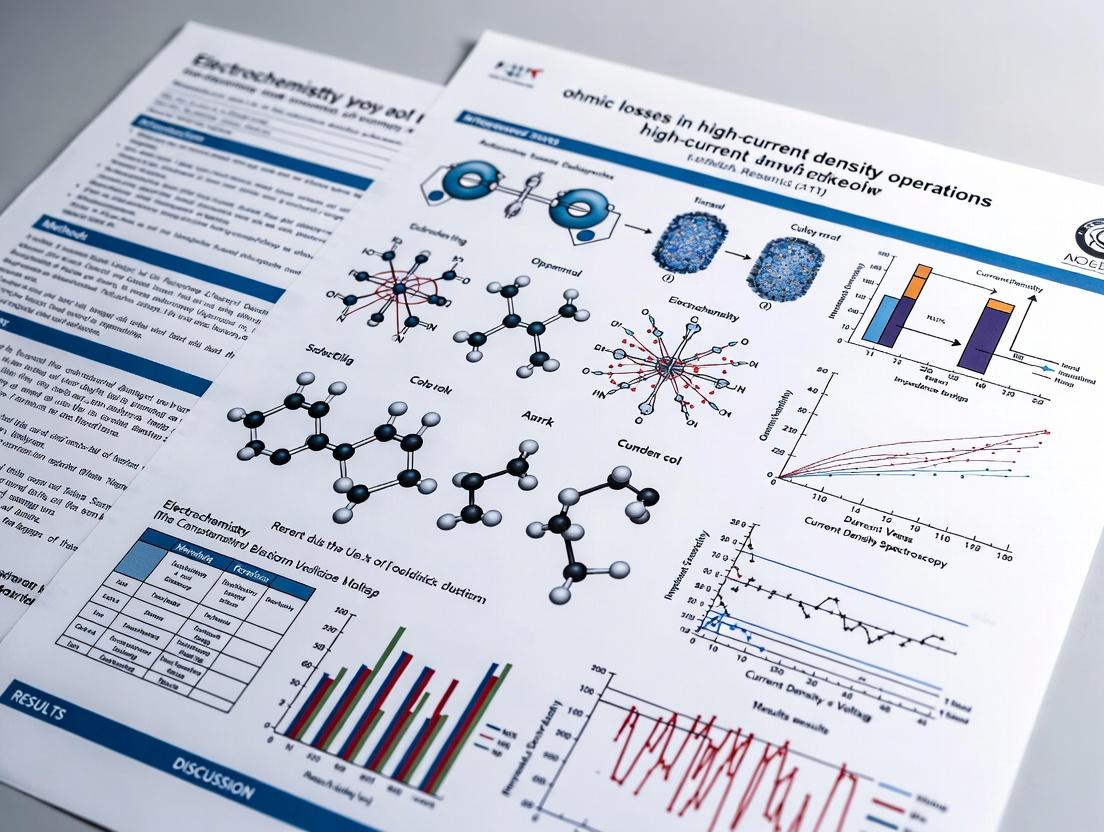
Mitigating Ohmic Losses in High-Current Density Operations: Strategies for Enhanced Efficiency and Device Performance
This article provides a comprehensive analysis of ohmic losses in high-current density systems, critical for researchers and development professionals in fields like electroporation for drug delivery and biosensing.
Mitigating Ohmic Losses in High-Current Density Operations: Strategies for Enhanced Efficiency and Device Performance
Abstract
This article provides a comprehensive analysis of ohmic losses in high-current density systems, critical for researchers and development professionals in fields like electroporation for drug delivery and biosensing. It explores the fundamental physics of resistive heating and voltage drop, reviews current mitigation strategies including advanced materials and cell design, offers practical troubleshooting and optimization methodologies, and validates approaches through comparative performance analysis. The synthesis aims to guide the development of more efficient and reliable biomedical devices.
Understanding Ohmic Losses: The Physics and Impact of Resistive Heating in High-Current Systems
Technical Support Center: Troubleshooting High-Current Density Experiments
Frequently Asked Questions (FAQs)
Q1: Our electrochemical reactor's temperature is rising uncontrollably during high-current pulses, despite active cooling. What is the primary cause? A: This is a classic symptom of excessive ohmic losses within the cell. According to Joule's first law (P = I²R), power loss is proportional to the square of the current and the cell's internal resistance. At high-current densities, even a small resistance in electrodes, interconnects, or electrolyte leads to significant heat generation. Ensure you have characterized the area-specific resistance (ASR) of all components at your operational temperature.
Q2: We observe inconsistent yield in our electrosynthesis batch process. Could ohmic losses be a factor? A: Yes. Inhomogeneous current distribution caused by localized high resistance (e.g., from poor electrode contact or degraded catalyst layers) leads to uneven reaction rates across the electrode surface. This results in batch-to-batch variability. Implement electrochemical impedance spectroscopy (EIS) to map charge-transfer and ohmic resistances.
Q3: Our lab-scale fuel cell performs well, but scaling up the stack leads to a severe voltage drop and hot spots. What should we investigate? A: Focus on contact resistance at interconnects and bipolar plates. As you scale, the number of interfaces multiplies. Microscopic imperfections create high-resistance points, concentrating current and heat (a "current funneling" effect). Review your stack compression force and interface coating materials.
Troubleshooting Guides
Issue: Sudden Voltage Drop in Flow Battery During High-Rate Charge.
- Symptoms: Terminal voltage drops sharply at high C-rates, accompanied by heat at one terminal.
- Diagnostic Steps:
- Measure Interconnect Temperature: Use an IR camera to identify localized heating at specific cell interconnects.
- Perform 4-Point Probe Measurement: Directly measure the resistance of suspect current collectors and busbars to isolate the high-resistance component.
- Inspect Contact Surfaces: Disassemble and check for corrosion, pitting, or insufficient compression on the identified hot interconnects.
- Solution: Clean all contact surfaces with an appropriate solvent and abrade to ensure freshness. Apply a thin, uniform layer of conductive anti-corrosion paste (e.g., silver-loaded or carbon-based). Reassemble, ensuring uniform torque on compression bolts as per the protocol below.
Issue: Non-uniform Electroplating in High-Throughput Electrodeposition Setup.
- Symptoms: Thicker deposition at the edges of the working electrode and varying morphology across the substrate.
- Diagnostic Steps:
- Model Current Distribution: Use simulation software (e.g., COMSOL) to model your cell geometry with the measured electrolyte conductivity.
- Characterize Electrolyte: Precisely measure electrolyte conductivity at operational temperature. Dilution or contamination can drastically increase ohmic loss.
- Verify Electrode Alignment: Misalignment between anode and cathode increases the current path, raising solution resistance.
- Solution: Implement a custom-designed, perforated or shaped counter electrode to achieve uniform field lines. Add a supporting electrolyte to increase ionic conductivity, ensuring it does not interfere with the reaction chemistry.
Experimental Protocols for Characterizing Ohmic Losses
Protocol 1: Area-Specific Resistance (ASR) Measurement via Current Interrupt Objective: To decouple and measure the ohmic (IR) drop in an electrochemical cell. Materials: Potentiostat/Galvanostat, high-current cell, high-speed data logger (>100 kHz). Method:
- Set the cell to a constant current density (j) relevant to your operation (e.g., 1 A/cm²).
- Once voltage stabilizes, trigger a rapid current interrupt (switch to open circuit) using the potentiostat's dedicated function.
- Record voltage at a high sampling rate. The instantaneous voltage jump at t=0 is the ohmic (IR) drop.
- Calculate ASROhmic = ΔVinstantaneous / j. Note: This method assumes the double-layer discharge is fast relative to the interrupt speed.
Protocol 2: Electrochemical Impedance Spectroscopy (EIS) for Component-Level Resistance Objective: To separate charge-transfer resistance from ohmic resistance in a full cell. Materials: Potentiostat with EIS capability, 2/3/4-electrode cell. Method:
- Set the cell to the desired DC bias potential/current.
- Apply a small AC perturbation (typically 10 mV) over a frequency range from 100 kHz to 0.1 Hz.
- Fit the resulting Nyquist plot to an equivalent circuit model (e.g., a Randles circuit).
- The high-frequency real-axis intercept is the total ohmic resistance (R_Ω), encompassing electrolyte, electrode, and contact resistances.
Table 1: Typical Ohmic Loss Contributions in Common High-Current Systems
| System Type | Typical Current Density | Primary Ohmic Source | Approx. Voltage Loss (IR Drop) | Mitigation Strategy |
|---|---|---|---|---|
| Alkaline Water Electrolyzer | 0.5 - 2.0 A/cm² | Ionic resistance of diaphragm | 200 - 400 mV | Use thinner, conductive membranes (e.g., Zirfon) |
| Li-Ion Battery (Charge) | 3 - 5 mA/cm² (Cell) | Solid-electrolyte interphase (SEI) & particle contact | 50 - 150 mV | Optimize electrode porosity & conductive additives |
| Microbial Electrolysis Cell | 5 - 20 A/m² | Anode biofilm & solution resistance | 300 - 600 mV | Use 3D porous anodes (e.g., carbon felt) |
| Fuel Cell (H₂-PEM) | 1 - 3 A/cm² | Proton conduction in membrane | 100 - 250 mV | Hydrate membrane, use thinner Nafion |
Table 2: Conductivity of Common Materials
| Material | Conductivity at 25°C (S/m) | Application | Note |
|---|---|---|---|
| Copper (OFHC) | 5.96 x 10⁷ | Current collectors, busbars | Industry standard for low resistance |
| Graphite (Dense) | 2.5 x 10⁴ to 1.0 x 10⁵ | Bipolar plates | Lightweight, corrosion-resistant |
| 1M KCl (Aqueous) | 1.1 x 10¹ | Reference electrolyte | Standard for calibrating conductivity cells |
| Nafion 117 (Hydrated) | ~10 | PEM Fuel Cell Membrane | Conductivity highly humidity-dependent |
| Carbon Felt | ~10² (bulk, anisotropic) | Porous Electrode | High surface area, good mass transport |
Visualizations
The Scientist's Toolkit: Key Research Reagent Solutions
Table 3: Essential Materials for Ohmic Loss Characterization
| Item / Reagent | Function | Key Consideration for Ohmic Loss |
|---|---|---|
| Conductive Paste (Ag or C-based) | Reduces contact resistance between bipolar plates, current collectors, and electrodes. | Ensure chemical compatibility with cell environment (e.g., acid resistance). |
| Reference Electrode (e.g., Ag/AgCl, Hg/HgO) | Enables precise measurement of working electrode potential, separating anode/cathode overpotentials. | Place Luggin capillary correctly to minimize inclusion of solution IR drop in measurement. |
| High-Conductivity Electrolyte Salt (e.g., LiClO₄, TBAPF₆) | Provides ionic charge carriers in non-aqueous or specialized electrochemical cells. | Concentration must be optimized—too high increases viscosity, too low increases resistance. |
| Nafion Membrane (varied thicknesses) | Standard proton-exchange membrane for PEM studies. Allows comparison of membrane resistance. | Pre-treatment (boiling in H₂O₂, acid, water) is critical for reproducible conductivity. |
| Conductive Additives (Carbon Black, Graphene) | Mixed with active materials to create conductive networks in composite electrodes. | Dispersion quality is paramount to avoid isolated, high-resistance catalyst particles. |
| Gold or Platinum Sputtering Target | For creating thin, uniform, highly conductive contact layers on insulating substrates for testing. | Film thickness must balance conductivity (thicker) with cost and catalyst masking (thinner). |
Technical Support & Troubleshooting Center
Frequently Asked Questions (FAQs)
Q1: During high-current density electroporation for drug delivery, my measured cell viability drops precipitously beyond a certain voltage threshold, despite calculations predicting lower ohmic heating. What could be causing this?
A: This is a classic sign of a nonlinear relationship between current density and resistivity. At high current densities, localized Joule heating can cause a significant, non-uniform temperature rise in your buffer or tissue. This temperature increase lowers the local resistivity (ρ = ρ₀[1 + α(T - T₀)]), which in turn allows even more current to flow in that region—a positive feedback loop. This "hotspot" formation leads to localized cell death beyond predictions from bulk-average calculations. Verify by using an IR camera to map temperature distribution in real-time.
Q2: My resistivity measurements of a biological hydrogel under DC conditions are inconsistent and drift over time. How can I stabilize readings?
A: Drift is often due to electrode polarization and electrochemical changes at the interface. Implement a 4-point probe (Kelvin) measurement technique to eliminate lead and contact resistance. Furthermore, avoid pure DC; use a low-frequency (e.g., 1-10 kHz) AC signal from a function generator coupled with a lock-in amplifier. This minimizes Faradaic reactions and ion buildup at electrodes. Ensure your electrolyte (hydrogel) is adequately buffered to maintain stable pH, as H⁺ and OH⁻ migration significantly impacts ionic conductivity.
Q3: When scaling up my electrochemotherapy protocol from in vitro to ex vivo tissue, the same applied electric field strength fails to achieve the desired current penetration. Why?
A: Tissue introduces complexity not seen in cell suspensions. Its resistivity is anisotropic (lower along fibers, higher across) and nonlinear. At higher field strengths, electroporation of membranes itself causes a dramatic nonlinear drop in resistivity as pores form, allowing more ionic current. However, in dense tissue, the current path may be shunted through conductive extracellular fluid or blood vessels, creating an inhomogeneous current density distribution. You must measure tissue impedance in situ prior to protocol finalization. Consider using pulsed waveforms with monitoring feedback to adapt to changing resistivity.
Troubleshooting Guides
Issue: Erratic Current Control in High-Density Microelectrode Arrays
- Symptoms: Current spikes, failure to maintain setpoint, electrode damage.
- Probable Cause 1: Solution resistivity change due to electrolysis and pH shifts.
- Action: Use buffered saline solutions and limit stimulation duration. Incorporate Ag/AgCl pellet electrodes or other non-polarizable electrodes if possible.
- Probable Cause 2: Contact failure leading to increased interfacial resistance.
- Action: Perform electrochemical impedance spectroscopy (EIS) on each electrode channel before experiments to identify failing contacts. Re-clean and re-plate (e.g., gold electroplating) electrodes as per protocol.
- Probable Cause 3: Software control loop instability from incorrect resistivity parameters.
- Action: Manually measure your bath's baseline resistivity with a conductivity meter and input the precise value into your stimulator's control software. Enable compliance voltage monitoring.
Issue: Nonlinear I-V Curve Deviation in Ionic Solution Measurements
- Symptoms: Current vs. Voltage plot deviates from linear Ohm's law prediction at moderate voltages.
- Diagnostic Steps:
- Check for Heating: Allow for long inter-pulse intervals and measure temperature.
- Check Electrodes: Switch from Pt wires to platinized Pt or Ag/AgCl to reduce overpotential.
- Check Ionic Composition: Dilute solutions or solutions with low buffer capacity exhibit earlier nonlinearity due to depletion of ions near electrodes (concentration polarization).
- Resolution: Characterize the full nonlinear I-V relationship for your specific system. For experimental protocols, operate within the linear region or develop a dynamic model that accounts for the nonlinearity.
Experimental Protocols
Protocol 1: Characterizing the Nonlinear Relationship Between Current Density and Bath Resistivity
Objective: To empirically determine how local resistivity changes as a function of applied current density in a conductive buffer.
Materials: (See "Scientist's Toolkit" below) Method:
- Set up a four-electrode cell in a temperature-controlled water bath (25°C). Place two outer current-injecting electrodes (Pt mesh) and two inner voltage-sensing electrodes (Ag/AgCl wires).
- Fill the cell with 1x PBS.
- Connect the current source to the outer electrodes. Connect a high-impedance voltmeter to the inner electrodes.
- Apply a series of 100ms DC current pulses with increasing amplitude, allowing 60s between pulses for temperature and ion concentration to re-equilibrate.
- For each pulse, record the stable current (I) and the measured voltage drop (V) between the inner probes.
- Calculate current density (J = I / A, where A is the cross-sectional area between inner probes) and apparent resistivity (ρ = (V * A) / (I * d), where d is the distance between voltage probes).
- Plot ρ vs. J. Repeat at different base temperatures (4°C, 37°C).
Protocol 2: In-situ Impedance Monitoring During High-Censity Pulsed Operation
Objective: To detect the onset of nonlinear effects and electroporation in real-time during a pulse protocol.
Materials: Bipolar constant-current pulse generator, high-speed digitizer, oscilloscope, custom-built electrode chamber. Method:
- Configure your pulse generator to deliver the desired therapeutic or experimental pulse train (e.g., 8x 100µs square pulses).
- Using a current probe or a small series resistor, route the voltage signal across the sample and the current signal to a high-speed digitizer (sampling rate >1 MHz).
- For each pulse, plot the instantaneous voltage divided by instantaneous current to calculate dynamic resistance.
- Observe the trace. A flat resistance indicates ohmic behavior. A monotonic decrease within a single pulse indicates membrane electroporation or heating. A sharp spike indicates electrode polarization.
- Use this dynamic resistance profile to adjust pulse parameters between bursts to manage ohmic losses.
Data Presentation
Table 1: Resistivity of Common Biological Solutions & Tissues (Approximate, 20-37°C)
| Material | Approx. Resistivity (Ω·cm) | Notes on Nonlinearity |
|---|---|---|
| 1x Phosphate Buffered Saline (PBS) | ~70 Ω·cm | Linear up to ~100 A/m²; nonlinearity from heating >50°C. |
| Standard Cell Culture Medium | ~90 Ω·cm | More complex due to organics; pH shifts cause nonlinear drift. |
| Skeletal Muscle (transverse) | ~2000 Ω·cm | Highly nonlinear; drops 5-10x upon electroporation. |
| Liver Tissue | ~1500 Ω·cm | Anisotropic; significant decrease with pulse application. |
| 0.9% Saline | ~60 Ω·cm | Highly linear across broad range. |
Table 2: Impact of Key Parameters on Ohmic Loss (P = J² * ρ)
| Parameter Increase | Direct Effect on Ohmic Loss | Secondary Nonlinear Effect |
|---|---|---|
| Current Density (J) | Loss increases with square of J. | Heating reduces ρ, potentially allowing even higher J in hotspots. |
| Solution Resistivity (ρ) | Loss increases linearly with ρ. | Higher ρ leads to greater voltage need for same J, increasing polarization. |
| Pulse Duration | Longer duration increases total energy (heat). | Allows time for thermal diffusion and ion migration, changing local ρ. |
| Electrode Area | Increases for constant J (more total current). | Can mitigate by reducing current density per unit area. |
The Scientist's Toolkit
Key Research Reagent Solutions & Materials
| Item | Function in Experiment |
|---|---|
| Ag/AgCl Electrode Pellets | Provides stable, non-polarizable reference voltage point; minimizes overpotential for accurate resistivity measurement. |
| Four-Point Probe Fixture | Eliminates the influence of contact and wire resistance, which is critical for measuring intrinsic resistivity of materials. |
| Low-Conductivity Buffer (e.g., Sucrose-Based) | Used to isolate current pathways through cells (in electroporation) rather than the surrounding medium. |
| Infrared Thermal Camera | Visualizes non-uniform heating and hotspot formation caused by nonlinear current flow. |
| Lock-in Amplifier | Precisely measures impedance and phase of a sample by detecting a specific frequency, rejecting noise. |
| Platinizing Solution (e.g., Pt black) | Coating Pt electrodes increases effective surface area, reducing current density at the interface and delaying polarization. |
Visualizations
Title: Nonlinear Feedback Loop of Current Density and Resistivity
Title: 4-Point Probe Method for Accurate Resistivity
Welcome to the Technical Support Center for the research initiative: Addressing Ohmic Losses in High-Current Density Operations. This center provides targeted troubleshooting and FAQs for common experimental challenges.
Troubleshooting Guides & FAQs
Q1: During high-current pulse testing of our electrochemical cell, we observe excessive and uneven heating at the current collectors. What are the primary causes and immediate corrective actions?
A: Excessive localized heating typically indicates non-uniform current distribution due to:
- Poor interfacial contact: Imperfect alignment or pressure between the electrode, separator, and current collector.
- Current collector corrosion/degradation: Formation of high-resistance oxide layers on metallic foils (e.g., Al, Cu).
- Non-homogeneous electrode coating: Variations in electrode thickness or porosity create preferential high-current pathways.
Immediate Protocol:
- Interrupt the test and allow the cell to cool to ambient temperature in a controlled environment.
- Disassemble the cell in an inert atmosphere glovebox and visually inspect components.
- Measure the surface resistivity of the current collector foil at multiple points using a 4-point probe. Variance >5% indicates a material or contamination issue.
- Re-assemble with calibrated torque to ensure even pressure distribution, using a fresh separator.
Q2: Our system experiences significant voltage sag under load, reducing the effective working voltage window. How can we isolate the source of the ohmic loss (IR drop)?
A: Voltage sag (ΔV = I * R) must be diagnostically separated into components. Follow this Electrochemical Impedance Spectroscopy (EIS) protocol pre- and post-high-current cycling.
Experimental Protocol: EIS for IR Drop Isolation
- Equipment: Potentiostat with EIS capability, frequency range 100 kHz to 0.1 Hz, AC amplitude of 10 mV, at the cell's open-circuit voltage.
- Procedure:
- Stabilize the cell at the target operating temperature (e.g., 25°C).
- Perform EIS on a fresh cell to establish a baseline.
- Subject the cell to defined high-current cycles (e.g., 5C charge/discharge for 100 cycles).
- Perform EIS again under identical conditions.
- Analysis: The high-frequency real-axis intercept in the Nyquist plot represents the total ohmic resistance (RΩ). An increase points to degradation in bulk electrolytes, current collectors, or interfaces.
Q3: We have quantified ohmic losses, but the overall system energy efficiency continues to decline faster than modeled. What factors beyond simple resistance should we investigate?
A: Efficiency reduction (η) is multi-factorial. While ohmic heat (I²R) is key, you must also evaluate:
- Polarization Losses: Activation and concentration overpotentials that increase disproportionately at high rates.
- Coulombic Inefficiency: Side reactions (e.g., electrolyte decomposition, gas generation) accelerated by local heat.
Experimental Protocol: Differential Voltage Analysis (dQ/dV)
- Procedure: Perform a low-rate (C/20) diagnostic charge-discharge cycle on the aged cell.
- Data Processing: Plot dQ/dV versus Voltage. Compare peak positions and amplitudes to a baseline cell.
- Interpretation: Shifting or diminished peaks indicate loss of active lithium or active material, linking efficiency drop to degradation mechanisms exacerbated by ohmic heating.
Table 1: Common Current Collector Properties & Performance
| Material | Typical Thickness (μm) | Bulk Resistivity (μΩ·cm) | Max Stable Potential vs. Li/Li+ | Key Vulnerability in High-Current Operations |
|---|---|---|---|---|
| Copper (Cu) | 10 - 20 | 1.68 | ~0.3 V (Reduction) | Anodic dissolution above ~3.5V; pitting at high local J. |
| Aluminum (Al) | 15 - 25 | 2.65 | ~1.8 V (Oxidation) | Resistive Al₂O₃ layer growth; localized corrosion. |
| Carbon-coated Al | 20 - 30 | 3 - 10 | ~4.5 V (Oxidation) | Coating delamination under thermal cycling. |
Table 2: Impact of Current Density on Measured Parameters in a Model Li-ion Pouch Cell
| Current Density (mA/cm²) | Measured RΩ Increase (Post-100 cycles) | Average Temp Rise at Terminal (°C) | Capacity Retention (%) | Energy Efficiency (Dis/Chg, %) |
|---|---|---|---|---|
| 5 (Baseline) | 5% | 4.2 | 98.5 | 99.1 |
| 15 | 18% | 12.8 | 95.1 | 97.3 |
| 30 | 42% | 31.5 | 88.7 | 92.4 |
Experimental Workflow & Pathways
Title: High-Current Experiment Troubleshooting Pathway
The Scientist's Toolkit: Research Reagent Solutions
Table 3: Essential Materials for High-Current Loss Research
| Item | Function & Specification | Rationale for Use |
|---|---|---|
| 4-Point Probe Setup | Measures sheet resistance of current collector foils. Tip spacing ≤ 1 mm. | Critical for quantifying spatial uniformity of collector resistivity before/after cycling. |
| Electrochemical Impedance Spectrometer | Frequency range: 10 µHz to 10 MHz. | Gold standard for deconvoluting ohmic (Rs), charge-transfer (Rct), and diffusion (W) resistances. |
| Infrared Thermal Camera | Sensitivity: < 0.05°C; Spatial resolution: ≤ 50 µm/pixel. | Visualizes localized "hot spots" from poor contact or current crowding in real-time. |
| Lithium Bis(oxalato)borate (LiBOB) Electrolyte Additive | 0.5 - 1.0 wt.% in LiPF₆-based electrolyte. | Forms a stable, low-resistance SEI on anodes and protective film on Al cathodic collectors, mitigating corrosion. |
| Carbon-Coated Aluminum Foil | Coating thickness: 1-5 µm; Surface resistance: < 20 Ω/sq. | Provides a conductive, passivating layer to suppress resistive Al₂O₃ growth and enhance adhesion. |
| Polyimide (Kapton) Tape Shims | Precise thickness (e.g., 25, 50, 100 µm). | Used to calibrate and apply uniform stack pressure in pouch or coin cells, ensuring reproducible interfacial contact. |
Technical Support Center
Troubleshooting Guides & FAQs
Section 1: Electroporation & High-Current Density Operations
Q1: During in vitro electroporation of adherent cells, we observe excessive arcing and cell death, even at standard parameters. What could be the cause and solution within the context of minimizing ohmic losses?
- A: This is often due to high interfacial impedance and bubble formation at the electrode-solution interface, leading to localized current surges (arcing). To address this:
- Use Phosphate-Buffered Saline (PBS) or specialized electroporation buffers with sufficient ionic strength (e.g., 100-150 mM NaCl) to reduce solution resistance (R_s). Avoid low-conductivity media like pure water or sugar solutions.
- Implement platinum or aluminum electrodes instead of stainless steel for better corrosion resistance and stable interface impedance.
- Apply a biphasic or oscillating pulse waveform. This can help mitigate polarization at the electrodes, reducing gas bubble formation and stabilizing current delivery.
- Ensure electrodes are parallel and evenly spaced. Non-uniform gaps create regions of high current density, leading to localized heating and arcing.
- A: This is often due to high interfacial impedance and bubble formation at the electrode-solution interface, leading to localized current surges (arcing). To address this:
Q2: Our lab-on-a-chip electroporation device shows inconsistent transfection efficiency across different chambers. We suspect non-uniform electric field distribution. How can we diagnose and correct this?
- A: Inconsistent fields often stem from uneven channel geometry or electrode degradation, exacerbating ohmic losses in some areas.
- Diagnosis: Use a fluorescent dye (e.g., propidium iodide) and image the electric field distribution indirectly via dye uptake uniformity. Alternatively, measure impedance across different chambers.
- Solutions:
- Redesign the microfluidic channel to ensure consistent cross-sectional area between electrodes.
- Incorporate integrated, transparent electrodes (e.g., Indium Tin Oxide - ITO) for uniform current distribution and real-time microscopy.
- Implement constant current (rather than constant voltage) pulse control. This compensates for minor variations in inter-electrode resistance, delivering a more consistent dose.
- A: Inconsistent fields often stem from uneven channel geometry or electrode degradation, exacerbating ohmic losses in some areas.
Section 2: Electrical Stimulation Devices
- Q3: In chronic neural stimulation experiments, our electrode impedance increases steadily over time, requiring higher voltage to maintain stimulus amplitude. How can we mitigate this to prevent tissue damage from high-voltage operation?
- A: Increasing impedance is typically due to fibrotic encapsulation and electrode fouling, which increases the access resistance (R_a) and thus ohmic losses.
- Protocol for Mitigation:
- Pre-experiment Coating: Coat electrodes with conductive polymers like PEDOT:PSS or hydrogel layers. This increases the effective surface area, lowers interfacial impedance, and reduces inflammatory response.
- Cleaning Protocol: Periodically apply short, high-frequency cathodic pulses (e.g., 1-10 µA, 200 Hz, 30 sec) in a saline solution to reduce protein fouling without damaging the electrode.
- Monitor and Adjust: Use an impedance-tracking system to adjust stimulation parameters within safe charge injection limits, switching to constant-current mode if not already used.
- Protocol for Mitigation:
- A: Increasing impedance is typically due to fibrotic encapsulation and electrode fouling, which increases the access resistance (R_a) and thus ohmic losses.
Section 3: Lab-on-a-Chip General Operation
- Q4: Our microfluidic drug screening assay yields highly variable results. We suspect inconsistent flow rates and shear stress due to pump pulsation or bubble obstruction. How do we stabilize operation?
- A: Variability undermines assay precision. Key steps:
- Bubble Removal Protocol: Integrate an on-chip degasser or a "bubble trap" chamber upstream of critical features. Pre-flush all channels with a degassed buffer (e.g., by sonicating buffer under vacuum for 20 minutes).
- Pulsation Dampening: For syringe pumps, use compliant tubing (e.g., silicone) between the pump and chip inlet as a passive pulse damper. Alternatively, switch to pressure-driven flow controllers with integrated feedback sensors.
- Prime the system at a high flow rate (e.g., 100 µL/min) for 5 minutes before dropping to the low experimental flow rate to ensure all channels are uniformly wetted and bubbles are purged.
- A: Variability undermines assay precision. Key steps:
Table 1: Common Buffer Conductivities and Associated Electroporation Parameters
| Buffer Solution | Ionic Strength (approx.) | Conductivity (mS/cm) | Typical Field Strength for Mammalian Cells | Pulse Length | Relative Cell Viability Post-Pulse |
|---|---|---|---|---|---|
| Standard PBS | ~150 mM | 15 - 17 | 0.5 - 1.0 kV/cm | 1 - 10 ms | 70 - 85% |
| Opti-MEM | Low | 1 - 2 | 0.2 - 0.5 kV/cm | 0.1 - 5 ms | 80 - 95% |
| Cytoporation Medium | High | 10 - 12 | 0.3 - 0.8 kV/cm | 5 - 20 ms | 60 - 80% |
| Sucrose (0.25M) with Mg²⁺ | Very Low | 0.05 - 0.1 | 1.0 - 2.5 kV/cm | 0.01 - 0.1 ms | 75 - 90% |
Table 2: Electrode Materials for Biomedical Devices
| Material | Charge Injection Limit (µC/cm²) | Corrosion Resistance in Saline | Key Application | Impact on Ohmic Loss |
|---|---|---|---|---|
| Platinum (Pt) | 100 - 300 | Excellent | Neural Stimulation, Chronic Implants | Low, stable interface |
| Platinum-Iridium (PtIr) | 150 - 500 | Excellent | Deep Brain Stimulation Electrodes | Very Low |
| ITO (Indium Tin Oxide) | 10 - 50 | Good (for short-term) | Transparent LOC Electrodes | Medium, can increase with cycling |
| Stainless Steel 316L | 40 - 100 | Moderate (prone to pitting) | Temporary Probes, In vitro devices | Can increase significantly due to corrosion |
| Conductive Polymer (PEDOT:PSS) | 1 - 10 | Good (mechanical fatigue) | High-Surface Area Coatings | Very Low, reduces access resistance |
Experimental Protocols
Protocol 1: Measuring Interface Impedance for Electrode Characterization Objective: Quantify the impedance spectrum of a stimulation/electroporation electrode to assess its condition and predict ohmic losses.
- Setup: Connect the working electrode and a large Pt counter electrode to a potentiostat/impedance analyzer in a three-electrode configuration with Ag/AgCl reference.
- Environment: Immerse electrodes in 1x PBS at 37°C (simulating physiological conditions).
- Measurement: Apply a 10 mV RMS sinusoidal signal across a frequency range of 0.1 Hz to 100 kHz. Log the impedance magnitude (|Z|) and phase angle (θ).
- Analysis: Plot Nyquist (complex plane) and Bode plots. The high-frequency real-axis intercept estimates the solution resistance (Rs). The diameter of the semicircular arc represents the charge transfer resistance (Rct). An increasing R_ct indicates fouling or degradation.
Protocol 2: Calibrating On-Chip Electric Field Distribution via Fluorescent Dye Objective: Visually map electric field uniformity in a microfluidic electroporation device.
- Dye Solution: Prepare a 100 µM solution of Propidium Iodide (PI) in a low-conductivity electroporation buffer (e.g., 10% PBS in isotonic sucrose).
- Load and Flow: Introduce the PI solution into the device and stop flow.
- Pulse Application: Apply a single, standard electroporation pulse (e.g., 50 V, 5 ms).
- Imaging: Immediately capture a fluorescence image using a standard TRITC filter set. The local fluorescence intensity is proportional to PI uptake, which is a function of the local transmembrane potential induced by the electric field.
- Analysis: Use image analysis software (e.g., ImageJ) to plot a line profile of fluorescence intensity across the channel width. A flat profile indicates uniform field distribution.
Visualizations
Diagram 1: Ohmic Loss Components in a Bio-Electrical Interface
Diagram 2: Standard Workflow for Troubleshooting Electroporation Efficiency
The Scientist's Toolkit: Research Reagent Solutions
| Item | Function in Context | Key Consideration for Ohmic Losses |
|---|---|---|
| Platinizing Solution (e.g., 3% Chloroplatinic Acid) | To electroplate platinum black onto electrodes, drastically increasing surface area and charge injection capacity. | Reduces charge transfer resistance (R_ct), minimizing voltage drop at the interface. |
| PEDOT:PSS Dispersion | A conductive polymer used to coat neural or stimulation electrodes via electrodeposition or drop-casting. | Lowers interfacial impedance, enables safer, more efficient charge delivery at lower voltages. |
| Degassed, Low-Conductivity Buffer (e.g., 10% PBS in 0.25M Sucrose) | Standard solution for in vitro electroporation of sensitive cell types. | Reduces bulk solution resistance (R_s) and Joule heating, while providing sufficient ions for membrane charging. |
| Propidium Iodide (PI) / YO-PRO-1 Dye | Membrane-impermeant fluorescent dyes used to visualize successful electroporation (pore formation) in real time. | Serves as a diagnostic tool for field uniformity, indirectly assessing if ohmic losses are causing "cold spots". |
| Electrode Impedance Testing Kit (Potentiostat, PBS, Ag/AgCl reference) | For routine monitoring of electrode health and interface characteristics. | Directly measures Rs and Rct, allowing preemptive maintenance before ohmic losses compromise experiments. |
| Polydimethylsiloxane (PDMS) | The predominant elastomer for rapid prototyping of microfluidic (LOC) devices. | Its hydrophobic surface can trap bubbles, increasing resistance; plasma treatment is essential for stable wetting. |
| Indium Tin Oxide (ITO) Coated Slides | Provide transparent, conductive substrates for integrated electrodes in imaging-compatible LOC devices. | Sheet resistance (∼10-20 Ω/sq) contributes to series resistance; design must account for voltage drop along the electrode. |
Strategies and Materials for Minimizing Electrical Resistance in Device Design
Troubleshooting Guide & FAQ
FAQ: General Material Properties & Selection
Q1: For a high-current density microelectrode array in electrophysiology, which material offers the best compromise between ultra-low resistivity, electrochemical stability, and ease of fabrication?
A: Sputtered Gold (Au) or Platinum (Pt) on an adhesion layer (e.g., Titanium or Chromium) remains the benchmark. While graphene and CNTs have superior theoretical current-carrying capacity, metals offer proven stability in saline (PBS) environments and standardized fabrication. For DC or low-frequency AC, use Au. For higher frequencies where skin effect matters, consider electroplated silver.
Q2: My CVD-grown graphene film shows higher sheet resistance than literature values. What are the primary culprits?
A: This typically stems from:
- Polycrystalline Grain Boundaries: Defects between graphene grains scatter charge carriers.
- Polymer Residue (PMMA): Incomplete removal from the transfer process.
- Doping Variations: Unintentional doping from substrate or atmosphere (H₂O, O₂).
- Wrinkles and Cracks: Mechanical damage during transfer.
Troubleshooting Protocol: Perform a stepwise analysis: 1. Measure sheet resistance (4-point probe) and carrier mobility (Hall effect). 2. Use Raman spectroscopy (peaks: D-defect, G, 2D) to quantify defect density. 3. Anneal in Ar/H₂ at 300-400°C to remove residues and improve contact.
Q3: During CNT forest growth via PECVD, the density is inconsistent, leading to high contact resistance. How can I improve uniformity?
A: Inconsistent density often results from non-uniform catalyst nanoparticle formation. Protocol for Sputtered Catalyst (Fe/Al₂O₃ on Si): 1. Ensure Al₂O₃ support layer is uniformly thick (10-15 nm). 2. Anneal the Fe catalyst layer in a reducing environment (H₂/Ar) in-situ prior to C₂H₄ introduction to form uniform nanoparticles. 3. Precisely control substrate temperature gradient (<5°C variation across wafer).
FAQ: Integration & Measurement Issues
Q4: I am experiencing severe Joule heating and rapid degradation at the metal-CNT interface in my high-current test structure.
A: This is a classic interfacial ohmic loss problem. Solution Protocol: 1. Interface Engineering: Use a Ti or Cr adhesion layer and a diffusion barrier (e.g., Pd or Ni) before the Au top contact to prevent carbide formation. 2. Contact Doping: Functionalize the CNT ends with AuCl₃ or HNO₃ to p-dope the contact region, lowering the Schottky barrier. 3. Geometry: Design the contact overlap area to be maximized to distribute current.
Q5: My measured resistivity for a copper nanowire network is orders of magnitude higher than bulk copper. Is this due to material quality or measurement error?
A: Likely both. For nanostructures, surface scattering and contact resistance dominate. Diagnostic Experimental Workflow: 1. Perform 4-point probe measurement on the network to eliminate probe contact resistance. 2. Use Transmission Line Method (TLM) structures to deconvolute the intrinsic nanowire resistance from the metal-nanowire contact resistance. 3. Characterize surface oxidation via XPS; even a 2-3 nm Cu₂O layer drastically increases resistance.
Quantitative Data Comparison: Key Conductive Materials
Table 1: Intrinsic Electrical Properties of Advanced Conductors
| Material | Bulk Resistivity (μΩ·cm) @ 20°C | Current Carrying Capacity (A·cm⁻²) | Mean Free Path (nm) @ RT | Key Advantages | Primary Limitation for Integration |
|---|---|---|---|---|---|
| Silver (Ag) | 1.59 | > 1 x 10⁷ (electromigration limit) | ~52 | Lowest bulk resistivity, high conductivity | Sulfidation, electromigration, cost |
| Copper (Cu) | 1.68 | ~1 x 10⁷ | ~40 | Standard IC interconnect, cost-effective | Oxidation, diffusion into substrates |
| Gold (Au) | 2.44 | ~5 x 10⁶ | ~37 | Chemically inert, excellent stability | High cost, lower conductivity than Ag/Cu |
| Graphene (SLG) | ~1 (Sheet Res.: Ω/sq) | ~1 x 10⁹ (ballistic) | 1000s (ballistic) | High mobility, 2D flexibility, transparent | Batch-to-batch variability, contact resistance |
| SWCNT (Metallic) | ~10⁻⁴ (per tube) | ~1 x 10⁹ (ballistic) | 1000s (ballistic) | 1D ballistic transport, high thermal conductivity | Chirality control, bundling, junction resistance |
Table 2: Comparative Performance in High-Current Density Test Structures (Simulated)
| Material System | Measured Jmax (A·cm⁻²) @ Failure | Dominant Failure Mode | Critical Thermal Management Step |
|---|---|---|---|
| Electroplated Ag on Si | 5.2 x 10⁶ | Electromigration voiding | Use a refractory metal barrier layer (TaN) |
| CVD Graphene on Cu | 2.1 x 10⁸ (pulsed) | Localized thermal oxidation | Encapsulation with h-BN for heat spreading |
| Aligned CNT Bundle | 1.5 x 10⁹ (pulsed) | Joule heating at metal-CNT contact | End-bonded contact (Ni-C carbide formation) |
| Sputtered Cu with Graphene Cap | 8.7 x 10⁶ | Surface scattering reduction | 2-layer graphene capping to suppress Cu diffusion |
Experimental Protocols
Protocol 1: Four-Point Probe Sheet Resistance Measurement for Thin Films
Objective: Accurately measure the sheet resistance (Rₛ) of a conductive film (graphene, metal) excluding contact resistance. Reagents/Materials: Sample on insulating substrate, 4-point probe head, semiconductor parameter analyzer. Method: 1. Align four collinear, equally spaced (s) probe tips onto the film. 2. Force a constant current (I) between the two outer probes. 3. Measure the voltage drop (V) between the two inner probes. 4. Calculate sheet resistance: Rₛ = (π/ln2) * (V/I) ≈ 4.532 * (V/I) for a thin film on an insulating substrate. Validation: Measure a standard reference sample.
Protocol 2: Transfer Line Method (TLM) for Contact Resistance Extraction
Objective: Determine the specific contact resistivity (ρc) between a metal and a conductive channel (CNT, graphene). Method: 1. Fabricate a series of identical conductive channels with varying lengths (L) but identical metal contact areas. 2. Measure the total resistance (RT) for each device via two-terminal I-V. 3. Plot RT vs. Channel Length (L). The y-intercept is 2RC (twice the contact resistance). The slope gives the sheet resistance per square of the channel. 4. Calculate ρc using the transfer length (LT) model.
Visualizations
Diagram 1: Ohmic Loss Troubleshooting Decision Tree
Diagram 2: Contact Analysis via Transfer Line Method
The Scientist's Toolkit: Key Research Reagent Solutions
| Item | Function & Application in Conductivity Research |
|---|---|
| Polymethyl Methacrylate (PMMA) A4 | Sacrificial polymer layer for wet-transfer of CVD graphene, offering clean release and minimal residue. |
| Chlorobenzene | Solvent for resist processing and effective removal of PMMA residues in graphene transfer (hot bath). |
| Gold(III) Chloride (AuCl₃) | Common p-type doping agent for graphene and CNTs; improves metal contact by lowering Schottky barrier. |
| Boron Nitride Nanotubes (BNNTs) | Used as insulating, high-thermal conductivity fillers in composite conductors to manage heat. |
| Cyclopentyl Methyl Ether (CPME) | Green solvent for dispersing CNTs with minimal bundling, aiding in uniform film deposition. |
| (3-Aminopropyl)triethoxysilane (APTES) | Silane coupling agent to improve adhesion between metal oxides and graphene on substrates. |
| Hydrazine Vapor (N₂H₄) | Reducing agent for reduced Graphene Oxide (rGO) films, restoring sp² bonds and conductivity. |
| Ferrocene (in Xylene) | Common precursor solution for floating-catalyst CVD growth of carbon nanotube forests. |
Technical Support Center: Troubleshooting and FAQs
FAQ: General Principles & High-Current Context
Q1: Within the thesis on addressing ohmic losses, why are electrode geometry and interface engineering the primary levers for improvement? A1: Ohmic losses (I²R) scale with the square of current density. At high currents, even small resistances generate significant heat and voltage drop, reducing efficiency and stability. Optimizing geometry (e.g., increasing surface area) reduces current density per unit area, while coatings and contact engineering directly lower the interfacial resistance (R), mitigating the primary source of loss.
Q2: What are the first experimental signs of excessive interfacial ohmic loss? A2: Key observable signs include:
- A significant voltage drop at the onset of current flow in polarization curves.
- Poor rate capability—rapid capacity/performance fade as current density increases.
- Abnormal heating localized at the electrode connections or active surface.
- Nonlinear or non-ideal behavior in electrochemical impedance spectroscopy (EIS) spectra, specifically a large, distorted high-frequency semicircle.
Troubleshooting Guide: Common Experimental Issues
Issue 1: High and Unstable Contact Resistance in a Custom Cell Setup
- Symptoms: Erratic voltage readings, poor reproducibility between identical experiments, excessive heat at connectors.
- Diagnostic Protocol:
- Perform a four-point probe (Kelvin) measurement on the assembled cell/connection to isolate the contact resistance from the material/bulk resistance.
- Conduct EIS from 100 kHz to 1 Hz. A large, sloping 45° line or a depressed semicircle at the highest frequencies indicates poor contact or current distribution.
- Solutions:
- Surface Preparation: Mechanically abrade contact points with fine sandpaper, followed by ultrasonic cleaning in isopropanol.
- Contact Force: Apply consistent, calibrated pressure using a torque screwdriver or spring-loaded contacts. Refer to Table 1 for guidelines.
- Interlayer: Use a soft, conductive interlayer (e.g., gold-plated copper foil, conductive carbon paste, or indium foil) between the electrode and current collector.
Issue 2: Rapid Performance Degradation of a Coated Electrode at High Current Density
- Symptoms: Initial performance is good but decays sharply within a few cycles at elevated C-rates.
- Diagnostic Protocol:
- Perform post-mortem SEM/EDS analysis of the electrode surface to check for coating delamination, cracking, or dissolution.
- Use Operando EIS or periodic EIS during cycling to track the increase in charge transfer resistance (Rct) and surface film resistance (Rf).
- Solutions:
- Coating Adhesion: Ensure the substrate is thoroughly cleaned and oxidized (if needed) to promote coating adhesion. Consider adding an adhesion promoter layer.
- Coating Morphology: Switch from a dense, thick coating to a conformal, thin, or porous coating (e.g., using ALD instead of dip-coating) to accommodate strain during ion insertion/extraction.
- Mechanical Properties: Select a coating material with a better modulus match to the active material to prevent fracture.
Issue 3: Inhomogeneous Current Distribution Due to Poor Electrode Geometry
- Symptoms: "Edge effects" or localized heating, non-uniform plating/stripping, lower-than-theoretical capacity.
- Diagnostic Protocol:
- Use infrared (IR) thermography during operation to visualize hot spots.
- Employ scanning electrochemical microscopy (SECM) to map local current variations across the electrode surface.
- Solutions:
- Design Optimization: Implement interdigitated, fractal, or mesh electrode geometries to maximize accessible surface area and shorten ion diffusion paths. See Diagram 1 for a comparison.
- Current Collector Integration: Use a 3D porous current collector (e.g., carbon foam, metal mesh) to improve penetration and distribution of current.
Experimental Protocols
Protocol 1: Measuring Area-Specific Resistance (ASR) of a Coated Interface Objective: Quantify the contribution of a surface coating to total interfacial resistance.
- Sample Prep: Deposit coating via sputtering/ALD on a polished, conductive substrate. Mask a known area (e.g., 1 cm²).
- Cell Assembly: Assemble a symmetric cell (Coating/Electrolyte/Coating) in a test fixture with calibrated pressure.
- EIS Measurement: Measure impedance (1 MHz to 0.1 Hz, 10 mV amplitude). Fit the high-frequency intercept with the real axis (Z') to obtain the total ASR.
- Calculation: Subtract the ASR of an identical uncoated control cell from the coated cell ASR to isolate the coating's contribution.
Protocol 2: Optimizing Contact Pressure for a Bolt-Clamped Cell Objective: Determine the minimum uniform pressure for low, stable contact resistance.
- Instrumentation: Use a torque screwdriver and a cell with pressure-sensitive film or an embedded load cell.
- Procedure: Assemble cell with standard components. Apply torque in incremental steps (e.g., 0.2, 0.5, 1.0 Nm). At each step, measure contact resistance via 4-point probe.
- Analysis: Plot contact resistance vs. applied pressure. Identify the pressure plateau where resistance stabilizes—this is the optimal minimum pressure.
Data Presentation
Table 1: Optimal Contact Pressure Ranges for Common Materials
| Material Pair | Recommended Pressure Range | Typical Application | Notes |
|---|---|---|---|
| Stainless Steel / Graphite | 5 - 15 MPa | Li-ion Cell Testing | Avoid >20 MPa to prevent particle fracture. |
| Aluminum / LCO Cathode | 8 - 12 MPa | Coin Cell Assembly | Use Al springs for consistent force. |
| Copper / Silicon Anode | 2 - 5 MPa | Half-cell Testing | Lower pressure to accommodate volume expansion. |
| Gold-plated Cu / Solid Electrolyte | 10 - 25 MPa | All-Solid-State Battery | Higher pressure ensures intimate contact. |
Table 2: Impact of Coating Techniques on Interfacial Resistance
| Coating Method | Typical Thickness | Conformal? | Resulting ASR Reduction (vs. bare) | Key Limitation |
|---|---|---|---|---|
| Atomic Layer Deposition (ALD) | 2-50 nm | Excellent | 60-90% | Slow, high cost, batch processing. |
| Magnetron Sputtering | 50-500 nm | Good (line-of-sight) | 40-80% | Pinhole defects, poor edge coverage. |
| Chemical Vapor Deposition (CVD) | 20-200 nm | Good | 50-85% | High temperature may damage substrate. |
| Electrodeposition | 100-2000 nm | Poor | 30-70% | Requires conductive substrate, thickness control. |
| Spray Pyrolysis | 500-5000 nm | Poor | 20-50% | Porous, non-dense layers. |
Visualizations
Diagram 1: Geometry effects on current density distribution.
Diagram 2: Decision tree for addressing interfacial ohmic losses.
The Scientist's Toolkit: Research Reagent Solutions
| Item / Reagent | Primary Function in Electrode/Interface Engineering |
|---|---|
| Lithium Bis(trifluoromethanesulfonyl)imide (LiTFSI) | High-concentration electrolyte salt for forming stable, LiF-rich SEI/CEI layers, reducing interfacial resistance. |
| Vinylene Carbonate (VC) & Fluoroethylene Carbonate (FEC) | Electrolyte additives that polymerize to form flexible, conductive polymeric interface layers, improving cycle life at high current. |
| Aluminum Oxide (Al₂O₃) ALD Precursor (TMA, H₂O) | Creates ultrathin, conformal protective coatings on cathode/anode particles to suppress parasitic reactions and side products. |
| Conductive Carbon Paste (e.g., Carbon Cement) | Provides a low-resistance, adhesive electrical connection for sensitive materials (e.g., powders) to current collectors. |
| Indium Foil / Gallium-Indium-Tin Eutectic (EGaIn) | Soft, malleable metal interlayers that cold-weld to surfaces, ensuring maximum contact area and minimizing contact resistance. |
| Nafion Binder Solution | Ion-conductive binder for electrode fabrication, promoting ion accessibility at high rates and enhancing adhesion. |
| Atomic Layer Deposition (ALD) System | Equipment for depositing pinhole-free, angstrom-precise ceramic or metal coatings on complex geometries. |
| Torque Screwdriver Set | Applies precise, reproducible pressure to cell hardware, critical for minimizing and standardizing contact resistance. |
Troubleshooting Guide & FAQs for High-Current Density Experiments
This technical support center is designed to assist researchers and scientists working on mitigating ohmic losses in high-current density operations, particularly in applications like electroporation for drug development or advanced material synthesis. The following guides address common experimental pitfalls.
FAQ: Common Experimental Issues
Q1: During high-current pulsing for cell electroporation, my sample temperature exceeds the viability threshold (e.g., >45°C), leading to cell death. What is the primary cause? A1: This is typically due to insufficient heat spreading at the electrode-sample interface. Ohmic losses (I²R heating) generate localized heat. The issue is exacerbated by using thin-film electrodes without integrated cooling, low thermal conductivity substrates, or pulse frequencies/durations that exceed the system's thermal time constant.
Q2: My integrated Peltier cooler is causing condensation on my microfluidic chip, contaminating the reaction. How can I prevent this? A2: Condensation occurs when the cold plate temperature falls below the local dew point. Ensure precise temperature control using a closed-loop feedback system (PID controller) to maintain the chip temperature just above the ambient dew point. Additionally, apply a conformal, thermally conductive, hydrophobic coating (e.g., parylene C) to critical surfaces and consider inert gas purging (e.g., N₂) around the device.
Q3: I observe non-uniform transfection efficiency across my electroporation cuvette. Could this be linked to thermal management? A3: Yes. Temperature gradients create non-uniform cell membrane fluidity and pore formation. This is often caused by uneven heat dissipation from the electrodes. Verify that your electrode assembly has symmetric thermal paths and that the heat sink is making uniform contact. Use infrared thermography to map the temperature profile during a pulse.
Q4: The thermal interface material (TIM) in my test fixture is degrading rapidly, causing thermal runaway. What should I check? A4: First, verify the TIM's maximum operational temperature and ensure it is not being exceeded. Common causes are poor alignment/pressure (creating hot spots) or electrochemical migration if the TIM is electrically conductive and in contact with biased components. Switch to a non-conductive, high-thermal-stability TIM (e.g., ceramic-filled silicone) and ensure even mounting pressure.
Experimental Protocol: Validating Heat Spreader Performance
Objective: Quantify the effectiveness of an integrated copper-graphene heat spreader in reducing peak temperature during high-current pulses.
Materials:
- Test Device: Microfabricated electrode array on silicon substrate with/without integrated heat spreader.
- Power Supply: High-current pulsed source (capable of >10 A, µs-ms pulses).
- Data Acquisition: Infrared (IR) camera with µs temporal resolution or embedded microfabricated resistance temperature detectors (RTDs).
- Thermal Interface: Standardized thermal paste (e.g., Arctic MX-6).
- Heat Sink: Liquid-cooled cold plate with controlled temperature.
Methodology:
- Fixture Setup: Mount the test device onto the liquid-cooled cold plate using a controlled TIM application method (e.g., stencil printing) and a specified clamping pressure (e.g., 5 N-m).
- Instrumentation: Calibrate the IR camera or RTDs. Set cold plate to a stable baseline temperature (e.g., 20°C).
- Pulsing Regime: Apply a series of identical square-wave current pulses (e.g., 8 A amplitude, 1 ms duration, 10 Hz repetition rate) for 60 seconds.
- Data Collection: Record the spatial temperature map at the end of the pulse train. For RTDs, record the full transient temperature curve.
- Analysis: Compare the maximum steady-state temperature rise (ΔT_max) and the spatial temperature uniformity (standard deviation across the active region) between the device with and without the integrated heat spreader.
Table 1: Comparison of Heat Spreading Solutions for a 10A, 1ms Pulse
| Solution | Base Material | Integrated Layer | Max Temp Rise (ΔT) | Time to 90% Dissipation | Uniformity (σ) |
|---|---|---|---|---|---|
| Baseline | Silicon (148 W/m·K) | None | 42.5 °C | 850 ms | ± 8.2 °C |
| Option A | Silicon | Copper Foil (400 µm) | 28.1 °C | 600 ms | ± 5.1 °C |
| Option B | Silicon | Graphene Film (100 µm) | 25.7 °C | 520 ms | ± 4.3 °C |
| Option C | Diamond (2200 W/m·K) | Vapor Chamber | 12.3 °C | 120 ms | ± 1.8 °C |
Table 2: Thermal Interface Material (TIM) Properties
| TIM Type | Thermal Conductivity | Electrical Insulation | Max Op Temp | Typical Application Pressure |
|---|---|---|---|---|
| Silicone Grease | 3-5 W/m·K | No | 200 °C | Hand-tightened |
| Phase Change | 4-8 W/m·K | Yes | 125 °C | 20-30 psi |
| Ceramic-Filled Epoxy | 1-3 W/m·K | Yes | >150 °C | N/A (Cured) |
| Solder (In-based) | 30-80 W/m·K | No | Varies | N/A (Reflowed) |
The Scientist's Toolkit: Research Reagent Solutions
Table 3: Essential Materials for Thermal Management Experiments
| Item | Function/Description |
|---|---|
| High-Conductivity Thermal Paste (e.g., Arctic MX-6) | Fills micro-gaps between surfaces to minimize thermal contact resistance. |
| Flexible Graphite Sheets | Provides anisotropic heat spreading and electrical insulation in constrained spaces. |
| Microfabricated RTD Array | Enables direct, localized temperature measurement on experimental chips with high temporal resolution. |
| Liquid Cold Plate & Chiller | Provides a stable, low-temperature boundary condition for dissipating high heat fluxes. |
| Thermally Conductive, Electrically Insulating Adhesive (e.g., 3M TC-2810) | For bonding heat spreaders or sensors to active components where electrical isolation is critical. |
| Phase-Change Material (PCM) Capsules | For transient thermal buffering; absorbs heat during high-power pulses and releases it during off-cycles. |
| Infrared Thermography System | Non-contact visualization of 2D temperature gradients and hot spot identification. |
Experimental Workflow & Thermal Pathways
Thermal Management Experimental Logic Flow
Integrated Heat Spreading Architecture
Technical Support Center: Troubleshooting & FAQs
Context: This support center provides guidance for researchers conducting experiments on minimizing ohmic (I²R) losses in high-current-density systems, such as those used in electrophysiological stimulation for drug development or materials science.
Frequently Asked Questions
Q1: During pulsed current testing of our electrochemical cell, we observe excessive heating at the connector terminals, skewing our voltage measurements. What is the likely cause and solution? A: This is a classic sign of high contact resistance causing localized I²R losses. First, verify connector cleanliness and apply appropriate contact paste (e.g., silver-based). Ensure adequate clamping force. Systematically, implement a 4-wire (Kelvin) measurement topology to separate the high-current drive from the sensitive voltage sensing lines, eliminating the voltage drop in the sense path from your measurements.
Q2: Our shaped current pulses show significant distortion and overshoot when driving a low-impedance tissue culture bath. How can we correct this? A: Pulse distortion often stems from impedance mismatch and inductive/capacitive parasitics. Implement an active current feedback topology using a high-speed op-amp or dedicated current-source IC. Place a small, precise sense resistor in series with the load inside the feedback loop. Use a bypass capacitor and series resistor (snubber network) at the output to dampen ringing. Ensure your pulse generator's output impedance is much lower than your load.
Q3: When switching to a bipolar pulse scheme to mitigate electrode plating, our measured losses actually increased. Why? A: Bipolar pulses, especially square waves, contain high-frequency harmonics that exacerbate losses in parasitic inductances and cause more switching loss in your drive circuitry. Implement trapezoidal or sinusoidal pulse shaping to reduce harmonic content. Consider a Class-D or H-bridge topology with synchronous rectification to reduce conduction losses in the switching elements during polarity reversal. Review your switching device's dead-time configuration to prevent shoot-through currents.
Q4: How do we accurately isolate and quantify the I²R loss component from total power dissipation in our circuit? A: Follow this protocol:
- Measure the true RMS current (I_RMS) through the load using a current probe or sense resistor.
- Simultaneously, measure the in-phase RMS voltage component (V_RMS) across the load using an oscilloscope with math functions or a lock-in amplifier referenced to the current signal.
- The purely resistive power (I²R loss) is Presistive = IRMS * V_RMS(in-phase).
- The apparent power is S = IRMS * VRMS(total). The difference represents reactive (capacitive/inductive) and other losses.
Table 1: Comparison of Circuit Topologies for High-Current Pulsing
| Topology | Key Principle | Optimal Load Range | Typical Efficiency | Best for Pulse Type | Main Loss Source |
|---|---|---|---|---|---|
| Linear Regulator | Variable Series Element | Medium-High Impedance | 30-50% | Low-noise, Arbitrary | Continuous I² in pass element |
| Switching Buck/Boost | Inductive Energy Transfer | Wide Range | 70-90% | Monopolar, Rectangular | Switching & Inductor DCR losses |
| H-Bridge (Class D) | Bidirectional Switching | Very Low to Medium Impedance | 85-95% | Bipolar, Complex Shapes | Dead-time, Shoot-through, FET Rds(on) |
| Howland Current Pump | Active Feedback | Medium Impedance | 60-80% (depends on Vdrop) | Precision Constant Current | Op-amp output stage dissipation |
Table 2: Impact of Pulse Shape on Loss Components (Relative to Square Wave)
| Pulse Shape | Fundamental Harmonic Amplitude | High-F Harmonic Content | Conduction Loss (I²R) | Switching Loss | Electromagnetic Interference (EMI) |
|---|---|---|---|---|---|
| Square / Rectangular | 1.0 (Reference) | Very High | Baseline | High | Very High |
| Trapezoidal (10% Ramp) | ~0.99 | High | ~1.0 | Reduced | High |
| Raised Cosine / Sin² | ~0.95 | Very Low | ~1.0 | Very Low | Low |
| Gaussian | ~0.90 | Negligible | ~1.02 | Minimal | Very Low |
| Double Exponential | Variable | Medium | Variable | Medium | Medium |
Experimental Protocols
Protocol 1: Characterizing Parasitic Resistance in a High-Current Pathway Objective: To identify and quantify sources of series resistance (R) in a current delivery path, enabling targeted reduction of I²R losses. Materials: Device Under Test (DUT: e.g., electrode setup, cable assembly), Precision Micro-ohmmeter or 4-wire DMM, DC Current Source (10A capable), Thermal Camera (optional). Method:
- Disconnect DUT from main system.
- Using a 4-wire measurement, measure the DC resistance from the intended current source output point to the intended load connection point (Point A to B).
- Record this as Rtotalpath.
- Segment the path: Measure resistance of individual components (cables, connectors, bus bars, switches) in isolation using the 4-wire method.
- Sum component resistances and compare to Rtotalpath. A discrepancy >5% indicates high contact resistance at junctions.
- Apply rated DC current (e.g., 10A) for 60 seconds. Immediately re-measure Rtotalpath. An increase indicates temperature-dependent resistance rise.
- (Optional) Use thermal camera during current application to visually identify hotspots corresponding to high resistance points. Analysis: Create a budget of resistance contributions. Prioritize reducing the largest contributors, first through contact optimization, then by material/geometry changes (e.g., thicker plating, wider traces).
Protocol 2: Evaluating Pulse Shaping Efficacy for Loss Reduction Objective: To measure the reduction in total power dissipation and harmonic generation achieved by applying shaped pulses versus square pulses. Materials: Arbitrary Waveform Generator (AWG), Power Amplifier or Switching Circuitry, Low-Value Precision Sense Resistor (e.g., 10mΩ), Wide-Bandwidth Digital Oscilloscope, Resistive-Inductive Load (simulating real-world DUT). Method:
- Setup: Connect AWG to drive the power amplifier/circuit. Connect the output to the load in series with the sense resistor.
- Baseline Measurement: Program the AWG to output a square wave (e.g., 1A amplitude, 1kHz, 50% duty cycle). Use oscilloscope to measure voltage across sense resistor (Vsense, proportional to current) and voltage across load (Vload).
- Calculate Square Wave Power: Compute instantaneous power (Vload * (Vsense/R_sense)) and average over multiple periods. Perform an FFT on the load current to quantify harmonic amplitudes.
- Shaped Pulse Measurement: Without changing amplitude or average period, change AWG output to a trapezoidal wave (with 10% rise/fall times) and repeat measurements.
- Repeat for a Gaussian-shaped or sin² pulse. Analysis: Compare average power dissipation for each shape at the same fundamental current amplitude. Correlate reduced dissipation with attenuation of high-frequency harmonics in the FFT. The shape providing the lowest power for the same stimulation integral (∫I dt) is most efficient.
Diagrams
Diagram 1: 4-Wire Measurement Topology for Loss Isolation
Diagram 2: Active Feedback Current Source Circuit
Diagram 3: H-Bridge with Synchronous Rectification
The Scientist's Toolkit: Research Reagent Solutions
Table 3: Essential Materials for High-Current, Low-Loss Experimentation
| Item | Function & Relevance to I²R Loss Research | Specification Notes |
|---|---|---|
| Precision Sense Resistor | Provides accurate current measurement via voltage drop (V=IR) for loss calculation. Placed in series with load. | Low inductance (MLCC or metal foil), Low TCR (<50 ppm/°C), Values 1mΩ to 100mΩ. |
| Low-ESR / Low-ESL Capacitors | Decouple power supplies, provide local charge for pulsed loads, reduce voltage sag and associated loss. | Ceramic (X7R, C0G) or Tantalum polymer. Place near load and switching devices. |
| Kelvin (4-Wire) Test Clips | Eliminate contact resistance from precision resistance/voltage measurements on DUTs or components. | Gold-plated contacts, shielded cables to reduce noise. |
| Wide-Bandwidth Current Probe | Allows non-intrusive measurement of fast current pulses and harmonics for loss analysis. | Bandwidth >50 MHz, capable of measuring DC to pulsed currents. |
| High-Current Connectors | Minimize contact resistance at junctions in high-current paths (a major source of parasitic R). | Gold-plated, high normal force designs (e.g., Fischer, LEMO). |
| Thermal Imaging Camera | Visually identifies hotspots caused by localized I²R heating (high resistance points). | Useful for qualitative screening of assemblies. |
| Low-Rds(on) MOSFETs | Act as switching elements in H-bridge or regulator topologies. Conduction loss = I² * Rds(on). | Select for lowest Rds(on) at your operating voltage and gate drive. |
| Active Heat Sink & Thermal Interface | Manages heat generated by remaining I²R losses in components, preventing thermal runaway. | Calculated based on expected power dissipation and junction temperatures. |
Diagnosing and Solving Ohmic Loss Problems in Real-World Experimental Setups
Technical Support & Troubleshooting Center
Troubleshooting Guides & FAQs
Q1: During high-current density cycling, my electrochemical cell exhibits sudden, uncontrollable temperature spikes. What is happening and how can I diagnose it? A1: You are likely experiencing thermal runaway. This is a critical failure mode where heat generation exceeds dissipation, leading to catastrophic failure. Diagnose by:
- Monitor Temperature In Situ: Use thermocouples at the electrode and electrolyte interface.
- Check for Internal Shorts: Perform post-mortem analysis (e.g., SEM) for dendrite formation or separator breach.
- Review Current Profile: Ensure your potentiostat/galvanostat isn't applying pulses beyond the cell's C-rate specification.
Q2: My device's voltage output is highly inconsistent under identical high-current load protocols. What could be the cause? A2: Inconsistent output often stems from increased and unstable ohmic losses. Primary culprits include:
- Degrading Current Collectors: Corrosion or delamination increases interfacial resistance.
- Electrolyte Depletion/Dry-out: Reduced ionic conductivity leads to significant iR drop.
- Poor Contact Pressure: Loose mechanical contacts within the cell stack cause variable series resistance.
Q3: My test devices are failing well before their rated cycle life in high-current experiments. How do I investigate this premature failure? A3: Premature device failure in this context is typically a symptom of cumulative damage from ohmic losses. Follow this investigative protocol:
- Electrochemical Impedance Spectroscopy (EIS): Perform EIS at regular intervals to track the growth of the series resistance (Rs) and charge transfer resistance (Rct).
- Post-Mortem Analysis: Disassemble the failed cell under inert atmosphere. Look for signs of:
- Electrode Cracking (from repetitive stress).
- Hot Spots on the current collector.
- Non-uniform Electrolyte Degradation.
Experimental Protocol for Quantifying Ohmic Loss Contribution
Title: Protocol for Isolating Ohmic Losses in a High-Current Density Pouch Cell.
Objective: To quantify the contribution of series resistance (ohmic losses) to overall voltage drop and heat generation during high-current pulses.
Materials:
- High-precision potentiostat/galvanostat with auxiliary temperature module.
- Custom pouch cell with integrated thermocouples (at current tab, electrode surface, and cell center).
- Electrochemical Impedance Spectrometer.
- Data logger for synchronized voltage, current, and temperature sampling (>10 kHz).
Methodology:
- Baseline EIS: At 50% state of charge (SOC) and 25°C, perform EIS from 100 kHz to 0.1 Hz. Extract the high-frequency real-axis intercept as the initial series resistance (Rs,0).
- Applied Stress Protocol: Subject the cell to a series of constant-current discharge pulses (e.g., 5C, 10C) with rest periods for voltage recovery.
- Real-Time Monitoring: Synchronously log voltage (V), current (I), and temperature (T) at the three locations.
- Post-Stress EIS: After each pulse series, repeat step 1 to monitor the evolution of Rs.
- Data Analysis:
- Calculate instantaneous ohmic voltage drop: ΔVohmic = I * Rs,t (where Rs,t is the updated series resistance).
- Calculate instantaneous ohmic heating: Qohmic = I² * Rs,t.
- Correlate Qohmic with temperature rise at different locations.
Data Presentation
Table 1: Contribution of Components to Total Ohmic Loss (Rs) in a Model Li-Ion Cell
| Component | Typical Resistance Contribution (mΩ·cm²) | Sensitivity to High Current Density |
|---|---|---|
| Cathode Current Collector (Al) | 1 - 3 | Moderate (corrosion, adhesion loss) |
| Anode Current Collector (Cu) | 0.5 - 2 | High (dendrite-induced shorts, oxidation) |
| Electrode Active Material | 5 - 20 | Very High (particle cracking, delamination) |
| Electrolyte / Separator | 10 - 30 | High (depletion, thermal degradation) |
| Interfacial Contacts | 2 - 10 | Very High (mechanical creep, oxidation) |
Table 2: Symptom Diagnosis Matrix
| Observed Symptom | Primary Likely Cause (within Thesis Context) | Confirmatory Test |
|---|---|---|
| Thermal Runaway | Ohmic heating at a defect site (e.g., burr on collector) creating a local hot spot >120°C. | Post-mortem SEM/EDX to identify localized melt zone and material interdiffusion. |
| Inconsistent Output | Variable contact resistance due to uneven pressure or cyclic mechanical fatigue. | Operando pressure mapping and EIS evolution tracking of Rs mid-experiment. |
| Premature Failure | Progressive increase in Rs from collector corrosion & electrolyte breakdown, leading to capacity fade. | Periodic EIS and coulombic efficiency monitoring showing trend correlation. |
Visualization: Failure Pathway Logic
Title: Logic Map of Failure Symptoms from Ohmic Losses
The Scientist's Toolkit: Research Reagent Solutions
Table 3: Essential Materials for High-Current Density Experiments
| Item | Function / Rationale |
|---|---|
| Micro-reference Electrode (e.g., Li wire) | Enables precise, localized measurement of electrode potentials within a cell to distinguish anode vs. cathode polarization. |
| Impedance Tracking Additive (e.g., Li Bis(oxalato)borate) | Forms a stable, low-resistance solid electrolyte interphase (SEI), mitigating resistance growth at the anode. |
| Corrosion-Inhibiting Current Collector Coating (e.g., Carbon-coated Al foil) | Reduces interfacial resistance growth and prevents oxidative dissolution of the collector at high voltage. |
| High-Boiling Point / Flame Retardant Electrolyte Solvent (e.g., Fluorinated carbonates) | Increases thermal stability of the electrolyte, raising the onset temperature for thermal runaway. |
| Phase-Change Material (PCM) Interlayer | Integrated into the cell stack to absorb heat from ohmic losses, mitigating localized temperature spikes. |
Measurement Techniques for Localized Resistance and Temperature Hotspots
Technical Support Center
Troubleshooting Guides
Issue: Inconsistent or Noisy Data from Micro-Thermocouple Arrays
- Symptoms: Unstable temperature readings, high signal noise, apparent drift in baseline measurements.
- Likely Causes: Poor thermal contact between thermocouple junction and sample surface, electromagnetic interference (EMI) from high-current lines, faulty signal conditioning unit, or degradation of the thermocouple probe.
- Step-by-Step Resolution:
- Verify Contact: Under a microscope, inspect the thermocouple tip and sample contact point. Re-apply a minimal amount of high-thermal-conductivity paste (e.g., silver-based) if permissible.
- Check Grounding & Shielding: Ensure all measurement equipment shares a common ground. Verify that thermocouple wires are shielded and that the shield is properly grounded at the data acquisition unit. Route signal cables away from power cables.
- Test the Sensor: Place the thermocouple tip in a known, stable temperature environment (e.g., calibrated thermal block) to check for offset and stability.
- Inspect Hardware: Check for loose connections in BNC/terminal blocks. Cycle the signal conditioner power. If noise persists, try a different input channel or a replacement thermocouple probe.
Issue: Low Resolution or Smeared Thermal Images with Lock-in Thermography (LiT)
- Symptoms: Inability to resolve small hotspots, poor signal-to-noise ratio, long acquisition times yielding blurry images.
- Likely Causes: Incorrect modulation frequency, insufficient thermal contrast, surface emissivity variations, or camera focus/alignment.
- Step-by-Step Resolution:
- Optimize Modulation: For subsurface hotspots, lower the current modulation frequency (e.g., 1-10 Hz). For surface-layer analysis, try higher frequencies (10-200 Hz). Perform a frequency sweep to find the peak thermal response.
- Enhance Contrast: Increase current modulation amplitude to the maximum safe level for the device under test (DUT). Ensure the DUT is in a vacuum or still-air chamber to eliminate convective cooling artifacts.
- Calibrate Emissivity: Coat the surface with a thin, uniform layer of high-emissivity black paint (e.g., Nextel Velvet Coating 811-21) to standardize emissivity (~0.97).
- Verify Optics: Refocus the IR camera on the sample surface. Ensure the field of view is optimized to maximize pixel count on the region of interest.
Frequently Asked Questions (FAQs)
Q1: What is the most critical factor when choosing between Thermographic Reflectance (TR) and Lock-in Thermography (LiT) for hotspot detection? A: The primary factor is temporal versus spatial resolution needs. TR offers nanosecond temporal resolution, ideal for mapping fast thermal transients (e.g., in pulsed operation). LiT provides superior thermal sensitivity and depth-specific information through phase analysis, making it better for detecting sub-surface defects and low-power hotspots under steady-state AC excitation but requires periodic stimulation.
Q2: How can I accurately correlate a localized temperature rise with a specific point of increased electrical resistance? A: A co-localized measurement approach is required. The recommended protocol is: 1. Use Scanning Probe Microscopy (e.g., SCM or SSRM) first to map the nanoscale resistance distribution across the contact or channel. 2. Mark the coordinate of the high-resistance point using the microscope's stage memory or fiduciary marks. 3. Without moving the sample, switch to the Micro-Raman Thermometry or TR setup. 4. Apply operational current and measure the temperature precisely at the marked coordinate. This direct spatial correlation isolates the resistive component of the heat source.
Q3: Our infrared camera data seems affected by ambient reflections. How do we mitigate this? A: Ambient IR reflection is a common issue. Implement a three-step mitigation: 1. Environmental Control: Perform measurements inside a black-walled enclosure to minimize stray IR. 2. Sample Preparation: As mentioned, apply a high-emissivity, non-reflective coating. 3. Background Subtraction: Capture a reference IR image with the device in a powered-off state at the same ambient temperature. Subtract this background image from all subsequent active measurement images.
Table 1: Comparison of Primary Temperature Mapping Techniques
| Technique | Spatial Resolution | Temperature Sensitivity | Temporal Resolution | Best For | Key Limitation |
|---|---|---|---|---|---|
| Micro-Raman Thermometry | ~0.5 - 1 µm | ~±5 K | ~1 - 10 s | Crystalline materials (Si, GaN, 2D materials), direct phonon measurement. | Requires optical transparency/access; slower. |
| Lock-in Thermography (LiT) | ~3 - 10 µm | ~±10 mK | Requires periodic steady-state | Sub-surface defect localization, high thermal sensitivity. | Requires current modulation; lower spatial resolution. |
| Thermographic Reflectance (TR) | < 1 µm (diffraction limited) | ~±0.1 K | ~10 ns | Fast transient thermal events, surface measurements. | Requires calibrated reflectance change; surface only. |
| Infrared (IR) Microscopy | ~5 - 50 µm (λ-dependent) | ~±1 K | ~1 - 100 ms | Broad-area screening, macro hotspots. | Requires high emissivity; poor for buried features. |
| Scanning Thermal Microscopy (SThM) | ~10 - 100 nm | ~±0.1 K | ~1 ms | Nanoscale thermal mapping, simultaneous with topography. | Slow scan speed; tip-sample contact disturbs heat flow. |
Table 2: Common Electrical Probe Techniques for Local Resistance
| Technique | Measured Parameter | Spatial Resolution | Contact Mode | Best For |
|---|---|---|---|---|
| 4-Point Probe (4PP) | Sheet Resistance (Rs) | ~0.5 - 5 mm | Physical contact | Uniform film characterization, averaging over area. |
| Micro-4-Point Probe (μ4PP) | Local Rs, Resistivity | ~10 - 200 µm | Physical contact | Grain boundaries, contact resistance of pads. |
| Scanning Spreading Resistance Microscopy (SSRM) | Local carrier concentration / resistivity | ~1 - 10 nm | Force-based conductive contact | 2D/3D doping profiles, junction delineation. |
| Conductive-AFM (C-AFM) | Local I-V characteristics | ~1 - 10 nm | Force-based conductive contact | Nanoscale leakage paths, oxide defects, filament formation. |
Experimental Protocols
Protocol 1: Co-localized Resistance and Temperature Mapping using SThM and C-AFM
- Objective: To directly correlate nanoscale electrical and thermal anomalies on a transistor channel operating under high current density.
- Materials: See "The Scientist's Toolkit" below.
- Methodology:
- Sample Preparation: Mount the die on a grounded, temperature-stabilized stage. Clean surface with compressed N₂.
- C-AFM Scan (Resistance):
- Use a Pt/Ir-coated conductive tip.
- Set the AFM to contact mode with a constant low force.
- Apply a small DC bias (e.g., 0.1V) between tip and sample while scanning.
- Record the current map simultaneously with topography.
- Mark Location: Identify a high-current leakage point in the C-AFM map. Use the system's software to mark and store its precise XY coordinates.
- Tip/Sensor Exchange: Retract the C-AFM tip. Replace with a thermally sensitive SThM probe (e.g., Wollaston wire or nanofabricated thermocouple probe).
- SThM Scan (Temperature):
- Navigate to the marked coordinates.
- Apply the operational high-current density (DC or pulsed) to the device.
- Perform a thermal scan over a small area (e.g., 5x5 µm) centered on the marked point.
- Record the temperature map.
- Data Correlation: Overlay the C-AFM current map and SThM temperature map using the coordinate system to confirm spatial coincidence.
Protocol 2: Lock-in Thermography for Sub-surface Void Detection in Interconnects
- Objective: To detect voids or thinning in buried metal interconnect lines causing localized resistive heating.
- Materials: IR camera with lock-in module, current source amplifier, vacuum chamber, high-emissivity coating.
- Methodology:
- Sample Setup: Place the packaged device in a vacuum chamber (<1 mbar) to eliminate convective cooling. Coat the surface of the die with a thin, uniform layer of high-emissivity black paint.
- Electrical Connection: Connect a programmable current source in series with the interconnect line of interest.
- Lock-in Parameters: Set the current source to output a sinusoidally modulated current at a frequency f (start with 3-10 Hz). Set the IR camera's lock-in module to the same reference frequency f.
- Image Acquisition: Acquire the in-phase (0°) and quadrature (90°) amplitude images over a large number of modulation periods (typically 100-1000). The system computes the amplitude (√(I²+Q²)) and phase (arctan(Q/I)) images.
- Analysis: The amplitude image shows the strength of the thermal wave, highlighting heating areas. The phase image is crucial for depth discrimination—delays in the phase signal indicate subsurface features. A subsurface void will appear as a local amplitude hotspot with a characteristic phase lag compared to the surface.
The Scientist's Toolkit: Research Reagent Solutions
| Item | Function in Experiment |
|---|---|
| High-Emissivity Black Paint (Nextel 811-21) | Standardizes and maximizes surface emissivity (>0.97) for accurate IR thermography, eliminating errors from variable material emissivity. |
| High-Thermal-Conductivity Paste (Agal EP1915) | Improves thermal contact between micro-thermocouples and sample surfaces, reducing thermal resistance and measurement lag. |
| Pt/Ir-coated AFM Probes (e.g., BudgetSensors ContE) | Provides durable, conductive tips for C-AFM and SSRM, enabling simultaneous topography and nanoscale current mapping. |
| Wollaston Wire SThM Probes | Fabricated thermal probes for SThM, consisting of a silver core with a platinum sheath, forming a thermocouple junction at the tip for direct temperature sensing. |
| Calibrated SiC Micro-Heater | Serves as a temperature reference standard for validating and calibrating thermal imaging systems (TR, LiT, IR) up to high temperatures. |
| Paramagnetic Thermal Interface Gel | Used to create a thermal bridge between a device and a heat sink/chuck in vacuum environments where convection is absent, ensuring stable baseline temperatures. |
Visualization Diagrams
Diagram 1: Co-localized Resistance & Temperature Measurement Workflow
Diagram 2: Lock-in Thermography Signal Pathway for Void Detection
Optimization Protocols for Electrode-Electrolyte Interfaces and Interconnects
Technical Support Center: Troubleshooting High-Current Density Electrochemical Systems
FAQ & Troubleshooting Guide
Q1: During high-current cycling (>100 mA/cm²), we observe a rapid, nonlinear increase in cell voltage. Is this an electrolyte or an interconnect issue? A: This is a classic symptom of combined ohmic losses. A systematic diagnosis is required:
- Electrochemical Impedance Spectroscopy (EIS): Perform EIS at open-circuit voltage and at the operating current density. A large, distorted semicircle at high frequencies indicates significant charge transfer resistance at the electrode-electrolyte interface. A sudden vertical rise in the low-frequency region suggests concentration polarization.
- 4-Point Probe Measurement: Directly measure the bulk resistance of interconnects and current collectors separately from the cell. Compare to baseline values.
- Post-Mortem Analysis: Inspect for interconnect oxidation, cracking, or delamination, and electrode surface passivation.
Q2: Our solid-state cell exhibits unstable voltage fluctuations under load. What could cause this? A: This often points to intermittent contact loss, typically at interfaces.
- Primary Cause: Thermal cycling and differing coefficients of thermal expansion (CTE) between materials (e.g., metallic interconnect, ceramic electrolyte) can break contacts.
- Solution Protocol: Implement a compliant, conductive interlayer. Experiment with pastes containing silver or nickel mesh, or applied metallic coatings (e.g., sputtered Pt or Au) designed to accommodate strain. Ensure consistent applied stack pressure.
Q3: How can we distinguish between activation polarization and ohmic losses in our data?
A: Use the Current Interruption Method.
Experimental Protocol:
1. Operate the cell at the steady-state current of interest (I).
2. Use a high-speed switch to instantly interrupt the current (within microseconds).
3. Record the voltage transient with a high-speed data acquisition system.
4. The immediate voltage jump (ΔV_Ω) is due to ohmic losses: R_Ω = ΔV_Ω / I.
5. The subsequent, slower voltage decay corresponds to activation and concentration overpotentials.
Q4: What are the primary failure modes of bipolar plates in stacked configurations? A: See the summarized data below.
| Failure Mode | Root Cause | Quantitative Indicator | Mitigation Strategy |
|---|---|---|---|
| Corrosion | Electrolyte exposure, high potential | Mass loss > 0.1 mg/cm²/yr; Increased contact resistance > 10 mΩ·cm² | Use coated stainless steel (e.g., Au, TiN) or composite materials |
| Interface Delamination | CTE mismatch, poor adhesion | Peel strength < 5 N/cm | Introduce graded compositional layers; optimize sintering/bonding temperature profile |
| Chromic Poisoning (for SOFCs) | Cr vapor species migration | Cathode performance decay rate > 2%/1000h | Apply Mn-Co or Cu-Mn spinel protection coatings |
Key Research Reagent Solutions & Materials
| Item | Function | Example Specifications |
|---|---|---|
| Ionic Liquid Electrolyte | High-voltage window, low vapor pressure, reduces interfacial reaction. | 1-Butyl-3-methylimidazolium bis(trifluoromethylsulfonyl)imide ([BMIM][TFSI]) for Li-ion. |
| Conductive Carbon Paste | Forms stable, low-resistance contact for voltage probes or interconnects. | Pelco conductive carbon cement, resistivity < 0.1 Ω·cm. |
| Protective Coating Target | For physical vapor deposition (PVD) of barrier layers on interconnects. | Cerium oxide (CeO₂) or Manganese-Cobalt Spinel (MnCo₂O₄) 3" diameter, 99.95% purity. |
| Reference Electrode | Enables accurate measurement of individual electrode overpotentials in 3-electrode setups. | Ag/AgCl in aqueous systems; Li metal in pouch cells for Li-ion. |
| Galvanostatic Cycler with EIS | Applies high-current pulses and measures impedance response in situ. | Biologic VMP-300 or equivalent, current range ±2A, frequency range 10 µHz - 1 MHz. |
Experimental Protocol: Fabrication and Testing of a Coated Metallic Interconnect
Objective: To evaluate the effectiveness of a protective coating in reducing area-specific resistance (ASR) and chromium migration. Materials: Ferritic stainless steel (e.g., Crofer 22 APU), Manganese-Cobalt spinel powder, screen-printing paste vehicle, tube furnace. Methodology:
- Substrate Preparation: Cut steel to size (e.g., 2x2 cm). Clean ultrasonically in acetone, then ethanol. Oxidize in air at 800°C for 2 hours to form a native Cr₂O₃ scale.
- Coating Application: Mix spinel powder with paste vehicle to form a slurry. Apply via screen printing or spray coating to a thickness of 20-30 µm. Dry at 80°C for 1 hour.
- Sintering: Fire in a reducing atmosphere (e.g., 5% H₂/Ar) at 850°C for 3 hours, then switch to air for 1 hour to stabilize the spinel structure.
- ASR Measurement: Assemble a symmetric cell: Coated Interconnect | Electrolyte (e.g., YSZ pellet) | Coated Interconnect. Apply constant current (e.g., 500 mA/cm²) and measure voltage over time at 750°C. Calculate ASR from the steady-state voltage.
- Post-Test Analysis: Use SEM/EDS to analyze cross-sections for coating integrity and chromium penetration depth.
Diagnostic Workflow for Ohmic Loss Analysis
High-Current Loss Diagnostic Path
Interconnect Coating Failure Pathways
Interconnect Degradation Mechanisms
Technical Support Center: Troubleshooting & FAQs
This support center addresses common experimental challenges in developing conductive materials for high-current density biomedical applications, such as electrostimulation therapies or biosensing, within the context of mitigating ohmic losses.
FAQ 1: Electrode Delamination or Poor Adhesion During In Vitro Testing
- Q: My high-conductivity metal film (e.g., Au, Pt) is delaminating from the substrate during prolonged immersion in electrolyte or cell culture media. What are the primary causes and solutions?
- A: This is often a trade-off between conductivity and biocompatibility/fabrication complexity.
- Cause 1: Inadequate adhesion layer. Thin films of pure noble metals often have poor adhesion to polymer or glass substrates.
- Solution: Use a thin chromium (Cr) or titanium (Ti) adhesion layer (2-10 nm) beneath your conductive film. Note: This adds fabrication complexity (an extra deposition step) and may slightly increase cost.
- Cause 2: Hydrolytic or electrochemical degradation at the interface.
- Solution: Apply a biocompatible, conductive interlayer like poly(3,4-ethylenedioxythiophene) polystyrene sulfonate (PEDOT:PSS) or a thin layer of silicon nitride (Si₃N₄) as a barrier, though this may slightly reduce overall conductivity.
FAQ 2: Unexpected High Impedance & Ohmic Losses in Saline Environment
- Q: My electrode material has excellent bulk conductivity in air, but I measure unexpectedly high impedance and significant ohmic heating in physiological saline (0.9% NaCl). Why?
- A: This directly relates to the interfacial conductivity, not just bulk conductivity.
- Cause: The formation of an electrical double layer (EDL) at the electrode-electrolyte interface dominates impedance in aqueous environments. Smooth, planar metals have a low effective surface area, leading to high current density at the interface and high ohmic loss.
- Solution: Increase the effective electrochemically active surface area (ECSA) while managing biocompatibility and cost.
- Method A: Electrochemically deposit a nanostructured conductive coating (e.g., PEDOT, platinum black). This improves ECSA but adds fabrication steps.
- Method B: Use a porous substrate (e.g., carbonized polymer foam) or create surface textures via etching. This balances cost and performance but may complicate patterning.
FAQ 3: Achieving Conductive, Biocompatible, and Low-Cost Composites
- Q: For large-scale experiments, pure gold or platinum coatings are too expensive. How can I formulate a composite that balances cost, conductivity, and biocompatibility?
- A: The key is using conductive fillers in a biocompatible polymer matrix.
- Challenge: Achieving a conductive percolation network at low filler loading to maintain the polymer's flexible, biocompatible properties.
- Protocol: Fabrication of AgNW/PDMS Composite Electrode:
- Materials: Silver nanowires (AgNWs, 20-30 nm diameter, 20-50 µm length), Polydimethylsiloxane (PDMS) base and curing agent.
- Dispersion: Suspend AgNWs in isopropyl alcohol (IPA) and ultrasonicate for 30 min.
- Deposition: Vacuum-filter the dispersion onto a membrane to form a network. Alternatively, spray-coat onto a glass slide.
- Transfer/Embedding: Pour a degassed mixture of PDMS base:curing agent (10:1) over the AgNW network.
- Curing: Cure at 80°C for 1-2 hours.
- Peeling: Peel the cured PDMS with embedded AgNWs off the substrate.
- Trade-off: Higher AgNW loading increases conductivity but can reduce mechanical flexibility and increase cost. Surface functionalization may be needed for long-term biocompatibility.
Table 1: Comparison of Common Conductive Materials for Bio-interfaces
| Material | Bulk Conductivity (S/m) | Approx. Relative Cost | Biocompatibility | Key Fabrication Challenge |
|---|---|---|---|---|
| Gold (Au) Film | 4.1 x 10⁷ | Very High | Excellent (inert) | Adhesion requires Cr/Ti layer; expensive deposition. |
| Platinum (Pt) Black | ~1 x 10⁶ | High | Excellent | Electrodeposition control for consistent porosity. |
| PEDOT:PSS Film | 1 - 3 x 10³ | Low | Good | pH-dependent stability; can be mechanically brittle. |
| AgNW/PDMS Composite | 1 x 10³ - 1 x 10⁵ | Medium | Fair (Ag⁺ leaching) | Homogeneous dispersion; long-term stability in saline. |
| Carbon Nanotube Mat | 1 x 10³ - 1 x 10⁵ | Medium | Good (varies) | Purification and debundling; potential metallic impurities. |
Table 2: Impact of Surface Area Increase on Interfacial Impedance
| Electrode Type | Geometrical Area (mm²) | Effective Surface Area (ECSA, mm²) | Impedance Magnitude @ 1 kHz in PBS | Typical Fabrication Method |
|---|---|---|---|---|
| Planar Gold | 1.0 | ~1.0 | ~10-20 kΩ | Sputtering, Evaporation |
| Nanotextured Gold | 1.0 | ~50-100 | ~200-500 Ω | Template etching, Dealloying |
| Pt Black Coated | 1.0 | ~200-1000 | ~50-100 Ω | Electrodeposition |
| PEDOT:PSS Coated | 1.0 | ~100-500 | ~100-300 Ω | Electropolymerization, Drop-casting |
Experimental Protocol: Measuring Interfacial Impedance & Ohmic Loss
Title: Quantifying Electrode-Electrolyte Performance for Ohmic Loss Assessment
Objective: To characterize the interfacial impedance and calculate potential ohmic losses of a fabricated electrode in a simulated physiological environment.
Materials:
- Potentiostat/Galvanostat with Electrochemical Impedance Spectroscopy (EIS) capability.
- Custom-fabricated working electrode (WE).
- Platinum mesh or wire as a counter electrode (CE).
- Ag/AgCl (in 3M KCl) as a reference electrode (RE).
- Phosphate Buffered Saline (PBS, pH 7.4) as electrolyte.
- Faraday cage (recommended).
Method:
- Setup: Assemble a three-electrode cell in a beaker filled with PBS. Ensure stable positioning and full immersion of the WE's active area.
- Open Circuit Potential (OCP): Measure and record the OCP for 300 seconds to allow the system to stabilize.
- EIS Measurement: Run an EIS scan from 100 kHz to 0.1 Hz (or 10 Hz for faster screening) with a sinusoidal amplitude of 10 mV RMS, applied at the OCP.
- Data Analysis: Fit the resulting Nyquist plot to a modified Randles equivalent circuit model (see diagram). The solution resistance (Rₛ) represents the ohmic loss in the electrolyte, while the charge transfer resistance (Rₑₜ) and constant phase element (CPE) model the interfacial impedance.
- Ohmic Loss Calculation: For a target operating current density (J, A/m²), estimate the voltage drop (Vohmic) due to the interfacial impedance (Zinterfacial) using Ohm's Law: Vohmic = J * Geometric Area * |Zinterfacial|.
Visualizations
Title: Material Selection & Optimization Workflow
Title: EIS Setup & Equivalent Circuit Model
The Scientist's Toolkit: Research Reagent Solutions
Table 3: Essential Materials for Conductive Bio-Interface Development
| Item | Function & Relevance to Trade-offs |
|---|---|
| PEDOT:PSS (1-3% in H₂O) | Conductive polymer dispersion. High biocompatibility, moderate conductivity, low cost. Used for coating to improve interfacial charge injection. |
| Hydrogen Tetrachloroaurate (III) Trihydrate (HAuCl₄·3H₂O) | Gold salt for electroplating or synthesis of gold nanostructures. Enables high-conductivity, biocompatible coatings; high material cost. |
| Silane Adhesion Promoters (e.g., (3-Aminopropyl)triethoxysilane) | Forms covalent bonds between inorganic substrates (glass, SiO₂) and polymer layers or metals. Critical for solving adhesion issues, adds fabrication step. |
| Platinum Black Electroplating Solution | Contains chloroplatinic acid. Used to create high-surface-area Pt coatings to drastically reduce interfacial impedance and ohmic loss. |
| Silver Nanowire Dispersion (in IPA or Ethanol) | High-conductivity nanomaterial for creating percolation networks in composites. Balances cost and performance; requires stability and biocompatibility testing. |
| Oxygen Plasma Etcher / UV-Ozone Cleaner | Surface activation tool. Increases hydrophilicity and bondability of polymer substrates (e.g., PDMS) prior to metal deposition, crucial for adhesion. |
Benchmarking Performance: Quantitative Analysis of Ohmic Loss Reduction Techniques
Technical Support Center
Troubleshooting Guide: High-Current Density Electrochemical Systems
Issue 1: Rapid Voltage Rise and Performance Decay During Sustained High-Current Operation
- Q: Why does my cell voltage increase sharply after a period of operation at high current density, followed by a permanent drop in performance?
- A: This is a classic symptom of exceeding the Maximum Sustainable Current Density (MSCD). The primary cause is often catalyst layer degradation due to localized overheating and/or carbon corrosion. Check your operating temperature against the Thermal Stability limits of your materials. Ensure your cooling system is adequate and that the current density is at or below the experimentally determined MSCD for your specific catalyst and membrane.
Issue 2: Poor Energy Efficiency at Target Current Densities
- Q: My cell achieves the target current, but the energy efficiency is lower than literature values. Where should I look?
- A: Focus on ohmic losses. This is frequently due to:
- Poor Membrane Hydration: Ionic conductivity drops. Implement or optimize humidification protocols.
- Contact Resistance: Check torque on cell hardware and the conductivity of gas diffusion layers (GDLs) and bipolar plates.
- Non-Optimal Catalyst Layer Composition: Incorrect ionomer-to-catalyst ratio creates high proton transport resistance.
Issue 3: Unstable Operation and "Hot Spots"
- Q: My infrared camera shows localized overheating ("hot spots") on the electrode surface. What is causing this?
- A: Hot spots indicate uneven current distribution, severely impacting Thermal Stability. Common culprits are:
- Uneven flow field pressure drops causing maldistribution of reactants.
- Defects or clogging in the gas diffusion layer (GDL).
- Non-uniform catalyst coating.
Frequently Asked Questions (FAQs)
Q1: How do I experimentally determine the Maximum Sustainable Current Density (MSCD) for my system? A: Perform a stepped current hold test. Incrementally increase current density, holding each step for a prolonged period (e.g., 24-100 hours). Monitor voltage and electrochemical impedance spectroscopy (EIS). The MSCD is the highest current density before observing irreversible voltage decay (>10%) or a sharp rise in ohmic resistance. See Protocol 1 below.
Q2: What is the most accurate way to separate and quantify ohmic losses from other overpotentials? A: Use High-Frequency Resistance (HFR) measurement via EIS or current interrupt method. The real-axis intercept in a Nyquist plot at high frequency gives the total ohmic resistance. Correlate this with cell temperature and current density to model ohmic loss contribution to energy efficiency.
Q3: Which material property has the greatest impact on thermal stability in high-current operation? A: The oxygen evolution reaction (OER) catalyst and support material stability in anodic environments are often the limiting factors for thermal stability at high current. Degradation accelerates exponentially with temperature.
Table 1: Comparative Metrics for Common Electrode Catalysts in Acidic Media
| Catalyst System | Approx. Max Sustainable Current Density (mA/cm²) @ 80°C | Key Degradation Mode Above MSCD | Typical Ohmic Loss Contribution at 1 A/cm² (mV) |
|---|---|---|---|
| Pt/C (Conventional) | 800-1200 | Carbon corrosion, Pt dissolution/sintering | 80-120 |
| PtCo Alloy / Graphitized C | 1400-1800 | Cobalt leaching, mild carbon corrosion | 60-90 |
| Pt Nanowires / TiONx | 1800-2500 | Pt dissolution (reduced), support stable | 50-80 |
| PGM-free Fe-N-C | 300-600 | Demetalation, carbon oxidation | 100-150+ |
Table 2: Impact of Operating Conditions on Energy Efficiency Metrics
| Parameter | Baseline Value | Optimized Value | Effect on Total Ohmic Loss |
|---|---|---|---|
| Membrane Hydration (RH) | 80% | 100% | Decrease by ~15% |
| Cell Compression Pressure | 100 psi | 140 psi | Decrease by ~10% |
| Operating Temperature | 60°C | 80°C | Decrease by ~20% (but raises material stress) |
| Flow Field Design | Serpentine | Advanced Pin/Conformal | Decrease by ~5-15% |
Experimental Protocols
Protocol 1: Determining Maximum Sustainable Current Density (MSCD)
- Cell Conditioning: Activate MEA at 0.6V for 2 hours under standard operating conditions (e.g., 80°C, 100% RH, stoichiometric flows).
- Baseline Performance: Record a polarization curve (IV curve) from OCV to high current density (e.g., 2 A/cm²).
- Stepped Hold Test: Set current density to a starting point (e.g., 500 mA/cm²). Hold for a defined period (e.g., 24 hrs), recording voltage every minute.
- Monitor and Step: After the hold period, perform a brief EIS to track resistance changes. Increase current density by 100-200 mA/cm² and repeat the hold.
- Failure Point: The test concludes when cell voltage decays by more than 10% from its initial value at a step and does not recover upon returning to a lower current. The MSCD is the step prior to failure.
Protocol 2: In-Situ Ohmic Loss Measurement via Electrochemical Impedance Spectroscopy (EIS)
- Setup: At a fixed, stable operating point (constant current, temperature, flows), initiate EIS measurement.
- Parameters: Apply a sinusoidal AC potential perturbation (typically 5-10 mV amplitude) over a frequency range from 10 kHz to 0.1 Hz.
- Data Acquisition: Collect impedance spectra.
- Analysis: Fit the high-frequency region of the Nyquist plot to a simplified equivalent circuit (e.g., a resistor). The high-frequency intercept on the real (Z') axis is the High-Frequency Resistance (HFR), representing the total ohmic resistance of the cell.
Diagrams
Diagram 1: High-Current Density Performance Workflow
Diagram 2: Ohmic Loss Contributors in an MEA
The Scientist's Toolkit: Research Reagent Solutions
Table 3: Essential Materials for High-Current Density Research
| Item | Function & Relevance to Metrics |
|---|---|
| Ionomer Solution (e.g., Nafion, Aquivion) | Binds catalyst particles, provides proton conduction pathways in the electrode. Critical for minimizing ohmic losses in the catalyst layer. |
| Accelerated Stress Test (AST) Kits | Standardized protocols for rapidly evaluating maximum sustainable current density and catalyst thermal stability under harsh potentials. |
| Reference Electrode (Reversible Hydrogen Electrode, RHE) | Essential for accurately measuring half-cell potentials, separating anode/cathode overpotentials in full-cell energy efficiency calculations. |
| High-Temperature Stable Membranes (e.g., PFSA, PFIA, PBI) | Enable operation at higher temperatures (>100°C), improving kinetics and waste heat management, but challenge thermal stability of other components. |
| Advanced Gas Diffusion Layers (GDLs) with MPL | Manage water transport, prevent flooding at high current, and ensure electronic contact. Vital for even current distribution and thermal stability. |
| In-Situ Diagnostics Kit (EIS, LSV, CV) | For real-time monitoring of resistance, electrochemical surface area (ECSA), and crossover—key for diagnosing efficiency loss and predicting failure. |
Technical Support Center
Troubleshooting Guides & FAQs
Q1: During high-current pulsing, my 3D electrode array shows inconsistent cell viability readings. What could be the cause? A: Inconsistent viability often stems from localized overheating and non-uniform current distribution. 3D electrodes have a higher surface area, which can lead to current "hot spots" at tips or edges if the electrode material has non-uniform resistivity. Protocol Check: Verify the impedance of each electrode column in the array using a low-voltage AC signal before the experiment. Variation >15% indicates a manufacturing defect or coating inconsistency. Re-calibrate or replace the array.
Q2: My planar electrode control experiments yield significantly lower signal-to-noise ratios (SNR) compared to published data. How can I improve this? A: Low SNR in planar electrodes is frequently due to increased ohmic loss (iR drop) in the electrolyte at high current density, reducing the effective voltage at the electrode-electrolyte interface. Mitigation Protocol: 1) Reduce the distance between the working and reference electrodes to ≤ 200 µm. 2) Increase the conductivity of your buffer solution (e.g., use 1x PBS instead of low-ionic-strength culture medium during stimulation only, if biologically compatible). 3) Use a biphasic pulse waveform to mitigate charge buildup.
Q3: I observe electrolysis and gas bubble formation on my 3D electrodes during long-duration stimulation, which disturbs the cells. How can this be prevented? A: Gas formation occurs when the electrode potential exceeds the water window. This is more acute on 3D electrodes due to their complex geometry making potential distribution hard to model. Solution Protocol: Implement real-time voltage compliance monitoring. Use a potentiostat in 3-electrode mode to control the working electrode potential vs. a reference, ensuring it stays within ±0.9 V. If using a biphasic current stimulator, calculate and reduce the charge density per phase by 20% and monitor for recurrence.
Q4: When switching from planar to 3D electrode arrays, my required stimulation threshold voltage decreased, but my power supply reports higher power consumption. Is this expected? A: Yes, this is consistent with theory. While 3D electrodes lower the interfacial impedance (reducing voltage threshold), the total active surface area is vastly larger. For the same current density, the total current is higher, leading to greater total power (P = I²R) consumption due to ohmic losses in the bulk electrolyte and electrode traces. Verification Experiment: Measure the total system impedance (including solution resistance) at 1 kHz for both array types. The 3D array should have a lower impedance magnitude but a similar or higher real (resistive) component at DC.
Comparative Performance Data
Table 1: Electrochemical Performance Metrics (Summarized from Recent Studies)
| Metric | Planar Microelectrodes (Pt) | 3D Microelectrodes (Pt-coated Pillars) | Measurement Conditions |
|---|---|---|---|
| Geometric Surface Area (µm²) | 785 (for 50µm disc) | 5,000 - 15,000 (per pillar) | Single electrode site |
| Cathodal Charge Storage Capacity (C/cm²) | 1 - 5 mC/cm² | 20 - 100 mC/cm² | Cyclic voltammetry, 50 mV/s in PBS |
| 1 kHz Electrode Impedance | 500 - 1000 kΩ | 50 - 150 kΩ | In physiological saline |
| Safe Charge Injection Limit | 0.1 - 0.5 mC/cm² | 1.0 - 3.0 mC/cm² | Balanced biphasic pulse |
| Typical iR Drop in PBS | 300 - 500 mV | 80 - 200 mV | At 1 mA/cm² current density pulse |
Table 2: Observed Biological Outcomes in Stimulation Experiments
| Outcome | Planar Electrodes | 3D Electrodes | Notes |
|---|---|---|---|
| Neuronal Activation Threshold Voltage | 600 - 800 mV | 200 - 350 mV | In vitro cortical neurons, 1ms pulse |
| Local pH Shift (ΔpH) | ±0.5 - 0.8 | ±0.2 - 0.4 | During 1 Hz stimulation for 1 hour |
| Cell Viability within 50µm | 75% ± 10% | 92% ± 5% | 24 hours post 4-hour stimulation protocol |
| Signal-to-Noise Ratio (SNR) | 8 ± 3 dB | 15 ± 4 dB | Extracellular recording of spontaneous activity |
Experimental Protocols
Protocol A: Characterizing Electrode Charge Injection Capacity (CIC)
- Setup: Use a potentiostat in a 3-electrode configuration (Working = array electrode, Counter = Pt wire, Reference = Ag/AgCl in 1x PBS). The array is immersed in deaerated 1x PBS at 37°C.
- Cyclic Voltammetry (CV): Perform CV scans at 50 mV/s between the water window limits (-0.6 V to +0.8 V vs. Ag/AgCl). Repeat for 3 cycles.
- Calculation: From the third stable cycle, calculate the cathodal charge storage capacity (CSCc) by integrating the cathodic current over time and normalizing by the electrode's geometric surface area.
- Pulse Test: Apply a series of charge-balanced, biphasic current pulses (0.1 ms/phase to 1 ms/phase). Monitor voltage transient. The safe limit is defined as the charge density where the voltage transient does not exceed ±0.9 V.
Protocol B: Measuring Ohmic Loss (iR Drop) in a Cell Culture Setting
- Preparation: Culture cells on the electrode array as per standard protocol.
- Two-Electrode Measurement: Before seeding cells, place a reference electrode (e.g., Ag/AgCl pellet) in the culture medium. Using a stimulator, deliver a single, short (100 µs) cathodal current pulse to a working electrode.
- Recording: Use an oscilloscope to measure the voltage between the working and reference electrodes. The instantaneous voltage jump at the pulse start (before any electrochemical reaction) is the iR drop: Vir = I * Rs, where R_s is the solution resistance.
- Mapping: Repeat for multiple electrodes in the array to create a map of ohmic losses.
Visualizations
Title: Ohmic Loss Pathways in Planar vs 3D Electrodes
Title: High-Density Array Cell Stimulation Workflow
The Scientist's Toolkit: Research Reagent Solutions
Table 3: Essential Materials for Electrode Array Experiments
| Item | Function/Justification |
|---|---|
| Pt Black or PEDOT:PSS Electroplating Kit | Increases effective surface area and charge injection capacity of electrodes, critical for reducing interfacial impedance and mitigating ohmic losses. |
| High-Conductivity, Biocompatible Buffer (e.g., Neurobasal + 1x PBS supplement) | Provides a low-resistance path for current during stimulation to minimize iR drop, while maintaining cell health for acute experiments. |
| Ag/AgCl Pellets or Wire Reference Electrodes | Provides a stable, non-polarizable reference potential for accurate voltage control in 3-electrode setups, essential for quantifying overpotentials. |
| Fluorinated Ethylene Propylene (FEP) Insulation Coating | Used to insulate the shanks of 3D electrodes, directing current flow only at the exposed tips to control electric field geometry and improve locality. |
| Multi-Channel Potentiostat/ Galvanostat with Impedance Analyzer | For pre-experimental characterization of electrode arrays (CSC, EIS) and for controlled potential stimulation during experiments. |
| Live/Dead Viability/Cytotoxicity Kit (e.g., Calcein AM / Ethidium homodimer-1) | To quantitatively assess cell health post-stimulation, correlating electrical parameters with biological outcomes. |
Technical Support Center
Troubleshooting Guide: High-Current Density Electrode Failures
Issue 1: Rapid Performance Degradation of Gold Electrodes
- Problem: Traditional gold (Au) electrodes show a significant increase in electrochemical impedance and voltage drop within hours under high-current density (>10 mA/cm²) pulsed stimulation.
- Diagnosis: This is likely due to the delamination of the gold layer from the substrate (e.g., glass, silicon) caused by localized heating and stress at high current loads. Corrosion at the edge contacts or oxidation of the gold surface can also contribute.
- Solution: Verify adhesion with a tape test prior to experimentation. Ensure cleanroom-grade substrate preparation (piranha etch for glass, standard RCA clean for silicon). Consider using a chromium or titanium adhesion layer (5-10 nm) beneath the gold. For chronic high-current stimulation, migrating to a more robust coating like Platinum Black is recommended.
Issue 2: High Electrode-Tissue Impedance with PEDOT:PSS
- Problem: PEDOT:PSS-coated electrodes exhibit higher than expected impedance in physiological saline (PBS) or cell culture media, negating its charge injection benefit.
- Diagnosis: This is often caused by improper film hydration or cracking. PEDOT:PSS requires thorough hydration (soaking in DI water or PBS for >30 mins) to achieve optimal ionic conductivity. Cracking occurs from overly fast drying or excessive thickness.
- Solution: Implement a slow, controlled drying protocol (e.g., 60°C on a hotplate for 1 hour, followed by ambient drying overnight). Use a crosslinker like (3-Glycidyloxypropyl)trimethoxysilane (GOPS) at 1% v/v in the PEDOT:PSS solution to improve mechanical stability. Always precondition electrodes in your working electrolyte with cyclic voltammetry (-0.6V to 0.8V vs. Ag/AgCl, 100 mV/s, 20 cycles) before impedance measurement.
Issue 3: Inconsistent Platinum Black Deposition
- Problem: Electrodeposited Platinum Black (PtB) coatings show poor uniformity, flaking, or low effective surface area.
- Diagnosis: Inconsistent plating is typically due to unstable current/voltage control, contaminated plating solution, or an unclean electrode surface.
- Solution: Use a certified platinum plating solution (e.g., 1-3% chloroplatinic acid with 0.01% lead acetate). Employ a precise potentiostat/galvanostat. Clean the gold or platinum substrate meticulously with oxygen plasma for 2 minutes immediately before plating. Use pulsed electrodeposition protocols (-0.2V for 0.1s, 0V for 0.9s vs. Pt counter, for 500-1000 cycles) rather than constant voltage for more uniform nucleation.
Frequently Asked Questions (FAQs)
Q1: For my thesis on minimizing ohmic losses in a neural stimulator, which coating is best for chronic in-vivo high-current stimulation? A: Platinum Black is generally preferred for chronic in-vivo applications requiring high charge injection. Its vastly higher surface area reduces real current density, minimizing Faradaic reactions and electrochemical damage. PEDOT:PSS, while excellent for low-impedance recording, can have long-term stability concerns in-vivo due to potential delamination and inherent redox activity under high bias. Gold electrodes are not suitable for sustained high-current density work.
Q2: How do I accurately measure the effective surface area (ESA) of my coated electrode? A: The standard method is to perform Cyclic Voltammetry (CV) in a 0.1M H₂SO₄ electrolyte. Integrate the hydrogen adsorption/desorption charge from the CV curve (typically between -0.2V and 0.1V vs. Ag/AgCl), subtract the double-layer charging, and divide by the charge density for a smooth Pt surface (210 µC/cm²). This gives the ESA. See the Experimental Protocol below for details.
Q3: Why is my PEDOT:PSS coating dissolving during electrical testing? A: PEDOT:PSS is susceptible to electrochemical over-reduction and over-oxidation beyond its aqueous stability window (~-0.6 to +0.8V vs. Ag/AgCl). Operating outside this window, especially at anodic (positive) potentials in aqueous solutions, can degrade the polymer. Always use charge-balanced, biphasic pulses and stay within the material's safe potential limits, monitored using a reference electrode.
Q4: How can I improve the adhesion of Platinum Black to my gold substrate? A: The key is surface activation. Prior to plating, treat the gold substrate with a brief oxygen plasma (30-60 seconds) to create a cleaner, more hydrophilic surface. Alternatively, electrochemical cycling in sulfuric acid (as done for cleaning) creates a "rougher" surface that improves PtB nucleation. A thin initial layer of sputtered platinum can also serve as an excellent adhesion base for subsequent PtB plating.
Quantitative Data Comparison
Table 1: Electrode Coating Properties for High-Current Density Applications
| Property | Traditional Gold (Au) | PEDOT:PSS | Platinum Black (PtB) |
|---|---|---|---|
| Charge Storage Capacity (CSC, mC/cm²) | 0.1 - 1 | 10 - 50 | 50 - 300 |
| 1 kHz Impedance (in PBS, kΩ·cm²) | 20 - 100 | 0.5 - 5 | 0.1 - 2 |
| Safe Charge Injection Limit (in saline, µC/cm²/ph) | 50 - 100 | 300 - 1000 | 1000 - 5000 |
| Stability (High-Current Pulsing) | Poor (delaminates) | Moderate (swells/degrades) | Excellent |
| Primary Failure Mode | Delamination, corrosion | Electrochemical degradation, dissolution | Gradually becomes Pt gray (smoother) |
| Relative Cost & Fabrication Complexity | Low / Standard | Low / Moderate | High / Complex |
Table 2: Recommended Application Matrix
| Research Goal | Recommended Coating | Critical Consideration |
|---|---|---|
| Acute, high-current stimulation in-vitro | Platinum Black | Must characterize ESA for accurate current density calc. |
| Chronic neural recording & low-power stim | PEDOT:PSS | Requires hermetic encapsulation for in-vivo use. |
| Control experiments, basic electrochemistry | Gold | Use with adhesion layer; not for long-term high current. |
| Maximizing charge injection for smallest footprint | Platinum Black | Optimize plating for maximum roughness factor. |
Experimental Protocols
Protocol 1: Electrodeposition of Platinum Black
- Substrate Prep: Clean a gold or platinum electrode via sonication in acetone, isopropanol, and DI water. Dry with N₂.
- Surface Activation: Treat with O₂ plasma (100 W, 30 sec) or electrochemically clean in 0.5M H₂SO₄ via CV (cycling between -0.2V and 1.2V vs. Ag/AgCl at 500 mV/s until stable).
- Plating Solution: 3% Chloroplatinic acid (H₂PtCl₆) in DI water with 0.01% Lead(II) acetate trihydrate.
- Deposition: Use a standard 3-electrode setup (substrate as WE, Pt mesh CE, Ag/AgCl RE). Apply a constant potential of -0.1 V vs. Ag/AgCl. Monitor charge passed. Stop at a target charge density of 300-500 mC/cm² (geometric area) for a high-roughness film.
- Rinsing & Storage: Rinse thoroughly with DI water and store in clean DI water.
Protocol 2: Measuring Electrochemical Surface Area (ESA)
- Setup: Use a standard 3-electrode cell in a Faraday cage. Fill with 0.1 M H₂SO₄ degassed with N₂ for 10 min.
- Cleaning: Cycle the working electrode between -0.2V and 1.2V vs. Ag/AgCl at 500 mV/s until CV shape is stable (≈20 cycles).
- Measurement: Record a CV at 50 mV/s from -0.2V to 0.1V vs. Ag/AgCl.
- Calculation: In the cathodic sweep, identify the hydrogen desorption region. Draw a baseline to subtract the double-layer current. Integrate the charge (Q) in this region. ESA = Q (C) / (210 x 10⁻⁶ C/cm²).
Protocol 3: Spin-Coating PEDOT:PSS for Neural Electrodes
- Solution Prep: Filter commercially available PEDOT:PSS (e.g., Clevios PH1000) through a 0.45 µm syringe filter. Add 5% v/v Ethylene Glycol and 1% v/v GOPS. Mix thoroughly.
- Substrate: Use a clean, O₂ plasma-treated ITO or gold-coated substrate.
- Coating: Pipette solution onto substrate. Spin at 500 rpm for 5s (spread), then 2000 rpm for 60s.
- Curing: Bake on a hotplate at 140°C for 60 minutes to crosslink and dry.
- Hydration: Soak in sterile PBS or DI water for at least 30 minutes prior to electrochemical testing.
Diagrams
Diagram 1: High-Current Electrode Performance Evaluation Workflow
Diagram 2: Primary Failure Pathways Under High Current Density
The Scientist's Toolkit: Research Reagent Solutions
| Item | Function & Relevance |
|---|---|
| Chloroplatinic Acid Hydrate (H₂PtCl₆·xH₂O) | Precursor for electroplating Platinum Black coatings. Provides Pt ions for reduction onto the substrate. |
| Lead(II) Acetate Trihydrate | Additive in PtB plating bath. Acts as a catalyst poison, promoting dendritic, high-surface-area growth instead of smooth Pt. |
| PEDOT:PSS Dispersion (e.g., Clevios PH1000) | Ready-to-use aqueous dispersion of conductive polymer. The standard for making PEDOT:PSS films on electrodes. |
| (3-Glycidyloxypropyl)trimethoxysilane (GOPS) | Crosslinking agent for PEDOT:PSS. Improves adhesion to substrates and mechanical stability in aqueous environments. |
| Ethylene Glycol | Secondary dopant for PEDOT:PSS. Enhances conductivity and promotes film formation during drying. |
| Tetrachloroauric Acid (HAuCl₄) | For electroplating gold layers or refreshing gold electrode surfaces. |
| Sulfuric Acid (0.1M & 0.5M) | Standard electrolyte for electrochemical cleaning of electrodes and for measuring Electrochemical Surface Area (ESA). |
Validating Long-Term Reliability and Impact on Bioassay Consistency
Technical Support Center: Troubleshooting for High-Current Density Electrochemical Bioassays
FAQs & Troubleshooting Guides
Q1: Our cell-based reporter assay shows high inter-well variance after 48 hours when using a high-current density electrochemical stimulator. What could be the cause? A: This is frequently caused by inconsistent electrode performance due to ohmic losses and resultant Joule heating. At high-current densities, minor inconsistencies in electrode surface morphology or electrolyte composition lead to uneven current distribution. This creates localized "hot spots" of stimulation and temperature, affecting cell response consistency.
- Troubleshooting Steps:
- Measure Interface Stability: Perform daily Electrochemical Impedance Spectroscopy (EIS) on your stimulation electrodes in a dummy electrolyte (e.g., PBS). A >15% increase in charge transfer resistance (Rct) indicates passivation.
- Validate Thermal Profile: Use an infrared thermal camera or micro-thermocouples to map the well plate surface during a standard stimulation protocol. Variance >0.5°C between wells is problematic.
- Protocol Adjustment: Implement a pre-experiment electrode conditioning protocol (see below) and ensure electrolyte replenishment every 24 hours.
Q2: How can we distinguish between a biological response drift and an instrumentation-derived signal decay over long-term (7+ day) experiments? A: A systematic decoupling experiment is required.
- Diagnostic Protocol:
- Set up three identical cell culture plates.
- Plate A (Test): Apply the standard electrochemical stimulation paradigm.
- Plate B (Sham Control): Use a "dummy" electrode (no current applied) but follow all other steps.
- Plate C (Instrument Control): Apply stimulation to a cell-free, electrode-containing culture medium.
- Measure your primary bioassay readout (e.g., luminescence) and simultaneously monitor the voltage at the electrode interface for all plates.
- Analysis: A drift in Plate C's interface voltage indicates instrument/electrode degradation. A drift in Plate B suggests environmental or biological drift. A drift unique to Plate A indicates a combined effect.
Q3: What is the recommended calibration schedule for ensuring bioassay consistency? A: Calibration is multi-layered. Adhere to the following schedule:
| Component | Calibration Task | Frequency | Acceptance Criteria |
|---|---|---|---|
| Current Source | Output current verification with precision shunt resistor | Before each experiment | ±1% of set point across 0.1-10 mA range |
| Electrode | EIS in reference electrolyte | Every 24-48 hours of operation | Δ in Rct < 10% from baseline |
| Bioassay Readout | Standard curve with reference analyte (e.g., known cytokine conc.) | Every experimental batch | R² > 0.98 in linear range |
| Environmental | Temperature mapping of incubator/stimulator platform | Weekly | Spatial variance ≤ 0.3°C |
Experimental Protocols
Protocol 1: Electrode Conditioning for Long-Term Reliability Objective: Minimize initial electrode passivation and standardize surface state. Materials: Phosphate Buffered Saline (PBS), 70% Ethanol, relevant cell culture medium. Method:
- Clean electrodes via sonication in 70% ethanol for 10 minutes, then rinse 3x in deionized water.
- Soak in sterile PBS for 1 hour.
- Perform 100 cyclic voltammetry sweeps from -0.6V to +0.8V (vs. Ag/AgCl) at 100 mV/s in PBS.
- Rinse with sterile culture medium.
- Perform a final EIS measurement (10⁵ Hz to 0.1 Hz, 10 mV amplitude) and record the baseline Rct and solution resistance (Rs). Discard electrodes with anomalously high Rs.
Protocol 2: Real-Time Monitoring of Ohmic Loss Impact on Reporter Cells Objective: Correlate electrical parameters with biological output. Materials: SEAP or Luciferase reporter cell line, compatible substrate, potentiostat with dual-channel capability. Method:
- Seed reporter cells in a 24-well plate with integrated electrodes.
- Connect electrodes to a potentiostat. Channel 1 will run amperometric (i-t) stimulation. Channel 2 will run intermittent EIS (e.g., every 30 minutes).
- Program the stimulation waveform (e.g., 5 seconds ON at high-current density, 60 seconds OFF).
- Initiate the experiment. The system will log both the applied current/voltage and the derived Rs and Rct over time.
- At assay endpoint, lyse cells and measure reporter signal.
- Analysis: Plot reporter signal (Y-axis) against cumulative charge delivered and against the average Rs measured during the ON phases. This identifies if increased ohmic loss correlates with diminished biological response.
Visualizations
Diagram Title: Electrode Conditioning & Validation Workflow
Diagram Title: Root Cause Impact Pathway for Assay Inconsistency
The Scientist's Toolkit: Key Research Reagent Solutions
| Item | Function & Relevance to Reliability |
|---|---|
| PEDOT:PSS Coated Electrodes | Conductive polymer coating increases effective surface area, reduces actual current density, and minimizes interfacial voltage changes, mitigating ohmic loss effects. |
| Redox-Active Mediator (e.g., Ferrocene methanol) | Shuttles electrons, lowers the charge transfer barrier (Rct), and provides a stable, cell-compatible electrochemical stimulus, improving signal consistency. |
| Impedance-Tracking Potentiostat | Enables real-time monitoring of Rs and Rct during bioassays, allowing for dynamic correction or early detection of electrode failure. |
| Precision Temperature-Controlled Plate Holder | Actively counteracts Joule heating, maintaining a uniform thermal environment critical for cell-based assay consistency. |
| Hydrogel Electrolyte Layer (e.g., Agarose/Saline) | Placed between electrode and cells, it standardizes the diffusion path and ionic conductivity, reducing well-to-well variability in stimulus delivery. |
Conclusion
Effectively addressing ohmic losses is paramount for advancing high-current density operations in biomedical research and device development. A synergistic approach, combining foundational understanding of loss mechanisms with innovative material science and intelligent system design, yields the most significant gains. The comparative analysis underscores that no single solution is universal; the optimal strategy depends on the specific application constraints, whether for in vivo stimulation or high-throughput electroporation. Future directions point toward the integration of predictive multiphysics modeling, novel 2D materials, and adaptive control systems to dynamically minimize losses, thereby enabling more powerful, precise, and energy-efficient biomedical technologies with direct implications for therapeutic efficacy and diagnostic accuracy.