Divided vs Undivided Electrochemical Cells: A Comprehensive Guide for Biomedical Research and Drug Development
This article provides a comprehensive analysis of divided and undivided electrochemical cell setups, crucial tools for sustainable synthesis and analytical applications in pharmaceutical and biomedical research.
Divided vs Undivided Electrochemical Cells: A Comprehensive Guide for Biomedical Research and Drug Development
Abstract
This article provides a comprehensive analysis of divided and undivided electrochemical cell setups, crucial tools for sustainable synthesis and analytical applications in pharmaceutical and biomedical research. It explores the fundamental principles governing cell design, including electron transfer mechanisms and the critical role of membranes and electrolytes. The scope extends to methodological applications in organic electrosynthesis and contaminant degradation, alongside advanced strategies for optimizing selectivity and efficiency. By synthesizing performance comparisons and validation techniques, this review serves as an essential resource for scientists selecting and troubleshooting electrochemical systems for drug development and complex reaction engineering.
Core Principles: Understanding the Fundamentals of Electrochemical Cell Design
How to Find the Information You Need
To find the specialized electrochemical content you require, I suggest the following strategies:
- Use Specific Search Terms: Try more precise terms such as "divided vs undivided electrochemical cell design", "H-cell assembly protocol", "electrochemical cell setup for synthesis", or "three-electrode cell configurations".
- Search Scientific Databases: This highly technical protocol information is often found in sources not readily accessed by general web searches. Please consult specialized databases like Google Scholar, Scopus, Web of Science, or relevant publishers' sites (Elsevier, ACS Publications, Springer Nature).
- Review Methods Sections: In scientific papers, the detailed descriptions of apparatus and exact protocols are typically found in the "Materials and Methods" or "Experimental Setup" sections.
I hope these suggestions help you locate the necessary information for your research. If you find a key paper and need help summarizing its protocols, please feel free to ask again!
In electrochemical research and development, membranes serve as critical separators within cells, particularly in divided cell setups. Their primary function is to prevent the mixing of cathodic and anodic solutions while allowing the selective passage of ions to maintain charge balance, thereby closing the electrical circuit [1]. This physical separation is paramount for enhancing reaction selectivity, improving current efficiency, and preventing undesirable side reactions or product decomposition [1]. The performance of electrochemical devices—including fuel cells, electrolyzers, redox flow batteries, and electrosynthesis reactors—depends crucially on the properties of these membranes [2] [3].
The selection of an appropriate membrane directly influences the efficiency, selectivity, and economic viability of electrochemical processes. Key selection criteria include high ionic conductivity for the desired ion (e.g., H⁺), low fuel or reactant crossover, excellent chemical and thermal stability, and sufficient mechanical robustness [4]. While perfluorosulfonic acid (PFSA) membranes like Nafion represent the commercial benchmark, materials such as sulfonated poly(ether ether ketone) (SPEEK) are emerging as promising, lower-cost alternatives with tunable properties [2] [5] [3]. This document details the types, properties, and selection protocols for these membranes within the context of divided electrochemical cells.
Membrane Types and Properties
State-of-the-Art: Nafion Membranes
Nafion is a perfluorosulfonic acid (PFSA) membrane characterized by a polytetrafluoroethylene (PTFE) backbone providing chemical inertness and mechanical strength, along with perfluorinated side chains terminating in sulfonic acid groups (-SO₃H) [4]. This unique structure results in a nanophase separation into hydrophobic (backbone) and hydrophilic (acid groups) domains. The interconnected hydrophilic channels are responsible for its high proton conductivity, especially under hydrated conditions [4].
Table 1: Key Properties and Limitations of Nafion Membranes
| Property | Typical Characteristic | Technological Limitation |
|---|---|---|
| Proton Conductivity | High (~0.07-0.08 S/cm) under hydrated conditions [1] | Performance heavily reliant on membrane water content [2] [6] |
| Chemical/Mechanical Stability | Excellent | High cost; environmental concerns related to perfluorinated compounds [1] [3] [4] |
| Operating Temperature | Typically < 80°C | Limited by water dependency; conductivity drops at higher temperatures [6] |
| Methanol Crossover | Relatively high | Unsuitable for direct methanol fuel cells (DMFCs) without modification [5] |
A Promising Alternative: SPEEK Membranes
Sulfonated poly(ether ether ketone) (SPEEK) is a hydrocarbon polymer produced via the sulfonation of PEEK, introducing -SO₃H groups onto its backbone [2]. The degree of sulfonation (DS)—the percentage of repeat units functionalized with sulfonic acid groups—is a critical parameter that allows for precise tuning of its properties [2] [4]. A higher DS generally leads to higher proton conductivity and improved hydrophilicity but can also result in excessive water swelling and a loss of mechanical stability [2] [3]. SPEEK's major advantages include its low cost (potentially as low as $40 m⁻² compared to $500-700 m⁻² for Nafion), environmentally friendly fluorine-free composition, and excellent intrinsic thermal and chemical stability [3] [4].
Table 2: Key Properties of SPEEK and Modified SPEEK Membranes
| Membrane Type | Proton Conductivity | Key Advantages | Key Challenges |
|---|---|---|---|
| SPEEK (Baseline) | Tunable with DS; generally high but can be lower than Nafion at high hydration [5] | Low cost, eco-friendly, good film-forming ability, high thermal/chemical stability [5] [6] [4] | Conductivity loss at high temps/low humidity; high methanol permeability; swelling at high DS [5] |
| SPEEK with Bisphosphonic Acid Dopants (e.g., BP1) | 226 mS cm⁻¹ (at 60°C, 100% RH) [2] | Enhanced conductivity due to lower energy barrier of phosphonic acid groups [2] | Optimizing dopant load and distribution is critical |
| SPEEK with Protic Ionic Liquids (PILs) | Up to 5.28 mS cm⁻¹ (at 120°C, 40% RH) [6] | Suitable for intermediate-temperature fuel cells; conductivity at low humidity [6] | Management of long-term PIL stability and retention |
| SPEEK with Controlled Swelling (SPEEK45) | Nearly 4x increase vs. pristine SPEEK [3] | Enlarged and well-connected ion transport nanochannels; high energy efficiency in flow batteries [3] | Ensuring mechanical stability after swelling process |
Experimental Protocols for Membrane Characterization
This section provides standardized protocols for key experimental procedures in membrane research, enabling reproducible results across different laboratories.
Protocol 1: Preparation of SPEEK Membranes
Principle: This protocol describes the synthesis of SPEEK polymer and its fabrication into a membrane via a solution casting method, resulting in a dense, homogeneous film [2] [6].
Materials & Reagents:
- Polymer: Poly(etheretherketone) (PEEK) powder.
- Solvents & Reagents: Concentrated sulfuric acid (H₂SO₄, ≥95%), Dimethylformamide (DMF), Deionized (DI) water, Ice.
- Equipment: Three-neck round-bottom flask, Magnetic stirrer with heating, Dropping funnel, Vacuum oven, Petri dish, Beakers.
Procedure:
- Sulfonation of PEEK: a. Dry PEEK powder (e.g., 2 g) at 100°C overnight. b. In a three-neck flask under a nitrogen atmosphere, add concentrated H₂SO₄ (e.g., 40 mL). c. Gradually add the dried PEEK to the acid with vigorous stirring at room temperature. d. Continue stirring for a predetermined period (e.g., 5 to 12 days) to control the Degree of Sulfonation (DS). e. Carefully pour the viscous solution into a large excess of ice-cold DI water under stirring to precipitate the polymer. f. Isolate the solid SPEEK by filtration and wash repeatedly with DI water until the filtrate is neutral. g. Dry the resulting SPEEK polymer first at room temperature and then in an oven at 80°C for 24 hours [2].
- Membrane Casting: a. Dissolve the dry SPEEK polymer in DMF to create a 10-15% (w/v) solution at 80°C with stirring for 1-3 hours. b. (Optional for composites) Add dopants (e.g., bisphosphonic acids, PILs) to the solution and stir to ensure complete dissolution. c. Pour the solution into a clean, level Petri dish. d. Slowly evaporate the solvent in a fume hood or oven (e.g., at 80°C) [2]. e. Peel off the dry membrane and anneal it in a vacuum oven (e.g., at 100°C for 2 hours) to improve mechanical stability [2]. f. Activate the membrane by immersion in 1.0 M sulfuric acid for 24 hours, followed by thorough washing with DI water [2].
Diagram 1: SPEEK Membrane Prep Workflow
Protocol 2: Electrochemical Impedance Spectroscopy (EIS) for Proton Conductivity
Principle: Electrochemical Impedance Spectroscopy (EIS) measures the in-plane proton conductivity of a membrane by applying a small AC voltage over a frequency range and analyzing the impedance response to determine its bulk resistance (R) [2] [6].
Materials & Reagents:
- Equipment: Potentiostat/Frequency Response Analyzer (e.g., Solartron 1260/1287), BekkTech BT-112 conductivity cell or equivalent, Climate chamber for temperature and humidity control.
- Sample: Hydrated membrane sample, cut to fit the cell.
Procedure:
- Sample Equilibration: Activate and fully hydrate the membrane in DI water. Prior to measurement, mount it in the conductivity cell and condition it at the desired temperature and 100% relative humidity (RH) inside the climate chamber for at least 30 minutes [2].
- Instrument Setup: Connect the cell to the potentiostat. Set the frequency range (e.g., 1 MHz to 5 Hz), AC signal amplitude (e.g., 10 mV), and temperature profile.
- Data Acquisition: Run the EIS measurement across the specified frequency range at the target temperatures (e.g., 30°C to 60°C).
- Data Analysis:
a. From the obtained Nyquist plot, determine the high-frequency intercept with the real (Z') axis, which corresponds to the bulk resistance (R, in Ω).
b. Calculate the proton conductivity (σ) using the formula:
σ = L / (R × W × T)
where:
- σ is the proton conductivity (S cm⁻¹),
- L is the distance between the electrodes (cm),
- R is the measured membrane resistance (Ω),
- W is the width of the membrane (cm), and
- T is the thickness of the membrane (cm) [2].
Protocol 3: Water Uptake Measurement
Principle: Water uptake is determined by the relative weight difference between the fully hydrated membrane and the dry membrane, indicating the membrane's hydrophilicity and potential for swelling [2].
Procedure:
- Dry a membrane sample in a vacuum oven at 60°C overnight until a constant weight is achieved. Record this weight as W_dry.
- Immerse the dry membrane in DI water at a constant temperature (e.g., 25°C) for 24 hours to reach equilibrium swelling.
- Remove the membrane from the water, quickly blot the surface with absorbent paper to remove adherent water, and immediately measure the weight. Record this as W_wet.
- Calculate the Water Uptake (%) using the equation: Water Uptake (%) = [(Wwet - Wdry) / W_dry] × 100 [2].
The Scientist's Toolkit: Research Reagent Solutions
Table 3: Essential Materials for Membrane Research and Their Functions
| Reagent/Material | Function/Application | Key Notes |
|---|---|---|
| Nafion Membrane | Benchmark PEM for fuel cells and divided electrosynthesis cells [1] [4] | High proton conductivity but expensive; limited operating temperature due to hydration dependence. |
| PEEK Polymer | Precursor for SPEEK synthesis [2] | The starting material for creating a low-cost, alternative proton exchange membrane. |
| Concentrated H₂SO₄ | Sulfonation agent for PEEK [2] [6] | The concentration, reaction time, and temperature control the Degree of Sulfonation (DS). |
| Bisphosphonic Acids (BPs) | Dopants to enhance SPEEK proton conductivity [2] | Phosphonic acid groups have a lower energy barrier for proton conduction than sulfonic acid groups. |
| Protic Ionic Liquids (PILs) | Conductive electrolytes for intermediate-temperature PEMs [6] | Enable proton conduction under low-humidity conditions; immobilized in SPEEK matrix. |
| Dimethylformamide (DMF) | Solvent for SPEEK membrane casting [2] | High boiling point allows for controlled solvent evaporation during film formation. |
| Dimethyl Acetamide (DMAc) | Solvent for controlled swelling of SPEEK membranes [3] | Used in solvent/non-solvent baths to irreversibly swell membranes and tune ion channels. |
Membrane Selection Guide for Divided Cell Setups
Selecting the optimal membrane for a divided electrochemical cell requires balancing performance, stability, and cost based on the specific application. The following decision logic provides a structured approach to this selection process.
Diagram 2: Membrane Selection Logic
Application-Specific Considerations:
Fuel Cells (PEMFCs/DMFCs): The membrane must possess high proton conductivity and act as an effective gas/methanol barrier. While Nafion is the benchmark, its high methanol crossover is a drawback for DMFCs. SPEEK-based membranes often demonstrate lower methanol permeability, making them strong candidates for DMFC applications [5]. For higher temperature operation (>100°C), SPEEK-PIL composite membranes are a suitable choice [6].
Redox Flow Batteries (RFBs): The membrane should prevent cross-mixing of anolyte and catholyte while facilitating rapid ion transport (often H⁺ or other supporting ions) for high current efficiency. The very low cost of SPEEK and the potential for further performance enhancement through swelling treatments (e.g., SPEEK45) make it highly attractive for large-scale energy storage, potentially outperforming Nafion in energy efficiency [3].
Electrosynthesis in Divided Cells: The membrane must separate anolyte and catholyte to prevent product degradation or unwanted side reactions, enabling paired electrolysis [1]. Chemical compatibility with reagents, solvents, and intermediates is crucial. Both Nafion and SPEEK are used, with the choice often depending on the chemical stability required and cost considerations for scale-up.
The strategic selection and development of membranes are pivotal for advancing electrochemical technologies based on divided cells. While Nafion remains a high-performance standard for many aqueous applications, its limitations regarding cost, environmental impact, and temperature constraints drive the search for alternatives.
SPEEK-based membranes have established themselves as the leading contenders, offering a compelling combination of low cost, environmental friendliness, and tunable properties. Through various modification strategies—such as doping with bisphosphonic acids, immobilizing protic ionic liquids, or employing a controlled swelling process—the properties of SPEEK can be tailored to meet, and in some cases exceed, the requirements of specific applications like intermediate-temperature fuel cells, redox flow batteries, and selective electrosynthesis.
The ongoing research and protocols outlined in this document provide a pathway for researchers to systematically evaluate, select, and optimize membranes, thereby accelerating the development of more efficient, durable, and cost-effective electrochemical devices.
Electrochemical cells are fundamental devices that either generate electrical energy from spontaneous chemical reactions (galvanic cells) or use electrical energy to drive non-spontaneous chemical reactions (electrolytic cells) [7]. In research and industrial applications, particularly in drug development and organic synthesis, understanding the core components and their configuration is paramount for designing efficient and selective electrochemical processes [8] [1]. This document outlines the basic setup of electrochemical cells, focusing on the critical choice between divided and undivided configurations and the selection of the appropriate operational mode—potentiostatic or galvanostatic control. This knowledge forms the foundation for advanced applications, including the electrosynthesis of complex organic molecules and active pharmaceutical ingredients (APIs).
Core Components of an Electrochemical Cell
Every electrochemical cell is built from three essential components: electrodes, an electrolyte, and a power source. The selection of these components dictates the efficiency, selectivity, and success of the electrochemical reaction.
Electrodes
Electrodes are conductive materials that provide the interface for electron transfer to and from the chemical species in the electrolyte. A basic cell requires at least two electrodes [8] [9].
- Working Electrode (WE): This is the electrode where the reaction of interest occurs. Its material is chosen based on its electrochemical stability, reactivity, and potential window in the chosen electrolyte [8].
- Counter Electrode (CE): Also known as the auxiliary electrode, it completes the electrical circuit by facilitating a half-reaction that balances the reaction at the working electrode [8].
- Reference Electrode (RE): Used in three-electrode setups, this electrode provides a stable, known potential against which the potential of the working electrode can be accurately measured and controlled without passing current through the reference itself [8] [1]. Common examples include the Standard Calomel Electrode (SCE) and Silver/Silver Chloride (Ag/AgCl) electrode [1].
Common electrode materials include platinum, graphite, boron-doped diamond (often inert), and various metal oxides (often active) [8] [1].
Electrolyte
The electrolyte is a substance containing free-moving ions that can carry electric current within the cell. It is crucial for maintaining charge neutrality during the electrochemical reaction [7] [9]. Electrolytes can be composed of salts dissolved in a solvent (e.g., tetrabutylammonium salts in acetonitrile or dimethyl sulfoxide) or can be ionic liquids [1]. The choice of electrolyte and solvent is critical, as it must possess good ionic conductivity, dissolve the reactants, and be chemically inert within the operational potential window to avoid unintended side reactions [8] [1].
Power Source & Control Modes: Potentiostatic vs. Galvanostatic
The power source, typically a potentiostat/galvanostat, controls the electrical energy input into the cell. The two fundamental operational modes are:
- Potentiostatic Control: In this mode, the potential between the working and reference electrodes is maintained at a constant value, and the resulting current is measured [10] [11]. This is the preferred method when the reaction rate or mechanism is potential-dependent. It requires a three-electrode setup and is often used for fundamental studies and high-impedance systems [10] [1].
- Galvanostatic Control: In this mode, a constant current is applied between the working and counter electrodes, and the resulting potential is measured [10] [11]. This mode is often simpler, as it does not strictly require a reference electrode, and is commonly used for industrial-scale processes like electroplating and battery charging, where the total charge passed is a critical parameter [1].
Table 1: Comparison of Potentiostatic and Galvanostatic Control Modes.
| Feature | Potentiostatic Control | Galvanostatic Control |
|---|---|---|
| Controlled Variable | Potential of the Working Electrode | Current through the Cell |
| Measured Variable | Current | Potential of the Working Electrode |
| Electrode Requirement | Requires a Reference Electrode (3-electrode setup) | Can be performed with two electrodes |
| Typical Applications | Fundamental studies, corrosion science, high-impedance systems (coatings) [10] | Batteries, electrosynthesis, electroplating, industrial electrolysis [1] [11] |
| Advantages | High precision for potential-dependent reactions; ideal for studying reaction mechanisms. | Simpler instrumentation; direct control over the amount of charge passed (Faradaic efficiency) [1]. |
| Disadvantages | More expensive instrumentation; current can fluctuate as reactants are consumed [1]. | Potential can drift, potentially leading to side-reactions (over-electrolysis) [1]. |
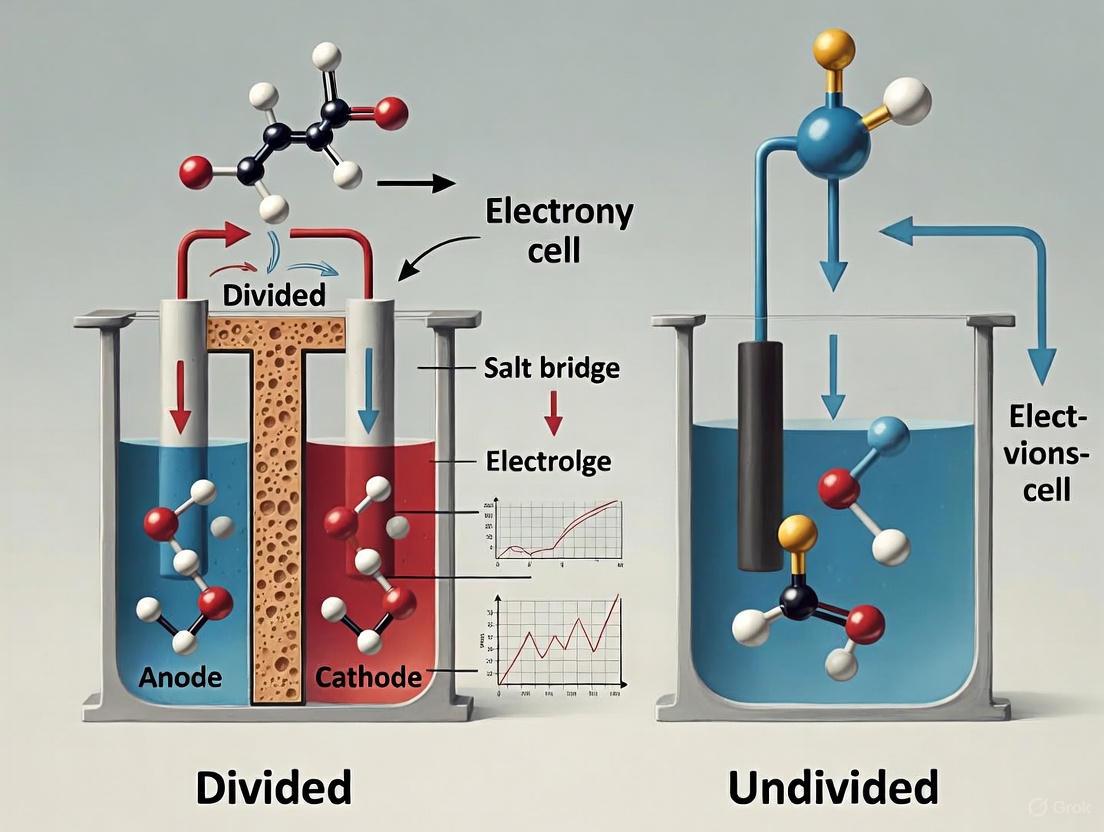
Cell Configurations: Divided vs. Undivided
A critical decision in experimental design is whether to use a divided or an undivided electrochemical cell. This choice primarily affects the selectivity of the reaction and the ease of product separation.
Undivided Cells
In an undivided cell, the anode and cathode are placed in the same compartment containing the electrolyte and substrates [8]. This setup is simpler and has lower electrical resistance.
Best suited for: Reactions where the intermediates or products formed at one electrode will not react further at the opposite electrode, or where such cross-reactions are not detrimental to the desired outcome [8] [1].
Divided Cells
A divided cell employs a physical barrier—such as a porous frit or an ion-selective membrane (e.g., Nafion)—to separate the anodic and cathodic compartments [8] [1]. This prevents the mixing of solutions and the chemical species within them.
Best suited for: Reactions where the product formed at the anode would be reduced at the cathode (or vice versa), leading to decreased yield or selectivity [1]. This configuration is crucial when the anodic and cathodic reactions are incompatible or when the independent collection of products from each electrode is desired [1]. A key advanced application is paired electrolysis, where both the anodic oxidation and cathodic reduction are productive, maximizing energy and atom economy [1].
Table 2: Comparison of Divided and Undivided Electrochemical Cell Configurations.
| Characteristic | Undivided Cell | Divided Cell |
|---|---|---|
| Compartmentalization | Single compartment for anode and cathode | Two physically separated compartments |
| Separator | None | Porous disk/frit or ion-exchange membrane |
| Complexity & Cost | Lower | Higher |
| Resistance | Lower | Higher (due to the membrane) |
| Selectivity | Can be lower due to cross-reactions | Higher, prevents interference between electrodes |
| Product Separation | More challenging; products from both reactions are mixed | Easier; anodic and cathodic products are separated |
| Ideal Use Cases | Simple reactions, large-scale processes where cost is a factor | Sensitive substrates, paired electrolysis, when product separation is difficult [1] |
Diagram 1: Decision workflow for selecting cell configuration and control mode.
The Scientist's Toolkit: Key Research Reagents & Materials
The following table details essential materials and their functions for setting up a general electrosynthesis experiment, adaptable for both divided and undivided cells.
Table 3: Essential Materials and Reagents for Electrochemical Synthesis.
| Item | Function/Purpose | Common Examples |
|---|---|---|
| Working Electrode | Surface where the desired redox reaction occurs; material choice dictates reaction pathway and efficiency. | Pt, Graphite, Boron-Doped Diamond (BDD), Glassy Carbon (GC) [8] [1] |
| Counter Electrode | Completes the circuit by undergoing the balancing half-reaction. | Pt wire/mesh, Ni, Ti grid [8] |
| Reference Electrode | Provides a stable reference potential for accurate control of the working electrode potential. | Ag/AgCl, Saturated Calomel Electrode (SCE) [8] [1] |
| Supporting Electrolyte | Dissociates into ions to provide conductivity in the solution; maintains charge balance. | Tetrabutylammonium salts (e.g., TBABF₄, TBAPF₆), Lithium perchlorate (LiClO₄) [1] |
| Solvent | Dissolves substrates and electrolytes; must be electrochemically inert in the operating potential window. | Acetonitrile (MeCN), Dimethylformamide (DMF), Dimethyl sulfoxide (DMSO) [1] |
| Membrane/Separator | (For divided cells) Allows ion transport while preventing mixing of anolyte and catholyte. | Nafion (PFSA), porous ceramic frits, SPEEK [1] |
Experimental Protocol: Basic Setup for an Electrosynthesis Reaction
This protocol provides a general methodology for setting up and running an electrosynthesis experiment, with specific notes for divided cell setups.
Materials and Equipment
- Instrumentation: Potentiostat/Galvanostat.
- Electrochemical Cell: Undivided or divided cell (e.g., H-cell or beaker-type).
- Electrodes: Appropriate WE, CE, and RE as per Table 3.
- Chemicals: Substrate, supporting electrolyte, and solvent (high purity).
Procedure
- Cell Assembly:
- For Undivided Cells: Place the working, counter, and reference electrodes into the single compartment.
- For Divided Cells: Assemble the cell with the membrane separator. Place the working and reference electrodes in one compartment (e.g., anolyte) and the counter electrode in the other (e.g., catholyte). Ensure the membrane is properly conditioned (e.g., soaked in solvent or water) as per manufacturer instructions.
- Solution Preparation: Dissolve the substrate and supporting electrolyte in the chosen solvent to create the electrolyte solution. For divided cells, add the solution to both compartments. If the reactions are different, the solutions in each compartment can be different.
- Instrument Connection: Connect the electrodes to the potentiostat/galvanostat—working (red), counter (white), and reference (green) leads to their respective electrodes.
- Parameter Setting (Galvanostatic Example for Synthesis):
- Select the galvanostatic mode.
- Set the constant current based on the electrode surface area or the desired reaction rate (e.g., 5-20 mA/cm²).
- Set the total charge to be passed (in Coulombs), calculated from the moles of substrate and the number of electrons transferred per molecule (Faraday's law).
- Reaction Execution: Start the experiment. Monitor the cell potential and temperature throughout the run.
- Work-up and Analysis: After the charge has been passed, stop the experiment. For divided cells, separately collect the solutions from the anodic and cathodic compartments. For undivided cells, the entire solution is worked up. Remove the electrolyte (e.g., by washing with water or filtration) and isolate the product using standard techniques (e.g., extraction, chromatography). Identify and quantify products using NMR, GC-MS, or HPLC.
Troubleshooting and Best Practices
- Low Current Flow: Check the conductivity of the electrolyte; ensure a sufficient concentration of supporting electrolyte is used. Verify all electrical connections are secure.
- Unstable Potential (in Galvanostatic Mode): This can indicate depletion of the reactant or fouling/passivation of the electrode surface.
- Poor Product Yield/Selectivity (in Undivided Cells): Consider switching to a divided cell to prevent cross-reactions between the primary products and the opposite electrode [1].
- General Recommendation: For initial exploratory experiments, a simple undivided cell under galvanostatic control is often the most straightforward setup. For reactions requiring high selectivity, a divided cell with potentiostatic control may be necessary to fine-tune the reaction conditions.
In synthetic organic chemistry and bioelectrocatalysis, electrochemical methods offer a versatile platform for achieving selective transformations by using electrons as clean reagents. The efficacy of these processes is fundamentally governed by the mechanism of electron transfer (ET) between the electrode and the substrate. Two primary paradigms exist: Direct Electron Transfer (DET), where the substrate interacts directly with the electrode surface, and Mediated Electron Transfer (MET), which utilizes a molecular shuttle to transport electrons [1]. The choice between these mechanisms profoundly influences the reaction's selectivity, efficiency, and feasibility, particularly within the broader strategic framework of using divided versus undivided electrochemical cells. Divided cells, which physically separate the anodic and cathodic chambers with a membrane, are especially advantageous for preventing cross-reactions between products generated at each electrode, thereby unlocking unique synthetic pathways and improving product isolation [1]. This application note delineates the core principles, comparative advantages, and practical protocols for DET and MET, providing researchers and development scientists with the tools to implement these techniques effectively.
Core Principles and Comparative Analysis
Fundamental Mechanisms
Direct Electron Transfer (DET) requires the reactant to adsorb directly onto the electrode surface, where it undergoes oxidation or reduction without an intermediary [1]. This heterogeneous process demands proximity and a compatible orientation for the electron to tunnel between the electrode and the redox center of the substrate. DET is often characterized by its simplicity but can be limited by slow kinetics, especially for substrates with redox centers embedded within large protein structures, such as enzymes [12].
In contrast, Mediated Electron Transfer (MET) employs a soluble redox-active species, known as a mediator or electron-transfer agent, that shuttles electrons from the electrode to the substrate in the solution bulk [1]. The mediator is first oxidized or reduced at the electrode surface, diffuses away, and then reacts chemically with the target substrate, regenerating its original state in the process. This mechanism can overcome limitations of slow heterogeneous kinetics and enables the transformation of substrates that cannot physically approach the electrode surface.
The schematic below illustrates the operational workflow and logical decision pathway for selecting and implementing these electron transfer mechanisms.
Comparative Analysis: DET vs. MET
The choice between DET and MET is strategic and depends on the specific requirements of the electrochemical process. Key operational characteristics and considerations for each mechanism are systematically compared in the table below.
Table 1: Comparative Analysis of Direct vs. Mediated Electron Transfer
| Feature | Direct Electron Transfer (DET) | Mediated Electron Transfer (MET) |
|---|---|---|
| Mechanism | Heterogeneous ET at electrode surface [1] | Homogeneous ET via a diffusing mediator [1] |
| Rate Kinetics | Can be limited by slow heterogeneous ET kinetics | Often faster; bypasses slow heterogeneous kinetics |
| Substrate Scope | Limited to electroactive species that can adsorb on the electrode | Broad; enables reaction of non-adsorbing or distant substrates [13] |
| Selectivity | Highly dependent on electrode material and potential | Tunable via mediator selection; can impart high chemoselectivity [14] |
| System Complexity | Simple (two-component: electrode & substrate) | More complex (three-component: electrode, mediator & substrate) |
| Key Applications | Bioelectrocatalysis with surface-active enzymes [12]; simple inorganic reactions | Organic synthesis (e.g., Ni-catalyzed cross-coupling) [14]; systems with slow ET kinetics |
Experimental Protocols
Protocol 1: Investigating DET of Sarcosine Oxidase on a Ti₃C₂Tₓ MXene Hybrid Interface
This protocol details the procedure for studying the direct electrochemistry and bioelectrocatalysis of the flavoenzyme Sarcosine Oxidase (SOx) on a screen-printed carbon electrode (SPCE) modified with a chitosan-MXene nanocomposite [12].
1. Electrode Modification and Immobilization
- Materials: Ti₃AlC₂ MAX phase, LiF, HCl, Chitosan (medium molecular mass), Acetic acid, Sarcosine Oxidase (SOx) from Bacillus sp., Phosphate Buffer (0.1 M, pH 7.0), Screen-Printed Carbon Electrodes (SPCEs), Ethanol.
- Synthesis of Ti₃C₂Tₓ MXene: Etch 1 g of Ti₃AlC₂ MAX phase by stirring in a mixture of 1 g LiF and 20 mL 9 M HCl for 24 hours at 35°C. Wash the resulting sediment repeatedly with deionized water via centrifugation until supernatant pH ≥6. Disperse the final delaminated Ti₃C₂Tₓ MXene powder in deionized water and sonicate to obtain a 3 mg mL⁻¹ colloidal suspension [12].
- Preparation of CS-MXene Nanocomposite: Mix the MXene suspension with a 0.1% chitosan solution (in 0.3% acetic acid) to achieve a final MXene concentration of 0.5 mg mL⁻¹. Shake this mixture overnight at 20°C and 1500 rpm.
- Enzyme Desalting: Desalt the commercial SOx enzyme stock solution using a Zeba Spin desalting column (7k MWCO) pre-equilibrated with 0.1 M PB (pH 7.4).
- Electrode Modification: Clean SPCEs with ethanol and dry under a nitrogen stream. Drop-cast 20 µL of the CS-MXene nanocomposite onto the SPCE working electrode surface and allow to dry. Subsequently, drop-cast 20 µL of the desalted SOx solution onto the modified SPCE and let it dry at room temperature in a laminar flow box. The final biosensor is designated as SPCE/CS-MXene/SOx [12].
2. Electrochemical Characterization of DET
- Apparatus: Standard three-electrode system with Ag/AgCl reference and Pt counter electrodes. Potentiostat/Galvanostat.
- Direct Electrochemistry: Record Cyclic Voltammograms (CV) of the SPCE/CS-MXene/SOx in a deaerated 0.1 M PB (pH 7.0) at scan rates from 0.1 to 1.0 V s⁻¹. Observe for a pair of well-defined, quasi-reversible redox peaks around -0.7 V (anodic) and -1.0 V (cathodic), corresponding to the FAD/FADH₂ cofactor of the enzyme [12].
- Data Analysis: Plot the peak currents (Ip) vs. scan rate (ν). A linear relationship confirms a surface-controlled, homogeneous DET process. Calculate the formal potential (E⁰') as the average of the anodic and cathodic peak potentials.
3. Direct Bioelectrocatalysis Assay
- Bioelectrocatalysis: Perform CV with the SPCE/CS-MXene/SOx in 0.1 M PB (pH 7.0) while successively adding aliquots of a sarcosine stock solution (e.g., 10-1000 µM).
- Analysis: Observe a significant increase in the cathodic current at approximately -0.66 V upon sarcosine addition, indicating direct bioelectrocatalysis where the enzyme oxidizes sarcosine and directly transfers electrons to the MXene-modified electrode [12].
Protocol 2: Mediated Electron Transfer for High-Current-Density Ni-Catalyzed Cross-Electrophile Coupling (eXEC)
This protocol describes the use of a cobaltocene mediator to achieve high current densities and selectivity in nickel-catalyzed cross-electrophile coupling, a transformation highly relevant to pharmaceutical development [14].
1. Reaction Setup in a Divided Cell
- Materials: NiBr₂(dtbbpy) complex (dtbbpy = 4,4'-di-tert-butyl-2,2'-bipyridine), Cobaltocene mediator (e.g., Bis(ethylcyclopentadienyl)cobalt(II), Co(CpEt)₂), Cobalt Phthalocyanine (CoPc), Aryl bromide and Alkyl bromide substrates, Dimethylformamide (DMF), Tetrabutylammonium tetrafluoroborate (NBu₄BF₄) electrolyte, Nafion 115 membrane.
- Cell Configuration: Use a divided H-cell equipped with a Nafion 115 membrane. Employ a Ni foam cathode (1 cm² geometric area) as the working electrode and an Fe rod sacrificial anode. The membrane prevents decomposition of the catalyst and mediator at the anode [14].
2. Standard Mediated eXEC Procedure
- Catholyte Preparation: In the cathodic chamber, combine the aryl bromide (0.5 mmol), alkyl bromide (0.75 mmol), NiBr₂(dtbbpy) (1 mol%), Co(CpEt)₂ (10 mol%), CoPc (2.5 mol%), and NBu₄BF₄ (0.10 M) in 10 mL of DMF.
- Anolyte Preparation: In the anodic chamber, add a solution of the supporting electrolyte in DMF.
- Electrolysis: Perform constant current electrolysis at 8 mA (8 mA/cm² based on Ni foam geometric area) until 2.1 F/mol of charge has been passed. Maintain the temperature at 25°C [14].
- Reaction Monitoring: Withdraw aliquots from the catholyte periodically for GC or HPLC analysis to monitor consumption of starting materials and formation of the cross-coupled product and potential side-products (e.g., biaryl from homocoupling, protodehalogenated arene).
3. Analysis and Optimization
- Yield and Selectivity: Determine the yield of the cross-coupled product and calculate the cross-selectivity as [Yield of Cross-Coupled Product] / [Yield of Homocoupled + Protodehalogenated Byproducts].
- Faradaic Efficiency (FE): Calculate FE as (moles of product formed × n × F) / (total charge passed) × 100%, where n is the number of electrons per molecule (typically 2) and F is the Faraday constant.
- Mediator Optimization: If the reaction performance is suboptimal, screen alternative cobaltocene mediators with redox potentials slightly above that of the Ni catalyst (e.g., -1.45 V vs Fc/Fc⁺) to ensure slightly endergonic electron transfer to the catalyst [14].
The Scientist's Toolkit: Key Research Reagent Solutions
Successful implementation of DET and MET methodologies requires a careful selection of specialized materials. The following table catalogues essential reagents and their functions.
Table 2: Essential Research Reagents for Electron Transfer Studies
| Reagent / Material | Function / Description | Application Context |
|---|---|---|
| Ti₃C₂Tₓ MXene | A 2D transition metal carbide with high conductivity and hydrophilic surface; promotes DET from enzyme cofactors [12]. | DET-based biosensors and bioelectrocatalysis. |
| Nafion 115 Membrane | A perfluorosulfonic acid-based cation-exchange membrane; serves as a physical separator in divided cells [1] [14]. | Divided cell setups for MET and DET to prevent cross-talk. |
| Chitosan | A natural biopolymer; acts as a hydrophilic "glue" for immobilizing enzymes on electrode surfaces while maintaining activity [12]. | Enzyme-based DET interfaces (e.g., SPCE/CS-MXene/SOx). |
| Cobaltocene Mediators (e.g., Co(CpEt)₂) | Homogeneous organometallic electron-transfer mediators with tunable redox potential [14]. | MET for Ni-catalyzed eXEC and other reductive transformations. |
| Cobalt Phthalocyanine (CoPc) | A redox cocatalyst; activates alkyl halide electrophiles in tandem with the main Ni-catalyst [14]. | MET systems for cross-electrophile coupling. |
| Sarcosine Oxidase (SOx) | A flavoenzyme containing a FAD cofactor; catalyzes the oxidation of sarcosine [12]. | Model enzyme for studying DET and direct bioelectrocatalysis. |
| dtbbpy-Ligated Ni Catalysts | Nickel complexes with a stabilizing bipyridyl ligand; central catalysts for cross-coupling [14]. | MET-based organic synthesis (e.g., eXEC). |
Visualization of MET-Enhanced Catalytic Cycle
The mechanistic pathway of a mediated electrocatalytic reaction, such as the Ni-catalyzed eXEC, involves a sophisticated interplay between the electrode, mediator, and catalyst. The following diagram delineates this catalytic cycle and the critical role of the electron-transfer mediator.
Within the broader research on divided versus undivided electrochemical cell setups, the control and measurement of three key operational parameters—Formal Redox Potential, Overpotential, and Faradaic Efficiency—are paramount. These parameters collectively determine the selectivity, energy efficiency, and scalability of electrosynthetic reactions, which are crucial for applications ranging from organic synthesis to drug development. Divided cells, which employ a physical separator to isolate the anodic and cathodic compartments, offer unique advantages for managing these parameters by preventing cross-talk between electrode reactions and enabling independent optimization of conditions at each electrode [1]. This application note provides a detailed framework for quantifying and applying these parameters, complete with structured data, experimental protocols, and essential toolkits for researchers.
Parameter Definitions and Core Principles
Formal Redox Potential (E⁰')
The Formal Redox Potential is the experimentally measured reduction potential for a redox couple under a specific set of conditions (pH, ionic strength, solvent), making it a practical value for predicting reaction feasibility [15]. It differs from the standard redox potential, which is defined for standard state conditions. In divided cells, the separation of anolyte and catholyte helps maintain a stable local environment, which is critical for obtaining reproducible and reliable formal potential measurements [1].
Overpotential (η)
Overpotential is the deviation of an electrode's potential from its thermodynamic equilibrium value required to drive a reaction at a specific current density [16] [17]. It represents the extra energy needed to overcome kinetic barriers and is a key determinant of voltage efficiency. The total overpotential (η_total) is the sum of contributions from activation, concentration, and resistance overpotentials [16]. In divided cell configurations, ohmic resistance overpotential can be significant due to the presence of a membrane, but this is often counterbalanced by gains in selectivity and current efficiency [1].
Faradaic Efficiency (FE)
Faradaic Efficiency is a measure of the effectiveness of charge transfer in producing a desired product [18] [19]. It is defined as the ratio of the charge used for the desired electrochemical transformation to the total charge passed through the cell. A high Faradaic Efficiency is critical for process economy and minimizing waste. Divided cells are particularly effective at achieving high Faradaic Efficiency for reactions where the product at one electrode is susceptible to further reaction at the opposite electrode, as the physical barrier prevents such cross-reactions [1].
Table 1: Key Operational Parameters and Their Characteristics
| Parameter | Definition & Units | Key Influencing Factors | Typical Target Values / Ranges (Context-Dependent) |
|---|---|---|---|
| Formal Redox Potential | Practical reduction potential under non-standard conditions (Volts, V) [15] [20]. | Solvent, electrolyte, temperature, ligand coordination, and local geometry of metal complexes [1] [15]. | Value specific to the redox couple; must be measured relative to a chosen reference electrode (e.g., SCE, Ag/AgCl) [1]. |
| Overpotential (η) | η = Eapplied - Eequilibrium (Volts, V) [16]. | Electrode material (see Table 2), electrolyte conductivity, membrane resistance, temperature, and current density [1] [16]. | Minimized for energy efficiency. Catalysts are selected for low η (e.g., Pt for HER: -0.09 V; Pt for OER: +1.11 V) [16]. |
| Faradaic Efficiency (FE) | FE = (Qdesired / Qtotal) × 100% [18] [19] or FE = (nactual / ntheoretical) × 100% [19]. | Electrode stability, competing side reactions, cell configuration (divided/undivided), and selectivity of the electrocatalyst [1] [18]. | Ideally 100%; >90% is often required for viable industrial processes. Divided cells help achieve high FE by preventing product crossover and degradation [1]. |
Table 2: Overpotential Values for Common Electrode Reactions on Different Materials (in Acidic Media) [16]
| Electrode Material | Hydrogen Evolution Reaction (HER) η (V) | Oxygen Evolution Reaction (OER) η (V) | Chlorine Evolution Reaction (CER) η (V) |
|---|---|---|---|
| Platinum (Pt) | -0.09 | +1.11 | +0.10 |
| Platinum (Platinized) | -0.01 | +0.46 | +0.08 |
| Nickel (Ni) | -0.32 | +0.61 | - |
| Iron (Fe) | -0.40 | +0.41 | - |
| Copper (Cu) | -0.50 | +0.58 | - |
| Graphite (C) | -0.47 | +0.50 | +0.12 |
| Mercury (Hg) | -1.04 | - | - |
Experimental Protocols
Protocol 1: Determining Formal Redox Potential via Cyclic Voltammetry
This protocol outlines the determination of the formal redox potential (E⁰') of a metal complex in aqueous solution using Cyclic Voltammetry (CV), applicable in both divided and undivided cell configurations for initial screening [15].
Workflow: Determination of Formal Redox Potential
Materials & Equipment:
- Potentiostat/Galvanostat
- Standard 3-electrode cell [15]
- Working Electrode: Glassy carbon, Platinum, or other inert material
- Counter Electrode: Platinum wire
- Reference Electrode: Saturated Calomel Electrode (SCE) or Ag/AgCl [1]
- Analyte: Solution containing the redox-active compound (e.g., 1 mM copper(II) complex) [15]
- Supporting Electrolyte: High-purity inert salt (e.g., 0.1 M KNO₃ or n-Bu₄NBF₄) to maintain conductivity and constant ionic strength [1] [15]
- Solvent: Deoxygenated high-purity water or appropriate organic solvent (e.g., MeCN, DMSO) [1]
Step-by-Step Procedure:
- Solution Preparation: Prepare a solution of the compound of interest (e.g., ~1 mM) in a suitable solvent with a supporting electrolyte (e.g., 0.1 M) [15]. Purge the solution with an inert gas (N₂ or Ar) for at least 10-15 minutes to remove dissolved oxygen.
- Cell Assembly: Set up the standard three-electrode cell. Ensure the working electrode is meticulously cleaned and polished according to standard protocols prior to immersion.
- CV Measurement: Record a cyclic voltammogram at a slow scan rate (e.g., 50-100 mV/s) over a suitable potential window where the redox event is observed. The scan should display both oxidation and reduction peaks.
- Data Analysis: Determine the formal redox potential (E⁰') from the CV as the average of the anodic (Epa) and cathodic (Epc) peak potentials: E⁰' = (Epa + Epc)/2 [15].
- Reporting: Report the measured E⁰' value with reference to the specific reference electrode used (e.g., E⁰' vs. Ag/AgCl) and detail all experimental conditions (solvent, electrolyte, temperature).
Protocol 2: Measuring Faradaic Efficiency in a Divided Cell
This protocol describes a bulk electrolysis experiment in a divided cell to determine the Faradaic Efficiency for a target product, which is essential for evaluating the practical utility of an electrochemical synthesis.
Workflow: Measurement of Faradaic Efficiency
Materials & Equipment:
- H-type Divided Cell equipped with an ion-exchange membrane (e.g., Nafion) or a porous separator [1]
- Power Supply: DC power source for galvanostatic electrolysis or a potentiostat [1]
- Electrodes: Appropriate working and counter electrodes (e.g., Pt, graphite, or modified electrodes)
- Coulometer or integrated charge counter in the potentiostat
- Analytical Instrumentation: Gas Chromatography (GC), High-Performance Liquid Chromatography (HPLC), or NMR for product quantification [18]
Step-by-Step Procedure:
- Cell Assembly: Assemble the H-cell, ensuring the membrane is properly conditioned. The two compartments are physically separated by the membrane, which allows ion transport but prevents mixing of anolyte and catholyte [1].
- Solution Preparation: Fill the anodic and cathodic compartments with their respective solutions, containing the substrates and supporting electrolytes. The use of divided cells allows for different solvents and electrolytes to be used in each chamber, which can be optimized independently [1].
- Bulk Electrolysis: Perform electrolysis under galvanostatic (constant current) conditions. Galvanostatic control is often preferred for scale-up as it does not require a reference electrode and uses simpler instrumentation [1]. Monitor and record the total charge passed (Q_total in Coulombs) throughout the experiment.
- Product Quantification: After passing a known charge, stop the electrolysis. Quantify the amount (moles, n_actual) of the target product formed using an appropriate analytical technique (e.g., GC, HPLC, NMR) [18].
- FE Calculation: Calculate the Faradaic Efficiency using the formula: FE (%) = (n_actual × F × z) / Q_total × 100% where F is the Faraday constant (96,485 C/mol), and z is the number of electrons required to produce one molecule of the product [18] [19].
The Scientist's Toolkit: Research Reagent Solutions
Table 3: Essential Materials for Electrochemical Synthesis in Divided Cells
| Item | Function/Application | Key Considerations |
|---|---|---|
| Ion-Exchange Membranes (e.g., Nafion) | Separates anodic and cathodic compartments while allowing selective ion transport to maintain charge balance [1]. | PFSA-based (e.g., Nafion): High proton conductivity, good chemical stability. Alternatives (SPEEK, SPAES): Lower cost, but may have lower durability. Choice depends on required conductivity and chemical resistance [1]. |
| Supporting Electrolytes (e.g., n-Bu₄NBF₄, LiClO₄) | Dissociates into ions in solution to provide necessary conductivity and reduce ohmic drop (resistance overpotential) [1]. | Must be inert (high redox stability window) and highly soluble. Tetraalkylammonium salts are common in organic electrochemistry. Can also act as stabilizing agents for intermediates [1]. |
| Reference Electrodes (e.g., SCE, Ag/AgCl) | Provides a stable, known reference potential against which the working electrode's potential is measured and controlled [1]. | Choice depends on solvent compatibility and potential window. A saturated calomel electrode (SCE) or Ag/AgCl is common for aqueous/organic solvents. Potential is often reported vs. a specific reference [1] [15]. |
| Electrode Materials (Pt, Graphite, BDD) | Surface where the electrochemical reaction occurs. Material choice critically influences reaction kinetics (overpotential) and selectivity [1] [16]. | Inert (Pt, Graphite, BDD): For direct electron transfer. Active/Metal Oxides: For mediated processes or specific catalysis (e.g., OER). Modified Electrodes: For enhanced selectivity (e.g., chiral modifications) [1] [16]. |
| Aprotic Solvents (MeCN, DMSO) | Dissolves organic substrates and supporting electrolytes. Their electrochemical stability is crucial to avoid solvent decomposition at high potentials [1]. | Must be polar enough to dissolve ionic salts. Common choices include acetonitrile (MeCN) and dimethyl sulfoxide (DMSO). Must be thoroughly dried for reactions sensitive to water [1]. |
Applied Strategies: Selecting Cell Setups for Synthesis and Degradation
Electrosynthesis has re-emerged as a vital tool for sustainable chemical production, replacing traditional redox reagents with electricity as a traceless reagent [1] [21]. Within this field, the choice between divided and undivided electrochemical cells represents a critical design consideration, particularly for synthesizing complex molecules where selectivity is paramount. Divided cells, which physically separate anodic and cathodic compartments using a semipermeable membrane, offer distinct advantages for controlling reaction pathways and preventing cross-reactions that often compromise product purity in undivided systems [1]. This application note provides detailed protocols and practical guidance for implementing divided cell electrosynthesis to achieve high selectivity in the synthesis of complex organic molecules, with specific relevance to pharmaceutical intermediates and other high-value compounds.
Fundamental Principles of Divided Cells
Core Concept and Configuration
Divided cells employ a physical barrier—typically a low-porosity ceramic frit or ion-conducting polymeric membrane—to separate the anode and cathode compartments while maintaining ionic conductivity [1]. This separation prevents the starting materials, intermediates, and products formed at one electrode from migrating to the opposite electrode and undergoing further undesirable redox reactions [1]. As illustrated in Figure 1, this configuration enables independent optimization of reactions at each electrode and facilitates efficient product separation [1].
Diagram: Divided Electrochemical Cell Configuration
Comparative Advantages Over Undivided Cells
Table 1: Divided vs. Undivided Cell Performance Characteristics
| Parameter | Divided Cell | Undivided Cell | Impact on Selectivity |
|---|---|---|---|
| Product Separation | Physical separation of anodic and cathodic products [1] | Potential mixing and cross-reactions [1] | Prevents decomposition and over-reaction of products |
| Current Efficiency | Higher due to minimized side reactions [1] | Lower due to competing redox events [1] | Improves yield and reduces purification complexity |
| Compatibility with Reactive Intermediates | Excellent for unstable or highly reactive species [1] | Limited due to exposure to both electrodes [1] | Enables transformations impossible in undivided systems |
| Independent Optimization | Anolyte and catholyte conditions can be optimized separately [1] | Single electrolyte must suit both half-reactions [1] | Allows pH, solvent, and electrolyte tuning for each reaction |
| Electrode Passivation | Reduced risk due to compartment separation [1] | Higher risk from reaction intermediates [1] | Improves reaction reproducibility and electrode lifetime |
Critical System Components and Selection Criteria
Membrane Technologies
The membrane represents the most critical component in divided cell systems, directly influencing cell performance, efficiency, and longevity [1]. Membrane selection must balance ionic conductivity, chemical stability, and cost considerations.
Table 2: Membrane Types for Divided Cell Electrosynthesis
| Membrane Type | Examples | Conductivity Range | Advantages | Limitations | Optimal Applications |
|---|---|---|---|---|---|
| Perfluorosulfonic Acid (PFSA) | Nafion [1] | 0.07-0.08 S/cm [1] | High proton conductivity, excellent chemical stability [1] | High cost, environmental concerns with fluorinated polymers [1] | Acidic media, proton-coupled electron transfers |
| Sulfonated Hydrocarbon | SPEEK, SPAES [1] | Comparable to Nafion (hydrated) [1] | Lower cost, reduced environmental impact [1] | Durability issues, water swelling [1] | Mild conditions, aqueous-organic mixed solvents |
| Hybrid/Composite | Silica-SPEEK, MOF-incorporated [1] | Enhanced vs. base materials [1] | Improved mechanical/thermal properties, boosted conductivity [1] | More complex fabrication, potential heterogeneity [1] | High-temperature applications, harsh chemical environments |
| Ceramic Diaphragms | Low-porosity ceramic frits [1] | Variable | Excellent chemical resistance, thermal stability [1] | Typically lower selectivity, potential for some crossover [1] | High-temperature electrolysis, molten salt systems |
Electrode Materials and Configurations
Electrode selection directly governs electron transfer mechanisms and reaction pathways. The choice between inert and active electrodes depends on whether direct or mediated electron transfer is desired.
Table 3: Electrode Materials for Selective Electrosynthesis
| Electrode Type | Common Materials | Electron Transfer Mechanism | Advantages | Ideal Reaction Types |
|---|---|---|---|---|
| Inert Electrodes | Platinum, Graphite, Boron-Doped Diamond [1] | Direct Electron Transfer (DET) [1] | Chemical stability, high current density tolerance [1] | Direct oxidation/reduction of organic substrates |
| Active Electrodes | Metal Oxides (Mn, Ni, Ir) [1] | Indirect via reactive intermediates [1] | Generation of reactive species (e.g., ROS), catalytic activity [1] | Selective oxygenation, degradation resistant compounds |
| Modified Surfaces | N-doped carbon, Polyaniline composites [1] | Enhanced DET or mediated pathways [1] | Improved selectivity through surface engineering [1] | Chiral synthesis, stereoselective transformations |
Solvent and Electrolyte Systems
Solvents and supporting electrolytes create the conductive medium necessary for electrolysis while influencing reaction pathways and selectivity.
Table 4: Solvent and Electrolyte Selection Guide
| Component | Examples | Key Properties | Considerations for Divided Cells |
|---|---|---|---|
| Solvents | MeCN, DMSO, DMF [1] | High polarity, aprotic nature [1] | Must dissolve ionic salts and organic substrates; stability at high potentials [1] |
| Supporting Electrolytes | n-Bu₄NBF₄, LiClO₄, Et₄NPF₆ [1] | High redox potential (electrochemical inertness) [1] | Maintains charge neutrality; critical for medium conductivity [1] |
| Dual-Function Electrolytes | Specific ionic liquids [1] | Active participation in reaction mechanism [1] | Can stabilize radical intermediates; enhances selectivity [1] |
Experimental Protocols
Standard Protocol for Divided Cell Electrosynthesis
Protocol 1: General Procedure for Selective Transformation Using a Divided Cell
Equipment and Materials:
- H-type divided glass cell or equivalent membrane-separated reactor
- Ion-exchange membrane (Nafion 117 or SPEEK for preliminary experiments)
- Electrodes: Graphite rods (2x) or Pt mesh (2x) (diameter: 5-10 mm)
- DC power supply or potentiostat/galvanostat
- Magnetic stirrer and stir bars (2x, one for each compartment)
- Argon or nitrogen gas supply for degassing
Reagent Preparation:
- Anolyte Preparation: Dissolve substrate (1.0 mmol) and supporting electrolyte (0.1 M n-Bu₄NBF₄) in dry, degassed solvent (20 mL, e.g., MeCN) in the anodic compartment.
- Catholyte Preparation: Dissolve supporting electrolyte (0.1 M n-Bu₄NBF₄) in the same solvent (20 mL) in the cathodic compartment. If a paired electrolysis is planned, add the second substrate (1.0 mmol) to the catholyte.
Cell Assembly:
- Place the membrane between the two cell compartments, ensuring a tight seal to prevent fluid leakage.
- Insert electrodes into their respective compartments, ensuring they are parallel and positioned approximately 1-2 cm from the membrane.
- Connect electrodes to the power supply, ensuring correct polarity (anode to positive, cathode to negative).
Electrolysis Procedure:
- Purge both compartments with inert gas (Ar or N₂) for 10-15 minutes to remove oxygen.
- Begin stirring both solutions at a moderate rate (300-500 rpm) to ensure efficient mass transport.
- Apply constant current (typical range: 5-20 mA/cm²) or constant potential (determined from prior cyclic voltammetry experiments).
- Monitor reaction progress by TLC, GC, or HPLC, tracking both substrate consumption and product formation.
- Continue electrolysis until complete substrate conversion or optimal yield is achieved (typically 2-8 hours, depending on substrate and current density).
- Terminate electrolysis by disconnecting the power supply.
Work-up and Product Isolation:
- Separately transfer anolyte and catholyte solutions to different containers.
- Remove solvent under reduced pressure.
- Separate products from supporting electrolyte by extraction (e.g., with ethyl acetate/water) or chromatography.
- Analyze products by NMR, MS, and other appropriate analytical methods.
Advanced Protocol: Paired Electrolysis for Enhanced Energy Efficiency
Protocol 2: Simultaneous Anodic and Cathodic Synthesis in a Divided Cell
Paired electrolysis utilizes both half-cell reactions productively, dramatically improving energy efficiency and process economics [1].
Special Considerations:
- Substrate Compatibility: Select anode and cathode reactions with matched charge requirements and compatible operational potentials.
- Membrane Selection: Choose membranes with appropriate ion selectivity (cation-exchange, anion-exchange, or bipolar) based on the ionic species needing transport.
- Current Balance: Ensure both half-reactions proceed at similar rates to prevent charge accumulation.
Experimental Modifications:
- Reaction Design: Incorporate productive transformations in both compartments, such as anodic oxidation of organics coupled with cathodic reduction of different substrates [1].
- Monitoring: Implement simultaneous reaction monitoring for both compartments (e.g., dual GC injection or online IR monitoring).
- Optimization: Independently optimize solvent, electrolyte, and electrode materials for each half-reaction to maximize overall yield and selectivity.
Analytical and Optimization Techniques
Protocol 3: Reaction Monitoring and Optimization Strategy
Cyclic Voltammetry for Parameter Determination:
- Perform CV of substrate (1-5 mM) in electrolyte solution using a standard three-electrode cell.
- Determine oxidation/reduction potentials versus appropriate reference electrode (Ag/AgCl, SCE).
- Assess electrochemical reversibility and identify potential side reactions.
Controlled Potential Electrolysis for Optimization:
- Use a potentiostat with three-electrode configuration (working, counter, reference) in a divided cell.
- Apply potential slightly beyond the redox wave identified by CV (typically +200-300 mV for oxidation, -200-300 mV for reduction).
- Monitor current decay over time, which indicates reaction progress.
Key Performance Metrics:
- Current Efficiency: (Moles product formed × n × F) / Total charge passed × 100%, where n = electrons per molecule, F = Faraday constant [1]
- Conversion: (1 - [Substrate]final/[Substrate]initial) × 100%
- Selectivity: (Moles desired product / Moles substrate consumed) × 100%
- Space-Time Yield: Mass of product / (Reactor volume × Time)
The Scientist's Toolkit: Essential Research Reagents and Materials
Table 5: Key Reagent Solutions for Divided Cell Electrosynthesis
| Category | Specific Examples | Function/Purpose | Application Notes |
|---|---|---|---|
| Membranes | Nafion 117, Nafion 115 [1] | Proton exchange, compartment separation [1] | Pretreatment required: boil in H₂O₂, H₂SO₄, then H₂O; standard for many oxidative transformations |
| Supporting Electrolytes | n-Bu₄NBF₄, n-Bu₄NPF₆ [1] | Provide ionic conductivity, maintain charge balance [1] | Concentration typically 0.05-0.1 M; ensure electrochemical stability in operating potential window |
| Solvents | Acetonitrile (MeCN), Dimethylformamide (DMF) [1] | Dissolve substrates and electrolytes, mediate electron transfer [1] | Must be anhydrous and oxygen-free for sensitive reactions; purity critical for reproducibility |
| Electrode Materials | Graphite rods/foils, Pt mesh, BDD [1] | Provide electron transfer interface [1] | Surface pretreatment (polishing, activation) essential for reproducible results |
| Mediators | Tempo, Quinones, Metal complexes [1] | Facilitate indirect electron transfer, lower overpotentials [1] | Enables transformations of poorly conducting substrates; enhances selectivity |
| Reference Electrodes | Ag/AgCl, SCE [1] | Provide stable potential reference in potentiostatic mode [1] | Essential for accurate potential control; requires proper isolation from reaction mixture |
Troubleshooting Common Challenges
Diagram: Experimental Workflow and Optimization Pathway
Table 6: Troubleshooting Common Issues in Divided Cell Electrosynthesis
| Problem | Potential Causes | Solutions | Preventive Measures |
|---|---|---|---|
| Low Current Efficiency | Competing solvent/electrolyte decomposition [1] | Adjust applied potential; optimize substrate concentration [1] | Perform comprehensive CV analysis prior to electrolysis |
| Membrane Fouling/Crossover | Precipitation of reaction products; incorrect membrane selection [1] | Implement pre-filtration; switch to alternative membrane type [1] | Test membrane compatibility with reaction mixture components |
| Product Decomposition | Over-electrolysis; exposure to opposite electrode [1] | Implement controlled potential electrolysis; optimize charge transfer [1] | Monitor reaction progress and terminate at optimal conversion |
| Gas Evolution | Water reduction/oxidation; electrolyte decomposition [1] | Ensure solvent/electrolyte dryness; adjust potential window [1] | Thoroughly dry solvents and use high-purity electrolytes |
| Poor Mass Transport | Inadequate stirring; viscous solutions [1] | Increase agitation; optimize electrode spacing [1] | Design cells with optimized geometry for enhanced mixing |
Divided cell electrosynthesis represents a powerful methodology for achieving high selectivity in the synthesis of complex organic molecules, particularly valuable in pharmaceutical development where precise control over reaction pathways is essential. The physical separation of anodic and cathodic processes enables transformations that would be impossible in conventional undivided cells, while paired electrolysis configurations offer enhanced energy efficiency. Successful implementation requires careful consideration of membrane properties, electrode materials, and operational parameters, but delivers unparalleled control over reaction selectivity. As electrochemical methods continue to gain prominence in sustainable synthesis, divided cell technologies will play an increasingly important role in enabling selective transformations of complex molecules for drug discovery and development.
This application note explores the use of undivided electrochemical cells for the synergistic degradation of organic contaminants. By leveraging simultaneous anodic oxidation and cathodic reduction in a single compartment, undivided cells offer a simplified, efficient, and cost-effective alternative to divided cell setups. This protocol details the underlying principles, provides a standardized experimental methodology, and presents quantitative data on performance metrics, serving as a practical guide for researchers in environmental remediation and drug development.
Electrochemical advanced oxidation processes (EAOPs) have emerged as powerful tools for the destructive treatment of recalcitrant organic contaminants in water. The choice of cell configuration—divided versus undivided—is fundamental to the process design, impacting cost, complexity, and reaction mechanisms.
In a divided cell, a physical separator (e.g., an ion-exchange membrane or ceramic frit) prevents the mixing of anolyte and catholyte [1]. This separation is crucial when the products of one electrode could react at the opposite electrode or when incompatible reaction conditions are required in each compartment [1]. However, the membrane increases system resistance, requires a more complex setup, and can lead to higher operational costs.
Conversely, an undivided cell operates with both electrodes in a single shared electrolyte solution. This configuration is inherently simpler, offers lower ohmic resistance (which can reduce energy consumption), and is easier to construct and operate [22]. The absence of a membrane eliminates concerns regarding membrane fouling or degradation. Crucially for contaminant degradation, the undivided cell allows for synergistic reactions where species generated at one electrode can immediately interact with species from the counter electrode, leading to enhanced degradation pathways [22]. For instance, anodically generated reactive oxygen species (ROS) like hydroxyl radicals (•OH) can work in concert with cathodically generated hydrogen peroxide (H₂O₂) to create a highly oxidative environment.
The following diagram illustrates the core components and processes within a typical undivided electrochemical cell.
Table 1: Comparative Analysis of Divided vs. Undivided Electrochemical Cells
| Feature | Divided Cell | Undivided Cell |
|---|---|---|
| Cell Configuration | Two compartments separated by a membrane [1] | Single compartment with both electrodes [22] |
| Key Advantage | Prevents cross-reaction of species; independent control of anolyte/catholyte [1] | Simpler setup; lower resistance; enables synergistic redox reactions [22] |
| Complexity & Cost | Higher (membrane cost, complex assembly) [1] | Lower (no membrane, simpler design) [22] |
| Ohmic Resistance | Higher (due to membrane) [1] | Lower [22] |
| Ideal Application | Reactions where products at one electrode would react at the other [1] | Contaminant degradation where synergistic oxidation/reduction is beneficial [22] |
Materials and Reagent Solutions
Table 2: Essential Research Reagents and Materials
| Item | Function/Description | Common Examples & Notes |
|---|---|---|
| Working Electrode (Anode) | Site of oxidation; generates reactive oxygen species (ROS) and directly oxidizes contaminants. | Borono-Doped Diamond (BDD): High O₂ overpotential, yields abundant •OH [1].Mixed Metal Oxide (MMO): Cost-effective for chlorine evolution.Platinum (Pt): Good conductivity but can be expensive [22]. |
| Counter Electrode (Cathode) | Site of reduction; completes the electrical circuit and can generate reductants like H₂O₂. | Carbonaceous (Graphite, CF): Favors H₂O₂ production from O₂ reduction [22].Stainless Steel: Durable and low-cost.Sacrificial Anode: (e.g., Fe, Al) dissolves to provide coagulant ions (e.g., Fe²⁺) for Fenton reactions [22]. |
| Supporting Electrolyte | Increases solution conductivity; minimizes ohmic losses and energy consumption. | Sodium Sulfate (Na₂SO₄): Inert, suitable for •OH-mediated reactions [22].Sodium Chloride (NaCl): Generates active chlorine oxidants.Buffer Salts: Control pH for optimal reaction pathways. |
| Solvent | Dissolves contaminants, electrolyte, and facilitates charge transfer. | Water: Primary solvent. Adjust pH with H₂SO₄ or NaOH as needed. Organic co-solvents (e.g., acetonitrile) are less common for aqueous treatment [1]. |
| Target Contaminant | Model pollutant for degradation studies. | Pharmaceuticals: Carbamazepine, Diclofenac.Industrial Chemicals: Phenol, pesticides.Prepare a stock solution for spiking. |
Experimental Protocol: Contaminant Degradation in an Undivided Cell
Apparatus Setup and Assembly
This protocol outlines a generalized procedure for evaluating contaminant degradation using a batch undivided cell under galvanostatic (constant current) conditions, which is simpler to implement than potentiostatic control and is common for preparative-scale reactions [22].
Step 1: Cell Preparation. Clean the chosen electrochemical cell (e.g., a 250-500 mL beaker) and all electrodes with appropriate solvents (e.g., dilute acid, followed by rinsing with deionized water) to remove any organic or inorganic residues.
Step 2: Electrolyte and Contaminant Preparation. Prepare the reaction solution by dissolving the selected supporting electrolyte (e.g., 0.05 M Na₂SO₄) in deionized water. Spike this solution with the target contaminant from a concentrated stock solution to achieve the desired initial concentration (e.g., 10-50 mg/L).
Step 3: Electrode Immersion and Configuration. Immerse the anode and cathode into the solution, ensuring a consistent and known inter-electrode distance (e.g., 1-2 cm). The electrode connection to the DC power supply should be secure. If using a magnetic stirrer, place a stir bar in the solution to ensure hom mixing.
Step 4: System Check. Prior to applying current, verify that all electrical connections are correct and the power supply is set to zero. Begin stirring the solution at a constant rate.
Operational Procedure and Data Collection
Step 1: Reaction Initiation. Turn on the DC power supply and set it to galvanostatic mode. Apply a constant current density relevant to the electrode materials and cell design. A typical range for many studies is 10-50 mA/cm² [1]. Record the initial cell voltage.
Step 2: Reaction Monitoring. Let the reaction proceed for a predetermined duration (e.g., 30-120 minutes). At regular time intervals (e.g., t = 0, 15, 30, 60, 90, 120 min), withdraw small aliquots (e.g., 2-5 mL) from the cell for analysis.
Step 3: Sample Quenching and Analysis. Immediately quench any residual oxidants/reductants in the sample aliquot, if necessary (e.g., with sodium thiosulfate). Analyze the samples for:
- Contaminant Concentration: Via High-Performance Liquid Chromatography (HPLC).
- Total Organic Carbon (TOC): To evaluate mineralization efficiency.
- pH and Byproduct Identification: As required.
Step 4: Reaction Termination. After the final sample is collected, turn off the power supply and then the stirrer.
The workflow below summarizes this experimental procedure.
Key Performance Metrics and Data Analysis
The efficiency of the electrochemical process is evaluated using several key metrics, calculated from the experimental data.
Table 3: Key Performance Metrics for Electrochemical Degradation
| Metric | Formula | Unit | Interpretation |
|---|---|---|---|
| Contaminant Removal Efficiency | ( (C0 - Ct)/C_0 \times 100\% ) | % | Measures the disappearance of the parent compound. |
| Mineralization Efficiency (TOC Removal) | ( (TOC0 - TOCt)/TOC_0 \times 100\% ) | % | Measures the conversion of organic carbon to CO₂. |
| Specific Energy Consumption (EC) | ( (E_{cell} \cdot I \cdot t)/V ) | kWh/m³ | Energy required to treat a unit volume; lower is better. |
| Average Current Efficiency (ACE) | ( ( (TOC0 - TOCt) \cdot F \cdot V )/(4 \cdot I \cdot t \cdot 3600) ) * | % | Efficiency of current use for mineralization. |
Where: ( C_0, TOC_0 ): initial concentration/TOC; ( C_t, TOC_t ): concentration/TOC at time *t; ( E_{cell} ): average cell voltage (V); I: current (A); t: electrolysis time (s or h); V: solution volume (L or m³); F: Faraday constant (96485 C/mol). * Formula assumes complete mineralization to CO₂.*
Anticipated Results and Data Presentation
Using the protocol above, a typical experiment with a BDD anode and a carbon-felt cathode in Na₂SO₄ electrolyte should demonstrate rapid degradation of a model pharmaceutical like carbamazepine. The data can be effectively summarized in the following tables.
Table 4: Simulated Degradation Data for Carbamazepine (Initial Conc.: 20 mg/L)
| Time (min) | Carbamazepine Conc. (mg/L) | Removal Efficiency (%) | TOC (mg/L) | Mineralization (%) | pH |
|---|---|---|---|---|---|
| 0 | 20.0 | 0.0 | 12.5 | 0.0 | 6.5 |
| 15 | 8.5 | 57.5 | 11.1 | 11.2 | 6.3 |
| 30 | 2.1 | 89.5 | 9.2 | 26.4 | 6.1 |
| 60 | 0.3 | 98.5 | 6.5 | 48.0 | 5.8 |
| 120 | <0.1 | >99.5 | 3.8 | 69.6 | 5.5 |
Table 5: Calculated Process Efficiency Metrics (for t=60 min)
| Metric | Value | Conditions |
|---|---|---|
| Specific Energy Consumption | 0.45 kWh/m³ | I = 0.5 A, E_cell = 4.5 V, V = 0.3 L |
| Average Current Efficiency | 32.5 % | Calculated from TOC removal |
Troubleshooting and Optimization Guide
- Low Degradation Rate: Check electrode connections and surface area. Verify electrolyte concentration to ensure sufficient conductivity. Consider increasing the applied current density within stable operating limits.
- Rapid Electrode Fouling/Passivation: The electrode surface may be coated with polymeric byproducts. Periodic polarity reversal or using a BDD anode with high corrosion resistance can mitigate this [1].
- High Cell Voltage: This indicates high system resistance. Ensure inter-electrode distance is minimized and electrolyte concentration is adequate. Stirring should be sufficient to remove gas bubbles from electrode surfaces.
- Poor Mineralization vs. Degradation: If the parent compound disappears but TOC remains high, the process is generating transformation products rather than complete oxidation. Optimization may require adjusting pH, using a more powerful anode like BDD, or adding a catalyst to promote Fenton reactions if Fe²⁺ is present.
Paired electrolysis represents an advanced electrochemical strategy that moves beyond conventional processes by enabling valuable product formation at both the anode and cathode simultaneously. This approach maximizes atomic and energy efficiency, offering a more sustainable and economically viable pathway for chemical synthesis powered by renewable electricity [23] [24]. Unlike traditional electrolysis that employs sacrificial reactions at one electrode, paired electrolysis leverages coordinated redox processes, turning the counter electrode reaction from a wasteful process into a productive one [25].
Framed within the broader research context of divided versus undivided cell setups, successful paired electrolysis implementation critically depends on the careful selection of cell configuration. Divided cells, separated by ionic conduction membranes, prevent cross-talk and degradation of products between electrodes, which is crucial when anodic and cathodic products are incompatible [1]. Conversely, undivided cells offer simpler design and lower cost but require carefully matched reaction conditions. The choice between these configurations fundamentally influences mass transport, interfacial challenges, process integration, and ultimately, the techno-economic feasibility of scaling paired reactions from laboratory demonstrations to industrial applications [23] [26].
Principles and System Configurations
Defining Paired Electrolysis and its Advantages
In a typical electrochemical cell, electrical energy drives chemical transformations via two half-reactions: oxidation at the anode and reduction at the cathode. In standard electrolysis, only one of these reactions produces a desired product, while the other is often a sacrificial process, such as oxygen evolution (OER) or hydrogen evolution (HER), which consumes significant energy while generating low-value products [23]. Paired electrolysis fundamentally changes this paradigm by coupling two valuable half-reactions in a single cell or coordinated system.
This strategy offers multiple key advantages:
- Maximized Energy Efficiency: Electrical current is utilized productively at both electrodes, dramatically improving the process's overall electron economy and reducing energy consumption per unit of product [23] [24].
- Enhanced Process Economics: The co-production of two valuable chemicals from a single electrical energy input can improve cost-effectiveness and return on investment [25].
- Reduced Environmental Impact: By avoiding sacrificial reagents and leveraging renewable electricity, paired electrolysis supports the transition to greener, more sustainable chemical manufacturing [1].
Divided vs. Undivided Cell Setups
The physical configuration of the electrochemical cell is a primary consideration in designing a paired electrolysis process, with the divided cell being a cornerstone technology for many applications.
Divided Cells utilize a physical barrier, typically a semipermeable membrane or a porous frit, to separate the anodic and cathodic compartments [1]. This barrier allows the passage of ions to maintain charge balance but prevents the mixing of solution-phase reactants and products between compartments.
- Primary Advantage: Prevention of cross-talk and undesirable side reactions. This is critical when the product of one electrode reaction could be consumed or degraded at the opposite electrode, or when reaction conditions (e.g., pH, solvent) differ significantly between half-reactions [1].
- Common Membranes: Industrial systems often use perfluorosulfonic acid (PFSA) membranes like Nafion for their high proton conductivity and chemical stability. Alternatives include sulfonated poly(ether-ether-ketone) (SPEEK) and sulfonated poly(aryl ether sulfone) (SPAES), which offer lower cost [1].
Undivided Cells lack a physical barrier between the electrodes, creating a single reaction chamber.
- Primary Advantage: Simpler reactor design, lower capital and maintenance costs (no membrane replacement), and reduced system resistance [1].
- Key Challenge: Requires that all reactants, intermediates, and products, as well as the reaction conditions (electrolyte, pH, solvent), be compatible with both half-reactions without interference [1].
A innovative approach that transcends this traditional dichotomy is Modular Electrochemical Synthesis (ModES). This method uses a redox reservoir (RR), a solid-state battery material such as nickel hexacyanoferrate (NiHCF), to temporarily store and release ions and electrons [25]. The half-reactions are run sequentially in separate cells—which can be divided or undivided—each paired with the RR. This enables the pairing of reactions with incompatible conditions, such as an organic oxidation in methanol with an aqueous reduction, overcoming one of the most significant limitations of conventional paired electrolysis [25].
Visualizing System Architectures
The diagram below illustrates the core configurations for implementing paired electrolysis, highlighting the flow of electrons and ions in each setup.
Quantitative Performance and Benchmarking
Transitioning paired electrolysis from laboratory discovery to industrial application requires meeting stringent performance benchmarks. The following table summarizes key performance indicators (KPIs) and reported data for selected paired electrolysis systems, highlighting the influence of cell configuration.
Table 1: Performance Benchmarks for Paired Electrolysis Systems
| Paired Reaction System | Cell Type | Current Density | Faradaic Efficiency (Anode/Cathode) | Key Performance Highlights | Primary Challenges |
|---|---|---|---|---|---|
| Biomass Upgrade + H₂(e.g., HMF to FDCA) [23] [24] | Undivided or Divided | > 200 mA/cm² (Industrial Target) | >90% (Anode) / >90% (Cathode) | Performance several times greater than standard HER/OER systems; significantly lower energy requirement [24]. | Matching reaction kinetics; product separation in undivided cell. |
| Plastic Upcycling + H₂(e.g., PET to formate) [23] | Varied | Industrial-level current densities achieved [23] | 93.2% (Anode, formate) [23] | Co-production of high-value chemicals and clean hydrogen from waste streams. | Complex feedstock impurities; reactor fouling. |
| ModES: Organic Synthesis + H₂O₂ Production(e.g., toluene oxidation + O₂ reduction) [25] | Dual Undivided Cells with RR | Laboratory Scale | High conversion & H₂O₂ production [25] | Pairs incompatible aqueous and non-aqueous reactions; eliminates membrane; enables different reaction scales/time [25]. | RR cycling stability and capacity; process complexity. |
| Propylene Oxidation (paired with HER or ORR) [23] [26] | Divided | High (Case Study) | Benchmarking against thermocatalytic routes [23] [26] | Improved process economics compared to sacrificial anodes; milder operating conditions. | Integration with existing industrial infrastructure. |
The data demonstrates that high current densities, essential for industrial economics, are achievable. Furthermore, high Faradaic efficiency for both half-reactions is critical for maximizing the energy efficiency benefit that is the hallmark of paired electrolysis [23] [24]. The techno-economic viability of any paired process must be rigorously benchmarked against state-of-the-art thermocatalytic or conventional electrochemical processes to justify further development [23] [26].
Detailed Experimental Protocols
Protocol 1: Paired Electrosynthesis in a Standard Divided H-Cell
This protocol outlines a general procedure for conducting a paired electrolysis reaction in a laboratory-scale divided H-cell, a common setup for initial feasibility studies [1].
4.1.1 Research Reagent Solutions and Materials
Table 2: Essential Materials for Divided Cell Electrosynthesis
| Item | Specification/Function |
|---|---|
| Electrochemical H-Cell | Glass cell with two compartments separated by a membrane. |
| Membrane | Nafion 117 (or similar PFSA membrane): Allows proton transport while preventing mixing of anolyte/catholyte. Pre-treatment (e.g., boiling in H₂O₂, H₂SO₄, and DI water) is required [1]. |
| Electrodes | Working Electrode (Anode): Pt mesh, graphite foil, or metal oxide (e.g., NiCo₂O₄) for oxidation.Counter Electrode (Cathode): Pt mesh, carbon felt, or Cu foil for reduction.Reference Electrode: Ag/AgCl (in aqueous systems) or SCE. Placed in the working electrode compartment. |
| Potentiostat/Galvanostat | Instrument for controlling cell potential or current. |
| Anolyte Solution | Substrate for oxidation (e.g., 50 mM HMF) dissolved in suitable solvent (e.g., water, MeCN) with supporting electrolyte (e.g., 0.1 M KOH for base, 0.1 M KCl for neutral). |
| Catholyte Solution | Substrate for reduction (e.g., proton source for H₂, or CO₂ for reduction) dissolved in solvent with supporting electrolyte. Electrolyte ion type (e.g., K⁺, H⁺) should match membrane conductivity. |
| Gas Inlet/Outlet | For purging (e.g., N₂ for inert atmosphere, CO₂ for CO₂ reduction) and collecting gaseous products (e.g., H₂). |
4.1.2 Step-by-Step Procedure
- Membrane Preparation: Activate the Nafion membrane by sequentially boiling in 3% H₂O₂, deionized water, 0.5 M H₂SO₄, and finally deionized water again, for 1 hour each. Store in deionized water until use [1].
- Electrolyte Preparation: In two separate beakers, prepare the anolyte and catholyte solutions. Dissolve the precise concentrations of the substrate and supporting electrolyte in the chosen solvent. Degas the solutions by sparging with an inert gas (e.g., N₂ or Ar) for 20-30 minutes to remove dissolved oxygen.
- Cell Assembly: Assemble the dry H-cell. Insert the pre-treated, moist membrane between the two compartments and clamp tightly to ensure a good seal. Insert the anode into the anolyte compartment and the cathode into the catholyte compartment. Carefully position the reference electrode in the working electrode compartment (typically the anode for an oxidation-paired reaction).
- Solution Transfer & Purging: Pour the degassed anolyte and catholyte into their respective compartments. Continue to purge the headspace of each compartment with inert gas or the required reactive gas (e.g., CO₂).
- Electrical Connection: Connect the working, counter, and reference electrodes to the corresponding leads of the potentiostat.
- Electrolysis Execution: Initiate the electrolysis under galvanostatic (constant current) or potentiostatic (constant potential) control. Galvanostatic operation is more common for scale-up as it uses simpler power supplies [1]. Monitor the total charge passed (in Coulombs).
- Process Monitoring: Periodically take small samples from each compartment for analysis (e.g., HPLC, GC) to monitor conversion, selectivity, and Faradaic efficiency.
- Reaction Termination & Work-up: Once the desired charge has been passed or conversion is achieved, stop the electrolysis. Disconnect the power and disassemble the cell.
- Product Isolation: Work up the anolyte and catholyte solutions separately. Techniques may include extraction, evaporation, filtration, or crystallization to isolate the products from each compartment. Analyze the final products to determine yield and purity.
Protocol 2: Modular Paired Electrolysis via a Redox Reservoir
This protocol describes the sequential pairing of two half-reactions across different solvents using a NiHCF redox reservoir, based on the ModES strategy [25].
4.2.1 Research Reagent Solutions and Materials
- Redox Reservoir (RR) Electrode: NiHCF (Nickel Hexacyanoferrate) coated on a conductive substrate (e.g., carbon felt or graphite). Synthesized via co-precipitation [25].
- Two Undivided Electrochemical Cells: One configured for the anodic step, one for the cathodic step.
- Anodic Reaction Solution: e.g., 4-tert-butyltoluene (methylarene) in methanol with supporting electrolyte (e.g., LiClO₄).
- Cathodic Reaction Solution: e.g., Oxygen-saturated aqueous solution with supporting electrolyte (e.g., K₂SO₄).
- Potentiostat/Galvanostat.
4.2.2 Step-by-Step Procedure
- RR Pre-conditioning: Place the NiHCF RR electrode in a clean cell. Electrochemically oxidize the RR electrode by applying a suitable anodic potential in an inert electrolyte to ensure it is in the state ready for reduction.
- Anodic Half-Reaction: a. Transfer the RR electrode to the anodic reaction cell containing the organic substrate in methanol. b. Perform electrolysis with the RR as the cathode (undergoing reduction with H⁺ intercalation) and a suitable inert anode (e.g., Pt). The organic substrate is oxidized at the anode. c. Continue until the desired charge is passed or the RR is sufficiently reduced. Monitor the conversion of the organic substrate. d. Remove the RR electrode, rinse gently with solvent, and dry.
- Cathodic Half-Reaction: a. Transfer the same, now reduced, RR electrode to the cathodic reaction cell containing the O₂-saturated aqueous solution. b. Perform electrolysis with the RR as the anode (undergoing oxidation with H⁺ release) and a suitable cathode (e.g., carbon felt for O₂ reduction). H₂O₂ is produced at the cathode. c. The H⁺ released from the RR neutralizes the OH⁻ generated at the cathode during H₂O₂ production, maintaining pH balance. d. Continue until the RR is fully re-oxidized.
- Cycle Repetition: The RR electrode can be shuttled back and forth between the two reaction cells for multiple cycles, enabling continuous co-production of the two valuable chemicals in separate, optimized environments [25].
The Scientist's Toolkit: Essential Research Reagents and Materials
Successful implementation of paired electrolysis, whether in standard divided cells or using advanced ModES, relies on a core set of materials and reagents.
Table 3: Key Research Reagent Solutions and Materials for Paired Electrolysis
| Category | Item | Typical Examples & Specifications | Critical Function |
|---|---|---|---|
| Cell Components | Membrane (Divided Cell) | Nafion 117/115 (PFSA): High proton conductivity. SPEEK/SPAES: Lower-cost hydrocarbon alternatives. Ceramic frits: Low-porosity separators. | Ionic conduction; physical separation of anolyte/catholyte to prevent cross-talk and product degradation [1]. |
| Electrodes | Anodes: Pt, Boron-Doped Diamond (BDD), NiOₓ, CoOₓ. Cathodes: Pt, Cu, Carbon felt, Pb. Single-Atom Catalysts (SACs): e.g., Ni-SA, Fe-SA on N-doped carbon. | Provide active sites for the specific half-reactions; critical for achieving high current density, low overpotential, and high product selectivity [23] [24]. | |
| Chemical Reagents | Solvents | Aqueous: Water (KOH or H₂SO₄ electrolyte). Non-aqueous: Acetonitrile (MeCN), Dimethyl Sulfoxide (DMSO), Methanol (MeOH). | Dissolve substrates and electrolytes; their polarity, nucleophilicity, and electrochemical stability window must be compatible with both half-reactions [1]. |
| Supporting Electrolytes | For organic solvents: Tetraalkylammonium salts (e.g., "n-Bu₄NBF₄"). For water: Alkali metal salts (e.g., K₂SO₄) or acids/bases (H₂SO₄, KOH). | Provide ionic conductivity; maintain charge neutrality. Dual-function electrolytes can also stabilize reactive intermediates [1]. | |
| Substrates & Feedstocks | Anodic: Biomass (HMF), plastics (PET), organic substrates. Cathodic: CO₂, H₂O (for H₂), O₂ (for H₂O₂), nitrogen species. | Raw materials for transformation into value-added products. Purity and concentration affect mass transport and reaction rates. | |
| Advanced Materials | Redox Reservoir (ModES) | Prussian Blue Analogues (PBAs): e.g., Nickel Hexacyanoferrate (NiHCF). Must be stable in relevant solvents and have suitable redox potential [25]. | Enables spatio-temporal decoupling of half-reactions; acts as a mediator for ion/electron storage and release, allowing pairing of incompatible reactions [25]. |
Paired electrolysis represents a paradigm shift towards more efficient and sustainable electrified chemical synthesis. The strategic utilization of reactions at both electrodes maximizes the value derived from electrical energy input. The choice between divided and undivided cell configurations is fundamental, presenting a trade-off between the operational simplicity and the necessity to prevent cross-reactions. Emerging strategies, such as ModES with redox reservoirs, offer unprecedented flexibility to overcome the traditional limitations of reaction compatibility. For researchers in drug development and fine chemicals, these advanced paired and modular approaches open new avenues for conducting selective transformations under mild conditions, potentially streamlining synthetic routes to complex molecules. As catalyst design, reactor engineering, and process integration continue to advance, paired electrolysis is poised to move from a promising laboratory technique to a cornerstone of green chemical manufacturing.
The strategic application of electrohydrodimerization (EHD) in mixed-substrate systems represents an emerging frontier in sustainable pharmaceutical intermediate synthesis. This approach leverages paired electrolysis to concurrently drive valuable transformations at both the anode and cathode, maximizing atom and electron economy while minimizing energy consumption and waste generation [27]. Within the broader research context of divided versus undivided electrochemical cell setups, divided cells provide the essential physical separation to prevent cross-reactions between anodically and cathodically generated intermediates, enabling complex reaction schemes that would be unfeasible in standard undivided systems [1]. This application note details a protocol for a model paired electrolysis system coupling the cathodic electrohydrodimerization of acrylonitrile (AN) to adiponitrile (ADN) with the anodic oxidation of 5-hydroxymethylfurfural (HMF) to 2,5-furandicarboxylic acid (FDCA), demonstrating the operational advantages and synthetic versatility of divided cell configurations for pharmaceutical manufacturing [27].
Background and Principles
Electrohydrodimerization (EHD) Fundamentals
Electrohydrodimerization is an electrosynthetic process wherein two molecules of an activated alkene, such as acrylonitrile, undergo reductive coupling at a cathode surface to form a dimeric product [28]. The classical EHD of acrylonitrile to adiponitrile (a nylon-66 precursor) is one of the few industrially scaled organic electrosyntheses, with annual production exceeding one million tons [27]. The reaction proceeds through a mechanism where the activated alkene accepts an electron at the cathode to form a radical anion intermediate, which then couples with a second molecule to form the dimer [28]. In divided cell systems, this cathodic process can be strategically paired with a value-added anodic oxidation, replacing the energy-intensive oxygen evolution reaction (OER) that typically occurs at the anode [27].
Divided vs. Undivided Cell Configurations
The choice between divided and undivided electrochemical cell setups profoundly impacts reaction efficiency, selectivity, and practicality for mixed-substrate systems:
Table 1: Comparison of Divided and Undivided Cell Configurations for Mixed-Substrate Electrolysis
| Parameter | Divided Cell | Undivided Cell |
|---|---|---|
| Product Separation | Simplified; products physically isolated in separate compartments [1] | Complex; requires additional separation steps |
| Cross-Reactions | Prevented by membrane/separator [1] | Likely; can lead to decreased selectivity |
| Substrate Compatibility | Ideal for incompatible anolyte/catholyte systems [1] | Limited to compatible electrolyte mixtures |
| Cell Design & Operation | More complex; requires membrane and separate chambers [1] | Simpler; single-compartment design |
| Optimization Flexibility | Independent optimization of anodic and cathodic conditions possible [1] | Conditions must suit both half-reactions simultaneously |
| Ohmic Losses | Higher due to membrane resistance [1] | Lower; no membrane resistance |
For mixed-substrate systems targeting high-value pharmaceutical intermediates, divided cells offer decisive advantages by preventing undesirable cross-reactions between anodically and cathodically generated species, enabling independent optimization of both half-cell environments, and facilitating product isolation [1].
Protocol: Paired Electrolysis of Acrylonitrile and 5-Hydroxymethylfuran
Principle and Reaction Scheme
This protocol describes a paired electrolysis system that couples the cathodic electrohydrodimerization of acrylonitrile (AN) to adiponitrile (ADN) with the anodic oxidation of biomass-derived 5-hydroxymethylfurfural (HMF) to 2,5-furandicarboxylic acid (FDCA), a promising renewable polymer precursor [27]. Replacing the conventional anodic oxygen evolution reaction (OER; E° = 1.23 V) with HMF oxidation (E° = 0.3 V) significantly reduces the energy requirement by approximately 0.93 V, dramatically improving the process's overall energy efficiency and economic viability [27]. The paired reactions are as follows:
- Cathode (Reduction): 2 CH₂=CH-CN + 2 e⁻ + 2 H⁺ → NC-(CH₂)₄-CN (Adiponitrile, ADN)
- Anode (Oxidation): HOC₆H₄OCH₂OH (HMF) + 2 H₂O → HOC₆H₄OCOOH (FDCA) + 6 H⁺ + 6 e⁻
Equipment and Materials
The Scientist's Toolkit: Research Reagent Solutions
Table 2: Essential Materials and Reagents
| Item | Specification/Function |
|---|---|
| Electrochemical Cell | Divided cell (H-type or flow cell) with two compartments [1] |
| Membrane | Nafion (PFSA-based) or alternative cation-exchange membrane [1] |
| Anode | NiMoP amorphous film electrodeposited on Nickel Foam (NF) [27] |
| Cathode | Lead, cadmium, or carbon-based electrodes [27] |
| Power Supply | Galvanostat (constant current) capable of 160 mA current [27] |
| Acrylonitrile (AN) | Catholyte substrate, ≥ 99% purity [27] |
| 5-Hydroxymethylfurfural (HMF) | Anolyte substrate, ≥ 98% purity [27] |
| Supporting Electrolyte (Cathode) | Tetraalkylammonium salts (e.g., Et₄NCl) in H₂O/DMF cosolvent [27] [28] |
| Supporting Electrolyte (Anode) | Sodium bisulfite or potassium hydroxide in aqueous solution [27] |
| Cosolvent (Cathode) | Dimethylformamide (DMF), enables single-phase electrolyte for improved mass transfer [27] |
Experimental Workflow
The following diagram illustrates the complete experimental workflow for the paired electrolysis system, from electrode preparation to product isolation:
Step-by-Step Procedure
Electrode Preparation (Anode: NiMoP/NF)
- Substrate Preparation: Cut nickel foam (NF) to appropriate dimensions (e.g., 1 cm × 2 cm). Clean thoroughly by sonication in 3 M HCl for 15 minutes, followed by sequential sonication in acetone, ethanol, and deionized water (10 minutes each) to remove surface impurities [27].
- Electrodeposition Solution: Prepare an aqueous solution containing 0.05 M nickel chloride (NiCl₂), 0.05 M sodium molybdate (Na₂MoO₄), and 0.1 M sodium hypophosphite (NaH₂PO₂) [27].
- Electrodeposition: Immerse the cleaned NF in the deposition solution and perform electrodeposition at a constant current density of 10-20 mA/cm² for 10-15 minutes using a standard three-electrode setup with the NF as the working electrode, a platinum counter electrode, and an Ag/AgCl reference electrode [27].
- Post-Treatment: Rinse the resulting NiMoP/NF electrode thoroughly with deionized water and dry at 60°C for 2 hours [27].
Cell Assembly and Electrolyte Preparation
- Cell Setup: Assemble a divided H-cell or flow cell configuration with the NiMoP/NF anode in one compartment and the selected cathode (e.g., lead) in the other [1] [27].
- Membrane Installation: Separate the compartments using a pre-hydrated Nafion membrane (pre-treated by boiling in 3% H₂O₂, deionized water, 0.5 M H₂SO₄, and deionized water again, 1 hour each) [1].
- Anolyte Preparation: Dissolve 5-hydroxymethylfurfural (HMF, 50 mM) in an aqueous solution of 0.1 M sodium bisulfite or 0.1 M KOH [27].
- Catholyte Preparation: Dissolve acrylonitrile (AN, 0.1-0.5 M) in a 1:1 (v/v) mixture of deionized water and dimethylformamide (DMF) containing 0.1 M tetraethylammonium chloride (Et₄NCl) as supporting electrolyte [27]. The DMF cosolvent is critical for forming a single-phase electrolyte that enhances mass transfer and substrate-electrode interaction.
Electrolysis Execution
- Cell Filling: Transfer the anolyte and catholyte solutions to their respective compartments, ensuring electrodes are fully immersed.
- Electrical Connections: Connect the NiMoP/NF electrode as the anode and the lead (or carbon) electrode as the cathode to a galvanostat power supply.
- Electrolysis Initiation: Apply a constant current of 160 mA to the system (current density will depend on electrode surface area) [27].
- Reaction Monitoring: Continue electrolysis until approximately 1440 Coulombs of charge have passed (approximately 2.5 hours at 160 mA). Monitor cell potential throughout the process [27].
- Product Isolation: After electrolysis, separately recover the anolyte and catholyte for product isolation.
- FDCA Isolation: Acidify the anolyte to pH 2-3 with dilute HCl to precipitate FDCA. Collect by filtration, wash with cold water, and dry under vacuum [27].
- ADN Isolation: Extract the catholyte with dichloromethane (3 × 20 mL). Combine organic extracts, dry over anhydrous MgSO₄, filter, and concentrate by rotary evaporation to obtain crude ADN [27].
Analytical Methods and Data Interpretation
Table 3: Expected Performance Metrics and Analytical Techniques
| Parameter | Target Value | Analytical Method |
|---|---|---|
| FDCA Yield | 83.7% | HPLC with UV detection, ¹H NMR [27] |
| ADN Yield | 62.3% | GC-FID, ¹H NMR [27] |
| Overall Faraday Efficiency | 107.1% | Coulometric analysis relative to products [27] |
| FDCA Production Rate | 0.018 g·h⁻¹·cm⁻² | Gravimetric analysis after isolation [27] |
| ADN Production Rate | 0.017 g·h⁻¹·cm⁻² | Gravimetric analysis after isolation [27] |
| Energy Efficiency | 2.91 mol ADN + 0.53 mol FDCA per kWh | Calculation from product yields and energy input [27] |
Critical Parameters and Troubleshooting
Key Optimization Factors
- Electrode Materials: The NiMoP/NF anode undergoes in situ activation during electrolysis, forming NiOOH as the active species while selectively leaching surface Mo and P to create a highly porous, high-surface-area morphology essential for efficient HMF oxidation [27].
- Electrolyte Composition: Tetraalkylammonium cations (e.g., Et₄N⁺) in the catholyte dramatically improve ADN yield compared to alkali metal cations by modifying the electrical double layer structure at the electrode-electrolyte interface, favoring the desired dimerization pathway over side reactions [28].
- Solvent System: The H₂O/DMF cosolvent system in the cathode compartment is crucial for maintaining a single-phase solution, preventing product separation issues, and ensuring efficient mass transfer of AN to the electrode surface [27].
- Current Density: Operating at elevated current densities (e.g., 160 mA total current) is essential for achieving industrially relevant production rates while maintaining high Faraday efficiency [27].
Mechanism and Pathway Analysis
The following diagram illustrates the coupled reaction mechanism occurring in the divided cell system, highlighting the parallel anodic and cathodic processes enabled by the membrane separator:
Troubleshooting Guide
Table 4: Common Experimental Challenges and Solutions
| Problem | Possible Cause | Solution |
|---|---|---|
| Low FDCA Yield | Insufficient anode activation | Apply conditioning potential to anode prior to main experiment to ensure complete surface oxidation to NiOOH [27] |
| Low ADN Selectivity | Inappropriate electrolyte cation | Replace alkali metal cations with tetraalkylammonium cations (e.g., Et₄N⁺) in catholyte [28] |
| Phase Separation in Catholyte | Insufficient DMF cosolvent | Increase DMF ratio to maintain single-phase conditions (typically 1:1 H₂O/DMF v/v) [27] |
| High Cell Voltage | Membrane resistance or poor conductivity | Ensure proper membrane hydration; increase supporting electrolyte concentration [1] |
| Product Cross-Contamination | Membrane failure or leakage | Replace membrane; verify integrity before assembly [1] |
This application note demonstrates the substantial advantages of implementing electrohydrodimerization in mixed-substrate systems within divided electrochemical cells for pharmaceutical intermediate synthesis. The paired electrolysis of acrylonitrile and 5-hydroxymethylfurfural achieves simultaneous production of adiponitrile and FDCA with high efficiency (107.1% Faraday efficiency) and significantly reduced energy consumption compared to conventional processes coupled with oxygen evolution [27]. The divided cell configuration is essential for this approach, preventing cross-reactions between anodic and cathodic intermediates while enabling independent optimization of both half-cell environments [1]. This methodology showcases the potential of paired electrosynthesis to enhance sustainability in pharmaceutical manufacturing through improved atom economy, reduced energy requirements, and integration of renewable feedstocks. The principles outlined herein can be extended to other paired electrochemical transformations relevant to pharmaceutical intermediate synthesis, particularly where sensitive intermediates require compartmentalization to prevent decomposition or side reactions.
Electrochemical methods are emerging as powerful, sustainable tools in pharmaceutical development, offering precise control over synthetic transformations and efficient degradation of environmental pollutants. The configuration of the electrochemical cell—specifically, the choice between divided and undivided setups—is a critical design factor that profoundly influences the selectivity, efficiency, and scalability of these processes. Divided cells, which employ a physical separator to isolate the anodic and cathodic compartments, prevent cross-reactions between intermediates and products formed at each electrode, enabling more controlled reaction environments [1]. This application note details protocols for enantioselective electrosynthesis, relevant to chiral drug development, and electrochemical degradation, aimed at mitigating pharmaceutical pollution, framing both within the context of cell design. The provided data tables, diagrams, and reagent guides serve as a practical toolkit for researchers and development scientists.
Divided vs. Undivided Electrochemical Cells: A Comparative Analysis
The core distinction in electrochemical setups lies in the presence or absence of a physical separator. Divided cells use a membrane (e.g., Nafion) or a frit to separate the anode and cathode chambers. This isolation is crucial when the substrate, intermediate, or product at one electrode is reactive toward the electrode or species in the opposite chamber [1]. Undivided cells lack this barrier, offering a simpler and often lower-resistance setup but with less control over reaction pathways.
The table below summarizes the key characteristics and applications of each cell type.
Table 1: Comparison of Divided and Undivided Electrochemical Cell Setups
| Feature | Divided Cell | Undivided Cell |
|---|---|---|
| Cell Architecture | Features a physical separator (membrane or frit) between anode and cathode compartments [1]. | A single compartment houses both anode and cathode without a separator. |
| Primary Advantage | Prevents mixing of anolyte and catholyte, enabling incompatible redox reactions and simplifying product separation [1]. | Simpler design, lower cost, reduced electrical resistance. |
| Impact on Selectivity | High; suppresses undesired cross-reactions between anodic and cathodic species, crucial for enantioselective synthesis [1]. | Lower; products from one electrode may react at the other, potentially leading to side products. |
| Typical Current Efficiency | Generally higher for the target reaction, as electron transfer is directed toward the desired transformation [1]. | Can be lower due to competing cross-reactions. |
| Best-Suited Applications | Paired electrolysis, reactions involving sensitive intermediates, enantioselective synthesis, and degradation of complex mixtures [1]. | Simple oxidation or reduction reactions where intermediates/products are stable at the counter electrode. |
Application Note 1: Enantioselective Electroorganic Synthesis
The precision of divided cell setups is particularly beneficial for enantioselective synthesis, a cornerstone of modern drug development where the chirality of a molecule directly impacts its biological activity and safety profile.
Protocol: Enantioselective SN1-Type Alkoxylation via Chiral α-Imino Carbocations
This protocol describes the synthesis of chiral ethers from aldehydes and alcohols via electrochemically generated carbocation intermediates, adapted from a recent publication [29].
Workflow Overview:
The following diagram illustrates the key stages of the experimental workflow for enantioselective electro-synthesis.
Materials and Reagents:
- Solvent: Anhydrous Acetonitrile (CH₃CN)
- Electrolyte: Tetrabutylammonium hexafluorophosphate (n-Bu₄NPF₆)
- Substrate: α-Branched aldehyde (e.g., 2-(4-methoxybenzyl)propanal)
- Nucleophile: Alcohol (e.g., Benzyl alcohol)
- Chiral Catalyst: Primary amine catalyst cat1·HOTf [29]
- Additive: Copper complex CuL1 (50 ppm) [29]
- Electrodes: Graphite rod (anode and cathode)
- Cell: Divided H-cell equipped with a Nafion membrane
Step-by-Step Procedure:
- Electrolyte Preparation: In an inert atmosphere glovebox, charge the anode compartment of the H-cell with the α-branched aldehyde (0.2 mmol), the alcohol nucleophile (2.0 equiv), cat1·HOTf (20 mol%), and CuL1 (50 ppm). Add the electrolyte n-Bu₄NPF₆ (0.1 M) in anhydrous acetonitrile (total volume: 8 mL).
- Catholyte Preparation: Fill the cathode compartment with a solution of the same supporting electrolyte (n-Bu₄NPF₆, 0.1 M) in anhydrous acetonitrile.
- Electrolysis: Assemble the cell, insert the graphite electrodes and Ag/AgCl reference electrode. Connect to a potentiostat/galvanostat and perform constant current electrolysis at 4 mA. Maintain the reaction at room temperature with stirring.
- Reaction Monitoring: Monitor the reaction progress by thin-layer chromatography (TLC).
- Work-up and Purification: Upon completion, quench the reaction by transferring the anolyte to a round-bottom flask and concentrating under reduced pressure. Purify the crude residue by flash chromatography on silica gel to obtain the chiral ether product.
- Analysis: Determine chemical yield by NMR spectroscopy and enantiomeric excess (ee) by chiral HPLC.
Key Quantitative Data: This method has been demonstrated to produce chiral ethers in good yields with high enantioselectivity [29]. Representative examples are summarized below.
Table 2: Performance Data for Enantioselective Electrolytic Alkoxylation [29]
| Product | R¹ | R² (Alcohol) | Yield (%) | ee (%) |
|---|---|---|---|---|
| 2a | 4-MeO-C₆H₄CH₂ | Bn | 84 | 89 |
| 2f | 4-MeO-C₆H₄CH₂ | Me | 45 | 90 |
| 2h | 4-MeO-C₆H₄CH₂ | i-Pr | 40 | 91 |
| 2v | 4-Cl-C₆H₄CH₂ | Bn | 75 | 88 |
The Scientist's Toolkit: Reagents for Electrosynthesis
Table 3: Essential Research Reagents for Electroorganic Synthesis
| Reagent / Material | Function & Explanation |
|---|---|
| Chiral Primary Amine Catalyst | Organocatalyst that forms chiral enamine intermediates with aldehydes, enabling asymmetric induction during the electron transfer step [29]. |
| n-Bu₄NPF₆ | Supporting electrolyte. Its large, non-coordinating PF₆⁻ anion is crucial for stabilizing the highly reactive cationic intermediates and enhancing enantioselectivity [29]. |
| Nafion Membrane | A perfluorosulfonic acid-based ion-exchange membrane. It allows cation transport to maintain charge balance while physically separating anodic and cathodic reactions, preventing racemization or decomposition [1]. |
| Graphite Electrodes | Inert, conductive electrode material. Its chemical stability prevents undesired corrosion or side reactions under the applied potential, ensuring reaction fidelity [1]. |
Application Note 2: Electrochemical Degradation of Pharmaceutical Pollutants
The removal of persistent pharmaceutical compounds from wastewater is a major environmental challenge. Electrochemical advanced oxidation processes (EAOPs) are highly effective for this purpose.
Protocol: Biochar-Based Electrochemical Degradation of a Pharmaceutical Mixture
This protocol describes the use of a biochar-packed column reactor for the efficient removal of common pharmaceuticals from water [30].
Workflow Overview:
The following diagram outlines the experimental setup and process flow for the electrochemical degradation system.
Materials and Reagents:
- Biochar: Derived from bamboo, particle size 500–600 μm [30].
- Pharmaceuticals: Acetaminophen, Carbamazepine, Sulindac.
- Electrolyte: Potassium Chloride (KCl, 0.2 M).
- Electrodes: Graphite rods.
- Cell: Custom glass column (e.g., chromatography column) packed with biochar.
- Equipment: Potentiostat/Galvanostat and LC-MS system for analysis.
Step-by-Step Procedure:
- Reactor Assembly: Pack the glass column with biochar particles (2.5 g, 500–600 μm). Insert a graphite anode directly into the biochar bed. Place a graphite cathode inside a dialysis membrane bag, which is then inserted into the column to create a quasi-divided setup that mitigates reductive side reactions.
- Solution Preparation: Prepare a standard solution containing a mixture of acetaminophen (3.17 mg L⁻¹), sulindac (3 mg L⁻¹), and carbamazepine (2.4 mg L⁻¹) in a 0.2 M KCl supporting electrolyte solution.
- Electrolysis: Load the pharmaceutical solution into the column system. Connect the electrodes to a DC power source and apply a constant current (e.g., 200-800 mA). The optimal current for high mineralization efficiency is 800 mA [31].
- Sampling: Collect effluent samples at regular time intervals.
- Analysis:
- Residual Concentration: Analyze samples by LC-MS to determine the concentration of each pharmaceutical remaining. Calculate removal efficiency using the formula:
% Removal = [(C₀ - Cₜ)/C₀] × 100, where C₀ is the initial concentration and Cₜ is the concentration at time t. - Mineralization: Measure the Total Organic Carbon (TOC) of the samples to evaluate the extent of complete oxidation to CO₂ and water.
- Residual Concentration: Analyze samples by LC-MS to determine the concentration of each pharmaceutical remaining. Calculate removal efficiency using the formula:
Key Quantitative Data: The biochar system and related electrochemical methods show high efficacy in degrading pharmaceuticals, as shown in the performance data below.
Table 4: Performance Data for Electrochemical Degradation of Pharmaceuticals
| Target Pollutant(s) | System Description | Key Operational Parameter | Removal/Mineralization Efficiency | Citation |
|---|---|---|---|---|
| Acetaminophen, Sulindac, Carbamazepine | Biochar-packed column with graphite electrodes | Constant current operation | >99% removal of all three compounds from mixture. | [30] |
| Atenolol, Ibuprofen, Norfloxacin | Electrochemical oxidation (undivided cell) | Applied current: 800 mA | 98.8% degree of mineralization achieved. | [31] |
| Carbamazepine | General Advanced Oxidation Processes (AOPs) | N/A | Frequently detected in waterways; AOPs effectively degrade and mineralize persistent drugs. | [32] |
The choice between divided and undivided electrochemical cells is fundamental and application-dependent. For complex enantioselective syntheses, where protecting chiral intermediates is paramount, the divided cell is indispensable. For the destructive oxidation of pharmaceutical pollutants, where the goal is complete mineralization, simpler undivided cells or specialized systems like the biochar column can be highly effective and sufficient. Mastery of both setups provides drug development scientists with a versatile and sustainable toolbox for creating new therapeutics and managing their environmental lifecycle.
Performance Enhancement: Overcoming Challenges and Optimizing Cell Efficiency
In electrochemical research and development, particularly within the context of comparing divided versus undivided cell setups, three operational challenges consistently emerge: electrode passivation, gas evolution, and side reactions. These phenomena can significantly compromise experimental efficiency, product yield, and the scalability of processes. Electrode passivation involves the formation of insulating layers on electrode surfaces, hindering electron transfer and increasing energy consumption. Gas evolution, particularly at high current densities, creates complex multiphase systems that disrupt current distribution and measurement accuracy. Uncontrolled side reactions at electrodes reduce the Faradaic efficiency, directing electrical energy toward undesired products instead of the target transformation. This application note provides a structured analysis of these challenges, supported by quantitative data and detailed protocols for mitigation, with specific emphasis on the critical distinctions between divided and undivided electrochemical cell configurations.
Comparative Analysis: Divided vs. Undivided Cells
The choice between a divided and an undivided cell configuration is fundamental and directly impacts the severity and management of the challenges discussed herein. Divided cells employ a physical barrier, typically a membrane or frit, to separate the anodic and cathodic compartments.
- Key Advantage of Divided Cells: This separation prevents the cross-mixing of anodic and cathodic solutions, thereby avoiding undesirable secondary redox reactions between generated species. This is crucial for maintaining high selectivity, especially when the product of one half-reaction is reactive at the opposite electrode [1].
- Key Advantage of Undivided Cells: Undivided cells offer a simpler design, lower cost, and reduced internal resistance, which can be beneficial for certain direct electrolysis processes where cross-reactivity is not a concern.
The following table summarizes how cell configuration influences the core challenges.
Table 1: Impact of Cell Configuration on Common Electrochemical Challenges
| Challenge | Divided Cell Configuration | Undivided Cell Configuration |
|---|---|---|
| Electrode Passivation | Compartment separation allows for independent optimization of electrolyte composition to dissolve passivating layers (e.g., using complexing agents in one half-cell only) [1]. | Mitigation strategies are limited to system-wide electrolyte changes, which may adversely affect the reaction at the counter electrode. |
| Gas Evolution | Gas bubbles (e.g., O₂ at the anode) are confined to their respective compartments, preventing them from interfering with reactions at the opposite electrode [33]. | Evolved gases from both electrodes intermix, potentially causing complex bubble-induced resistance gradients and promoting chemical side reactions between gaseous products. |
| Side Reactions | Primary Benefit: Physically prevents products from one half-reaction from migrating to and reacting at the opposite electrode, dramatically improving selectivity and Faradaic efficiency for the desired transformation [1]. | High probability of cross-reactions, leading to decreased yield and formation of by-products. Product separation can also become more challenging. |
Electrode Passivation
Mechanism and Impact
Electrode passivation occurs when metal precipitates or other aqueous-phase species form insulating surface layers (SLs) on electrodes. This phenomenon is a significant challenge in processes like electrocoagulation but is also prevalent in organic electrosynthesis. Passivation impedes electron transfer, leading to a continuous increase in cell voltage to maintain a constant current, which in turn raises energy consumption and reduces the overall efficiency and sustainability of the process [34]. In the context of divided cells, passivation can be more managed, as the compartment containing the passivating electrode can be addressed without affecting the other half-cell.
Quantitative Data on Passivation Determinants
Research has identified key factors that influence the rate and severity of electrode passivation. The following table synthesizes findings on how various parameters affect passivation for Al and Fe electrodes.
Table 2: Key Determinants of Electrode Passivation and Their Effects
| Factor | Effect on Al Electrode | Effect on Fe Electrode | Key Finding |
|---|---|---|---|
| Na₂CO₃ Presence | Severe passivation; lowers Faradaic efficiency and removal efficiency [34]. | Severe passivation; lowers Faradaic efficiency and removal efficiency [34]. | Acts as a severe passivating agent for both electrodes. |
| NaCl Presence | Alleviates passivation effects; reduces energy consumption [34]. | Alleviates passivation effects; reduces energy consumption [34]. | Helps mitigate passivation, likely by forming soluble complexes. |
| Polarity Reversal (PR) | Reduces SL buildup; improves Faradaic efficiency; converts insulating Al₂O₃ into porous Al(OH)₃ [34]. | Cannot consistently reduce SL mass; can negatively affect Faradaic and decolorization efficiency [34]. | Highly effective for Al electrodes, but not universally beneficial. |
| Current Mode | PR reduces energy consumption and enhances removal efficiency [34]. | PR reduces energy consumption but may not improve efficiency [34]. | The benefits of PR are electrode-material dependent. |
Experimental Protocol: Mitigating Passivation via Polarity Reversal
This protocol is adapted from research on electrocoagulation and can be adapted for evaluation in other systems where anodic passivation occurs [34].
1. Objective: To mitigate electrode passivation and sustain high Faradaic efficiency in a system prone to forming insulating surface layers.
2. Materials:
- Power Supply: Programmable DC power supply capable of alternating polarity.
- Electrochemical Cell: A two-electrode cell (e.g., beaker type) with appropriate geometry.
- Electrodes: Two identical aluminum plate electrodes (e.g., 2 cm x 5 cm).
- Electrolyte: Simulative wastewater containing 50 mg/L of reactive dye and 0.1 M NaCl as a supporting electrolyte.
- Equipment: Magnetic stirrer, multimeter for voltage monitoring.
3. Procedure: 1. Setup: Place the two Al electrodes parallel to each other in the cell with a fixed distance (e.g., 1 cm). Fill the cell with 200 mL of the electrolyte solution. Connect both electrodes to the power supply. 2. Direct Current (DC) Control Run: * Apply a constant current density of 5 mA/cm². * Monitor the cell voltage over a period of 30 minutes. * Record the final cell voltage and sample the solution for analysis of removal efficiency. 3. Polarity Reversal (PR) Run: * Set the power supply to a constant current density of 5 mA/cm². * Program the power supply to automatically reverse the polarity of the electrodes at a fixed time interval (e.g., every 30 seconds). * Run the experiment for a total of 30 minutes. * Monitor and record the cell voltage throughout the process. 4. Analysis: * Performance: Compare the dye removal efficiency between the DC and PR runs. * Energy Consumption: Calculate the energy consumption for both runs using the integrated current and voltage data. The PR run is expected to show lower energy consumption. * Electrode Inspection: Visually inspect and/or characterize the electrodes after the PR run to observe the reduced and modified surface layer.
Gas Evolution
Challenge in High-Density Systems
Gas evolution, typically oxygen at the anode and hydrogen at the cathode, is an inherent part of many electrochemical processes, especially when water is present. While manageable at low currents, it becomes a major challenge at industrially relevant high current densities (> 100 mA cm⁻²). In flow cells, evolved gas bubbles form a dispersion within the electrolyte. As this gas-liquid mixture flows along the electrode, the volume fraction of gas increases, leading to a cumulative and inhomogeneous distribution of electrical resistance [33].
Consequences of Inhomogeneous Resistance
This localized increase in resistance due to gas bubbles has a direct impact on cell operation [33]:
- IR-Drop Variations: The measured or applied potential becomes highly dependent on the position of the reference electrode. Data from different experimental setups become difficult to compare directly.
- Current and Potential Gradients: The current density is no longer uniform along the flow path (x-axis), leading to regions of overpotential and underpotential.
- Operational Uncertainty: This effect makes the precise control and scaling of processes problematic, as local conditions at the electrode surface are not homogeneous.
Experimental Workflow: Managing Gas Evolution
The following diagram outlines the logical relationship between gas evolution and its system-wide impacts, leading to methodological considerations for mitigation.
Gas Evolution Impact Pathway
Protocol: Characterizing Gas Evolution Effects in a Flow Cell
This protocol provides a methodology to observe and quantify the effects of gas evolution in an electrochemical flow cell reactor [33].
1. Objective: To map the relationship between current density, gas void fraction, and the resulting inhomogeneous electrolyte resistance along the flow path of a flow cell.
2. Materials:
- Flow Cell Reactor: A laboratory-scale flow cell with a transparent window (e.g., acrylic) for visualization.
- Power Supply & Potentiostat: A potentiostat with a true analog bandwidth of >1 MHz can help monitor fast transients.
- Reference Electrode: A micro-reference electrode (e.g., Ag/AgCl) that can be positioned at different points along the flow channel.
- Data Acquisition: High-speed camera for bubble imaging, data logging system.
- Electrolyte: A common supporting electrolyte like 0.5 M H₂SO₄ or Na₂SO₄.
3. Procedure: 1. Baseline Resistance: Circulate the electrolyte through the cell at a fixed flow rate without applying current. Measure the solution resistance between the working and counter electrodes at multiple points using electrochemical impedance spectroscopy (EIS). 2. Galvanostatic Operation: Set the potentiostat to galvanostatic mode and apply a series of increasing current densities (e.g., 50, 100, 200 mA cm⁻²). 3. Spatial Potential Mapping: At each current density, use the micro-reference electrode to measure the half-cell potential at a minimum of three locations: near the electrolyte inlet, the middle, and the outlet of the flow channel. 4. Visualization: Use the high-speed camera to record video of the bubble flow and population at each current density and location. Image analysis software can later be used to estimate the gas void fraction. 5. Data Correlation: Plot the measured half-cell potential and the estimated local gas void fraction against the position in the flow channel. A correlation between increasing void fraction and increasing overpotential will be observed, demonstrating the resistance gradient.
Side Reactions and Selectivity Control
The Fundamental Challenge
Side reactions represent the diversion of faradaic current towards the formation of undesired products, significantly reducing the yield and Faradaic efficiency of the target transformation. A common and detrimental side reaction is the re-oxidation of a cathodically generated product at the anode, or vice-versa. This is a primary limitation of undivided cells.
The Divided Cell Solution
The use of a divided cell is a direct and effective strategy to prevent cross-reactions between primary products of the working and counter electrodes. The physical barrier, such as a Nafion membrane or a ceramic frit, allows ionic conduction to maintain circuit continuity but blocks the bulk mixing of anodic and cathodic solutions [1]. This compartmentalization is the most significant factor in enhancing selectivity for many syntheses.
The Scientist's Toolkit: Research Reagent Solutions
Table 3: Essential Materials for Advanced Electrosynthesis
| Item | Function & Rationale |
|---|---|
| Nafion Membrane | A perfluorosulfonic acid (PFSA)-based membrane; the benchmark for divided cells due to high proton conductivity and chemical stability. It physically separates anolyte and catholyte to prevent cross-reactions [1]. |
| SPEEK Membrane | Sulfonated poly(ether-ether-ketone); a lower-cost alternative to Nafion with good hydrated ionic conductivity, though it may have limitations in durability [1]. |
| Dual-Function Electrolytes | Electrolytes (e.g., certain ionic liquids) that act as both supporting electrolytes and mediators or stabilizers for reactive intermediates, thereby enhancing selectivity and yield [1]. |
| Polar Aprotic Solvents | Solvents like acetonitrile (MeCN) and dimethylformamide (DMF) dissolve organic substrates and supporting electrolytes while offering a wide potential window to avoid solvent decomposition [1] [35]. |
| Tetraalkylammonium Salts | Salts like n-Bu₄NBF₄ (TBABF₄) are common supporting electrolytes in organic electrosynthesis due to their high solubility in organic solvents and wide electrochemical stability [1]. |
| Potentiostat | An instrument that maintains a constant electrode potential (vs. a reference electrode) to ensure selective transformation of the target species, crucial for mechanistic studies and selectivity control [1]. |
Integrated Experimental Protocol: Paired Electrosynthesis in a Divided Cell
This protocol exemplifies how a divided cell configuration can be leveraged to not only prevent side reactions but also to maximize energy efficiency by performing productive reactions at both electrodes—a process known as paired electrolysis [1].
1. Objective: To execute a paired electrosynthesis where two valuable organic compounds are synthesized simultaneously at the anode and cathode of a divided cell.
2. Materials:
- Cell Setup: H-shaped divided glass cell or equivalent commercial cell.
- Membrane: Nafion 117 membrane, pre-treated according to manufacturer specifications.
- Electrodes: Anode: Pt mesh or foil. Cathode: Graphite rod or foil.
- Power Supply: Simple DC power supply (galvanostatic mode) or a potentiostat.
- Electrolytes:
- Anolyte: Substrate 1 (e.g., a sulfide, 5 mmol) in a solvent/electrolyte mixture (e.g., MeCN / n-Bu₄NBF₄).
- Catholyte: Substrate 2 (e.g., an activated alkyl bromide, 5 mmol) in the same or a different solvent/electrolyte mixture.
- Reference Electrode: (Optional, for monitoring) Ag/AgCl in non-aqueous electrolyte.
3. Procedure: 1. Cell Assembly: Pre-soak the Nafion membrane. Assemble the cell, ensuring a tight seal between the two compartments to avoid leakage. Place the anode in the anolyte and the cathode in the catholyte. 2. Galvanostatic Electrolysis: Connect the cell to the power supply. Initiate the reaction by applying a constant current (e.g., 10 mA total current). Monitor the cell voltage. 3. Reaction Monitoring: Use Thin-Layer Chromatography (TLC) or another analytical method to track the consumption of the starting materials in both compartments. 4. Work-up: Once the reaction is complete (as determined by TLC or after passing a calculated charge), disconnect the power supply. 5. Product Isolation: Work up the anolyte and catholyte separately. For the anolyte, the product (e.g., a sulfoxide) can be isolated by dilution with water and extraction with an organic solvent, followed by purification. For the catholyte, the product (e.g., a dehalogenated compound) can be isolated similarly. 6. Analysis: Characterize the products using NMR, MS, etc. Calculate the yield and current efficiency for each half-reaction.
Key Advantage of this Paired Protocol: The electrical energy is utilized to generate two valuable products simultaneously, dramatically improving the atom and step economy of the process compared to a single transformation, while the divided cell prevents mutual degradation of these products [1].
Within the broader research on divided versus undivided electrochemical cells, controlling reaction selectivity in complex mixtures presents a significant challenge. Selectivity is governed by the intricate balance between reaction kinetics and mass transport phenomena [36]. In divided cells, a physical separator prevents cross-reactions between anodic and cathodic compartments, enabling independent optimization of each half-reaction and enhancing selectivity for target products [1]. This application note details protocols for leveraging these principles, using the cerium-mediated electrochemical oxidation system as a primary model to demonstrate how the manipulation of cell design, operational parameters, and mass transport conditions can direct reaction pathways in complex mixtures.
Theoretical Framework and Key Concepts
The Interplay of Kinetics and Mass Transport
Electrocatalytic selectivity is often discussed at the atomic level based on the active site. However, mesoscopic mass transport effects play a crucial and frequently overlooked role [36]. The desorption–re-adsorption–reaction mechanism illustrates this interplay: a volatile surface intermediate (X*) can either continue reacting on the surface to a final product or desorb into the electrolyte. Once desorbed, it may diffuse away as a partial oxidation product or re-adsorb for further reaction [36]. This creates a kinetic competition where selectivity is determined by the catalyst's surface roughness, the potential-dependent redox barrier, and diffusion rates.
Divided vs. Undivided Cell Architectures
The choice between divided and undivided cells fundamentally affects this balance. Divided cells, employing ion-exchange membranes like Nafion, provide a critical advantage by physically separating anodic and cathodic reactions [1]. This separation prevents the crossover and decomposition of reactive species, enables independent optimization of anolyte and catholyte conditions, and is particularly vital for mediated (indirect) electrolysis processes where a redox agent is electrochemically regenerated and then performs a chemical transformation [37] [1].
Diagram illustrating the fundamental operational differences between divided and undivided electrochemical cells and their impact on reaction control.
Experimental Protocols
Protocol 1: Mediated Electrooxidation in a Divided Batch Cell with Recirculation
This protocol utilizes the Ce(III)/Ce(IV) redox couple in methanesulphonic acid (MSA) for selective oxidation, a classic example of a mediated electrochemical process that necessitates a divided cell [37].
Research Reagent Solutions
Table 1: Essential reagents and materials for the Ce(III)/Ce(IV) mediated electrooxidation system.
| Item | Specification | Function |
|---|---|---|
| Mediator Salt | Cerium(III) methanesulphonate | Redox mediator; Ce(III) is oxidized at the anode to Ce(IV), which subsequently oxidizes the substrate. |
| Electrolyte Acid | Methanesulphonic acid (MSA) | Solvent medium; provides high solubility for Ce(III)/Ce(IV) and high conductivity, while being less corrosive than alternatives [37]. |
| Anode Material | Pt, BDD, or mixed metal oxide (e.g., IrO₂-Ta₂O₅) | Site for Ce(III) oxidation; must withstand high anodic potentials and resist corrosion, especially from oxygen evolution side reaction [37]. |
| Cathode Material | Platinum, stainless steel | Site for proton reduction. |
| Cell Separator | Nafion membrane (e.g., NR212) | Divides the cell; allows proton transport to maintain conductivity while preventing mixing of anolyte and catholyte [1]. |
| Substrate | Target organic compound (e.g., aromatic hydrocarbon) | The molecule to be selectively oxidized by the chemically generated Ce(IV). |
Step-by-Step Procedure
- Anolyte Preparation: Dissolve cerium(III) methanesulphonate in aqueous methanesulphonic acid (e.g., 0.5-2.0 M MSA) to a concentration of 0.1-0.5 M. Add the organic substrate to this solution.
- Catholyte Preparation: Use an aqueous solution of methanesulphonic acid of comparable concentration to the anolyte.
- Cell Assembly: Assemble a divided glass H-cell or a filter-press flow cell. Incorporate the ion-exchange membrane (e.g., Nafion) to separate the anodic and cathodic chambers. Connect the anolyte reservoir to the anode chamber via a peristaltic pump for recirculation.
- Electrolysis: Conduct the experiment under galvanostatic conditions (constant current). Apply a current density in the range of 10-100 mA/cm². Monitor the cell potential and the charge passed.
- Reaction Monitoring: Periodically sample the anolyte. Quantify the concentration of Ce(IV) species by titration with a standard ferrous ammonium sulfate solution. Monitor substrate consumption and product formation using HPLC or GC.
- Post-Processing: Once the desired conversion is achieved, stop the electrolysis. Separate the products from the anolyte. The spent mediator (Ce(III)) remains in the MSA solution and can be reused.
Protocol 2: Investigating Mass Transport and Kinetic Regimes in Mixed Substrates
This protocol investigates selectivity control in a mixture of acrylonitrile (AN) and crotononitrile (CN), focusing on the competition between dimerization and hydrogenation pathways [38].
Step-by-Step Procedure
- Electrolyte Preparation: Prepare an aqueous electrolyte containing the supporting electrolyte (e.g., 0.5 M NaClO₄) and a buffer. Dissolve mixtures of AN and CN at varying molar ratios and total concentrations.
- Cell Assembly (Undivided): Use an undivided beaker-type cell equipped with a high-surface-area cathode (e.g., Cd or Pb) and a sacrificial zinc anode, as the reaction occurs cathodically.
- Electrolysis under Different Regimes: Perform experiments under galvanostatic control across a range of current densities (e.g., 10-500 mA/cm²).
- Kinetic Regime: Use low current density and high substrate concentration.
- Mass Transport-Limited Regime: Use high current density and/or low substrate concentration.
- Product Analysis: Analyze the reaction mixture post-electrolysis using GC or GC-MS to quantify the distribution of products: adiponitrile (ADN), propionitrile (PN), 3-methyladiponitrile (ACDN), and butyronitrile (BN).
Data Analysis and Interpretation
Quantitative Analysis of Selectivity
The product distribution from Protocol 2 provides critical insight into the operative regime. Key metrics include Faradaic efficiency (FE) for each product and the dimer-to-hydrogenation product ratio.
Table 2: Characteristic product distributions in different operational regimes for an equimolar AN/CN mixture [38].
| Total [Substrate] (M) | Current Density | Dominant Product(s) | Operative Regime |
|---|---|---|---|
| Low (e.g., 0.1 M) | High | Propionitrile (PN) | Mass Transport-Limited (Hydrogenation favored) |
| High (e.g., 1.0 M) | Low | Adiponitrile (ADN) | Kinetically Limited (Dimerization favored) |
| Intermediate | Intermediate | Mixed Dimer (ACDN) | Mixed Control |
Modeling Mass Transport Effects
The surface roughness factor (( \rho )), defined as the ratio of electrochemically active surface area (AECSA) to geometric area (Ageo), is a key descriptor. It can be incorporated into a multi-scale model coupling microkinetics and diffusion to predict selectivity trends [36]: [ \frac{J{\text{mkm}}}{J{\text{diff}}} = \rho ] Where ( J{\text{mkm}} ) is the flux from the microkinetic model and ( J{\text{diff}} ) is the diffusion flux. This model helps rationalize why nanostructured catalysts with high roughness can show different selectivity than planar electrodes.
The Scientist's Toolkit
Table 3: Key research reagents and equipment for selectivity optimization studies.
| Category/Item | Example Options | Function & Selection Criteria |
|---|---|---|
| Cell Configurations | Divided H-cell, Flow Electrolyzer (e.g., Electro MP cell) | Divided cells prevent interference; flow cells enhance mass transport and space-time yield [37] [1]. |
| Electrode Materials | Anode: Pt, BDD, IrO₂-Ta₂O₅Cathode: Pt, stainless steel, Cd | Inert anodes prevent dissolution; material choice affects overpotential for target and side reactions (e.g., O₂ evolution) [37]. |
| Membranes/Separators | Nafion (PFSA), SPEEK, SPAES | Allows ion conduction while preventing reactant crossover. Choice affects conductivity, cost, and chemical stability [1]. |
| Mediator Systems | Ce(III)/Ce(IV), Mn(II)/Mn(III) | Shuttles electrons between electrode and substrate, enabling selective transformations away from the electrode surface [37]. |
| Experimental Control | Galvanostat, Potentiostat | Galvanostatic (constant current) is common for synthesis; potentiostatic offers precise potential control [1] [35]. |
Diagram showing the logical relationship between feedstock, key controlling phenomena, and the final product output in a mixed-substrate electrochemical reaction.
Electrosynthesis has re-emerged as a powerful tool for sustainable chemical synthesis, aligning with green chemistry principles by using electricity as a clean redox agent. Within this field, the choice between divided and undivided electrochemical cells represents a fundamental design decision, influencing reaction selectivity, efficiency, and scalability [1]. Divided cells, which physically separate anodic and cathodic compartments using membranes, prevent cross-reactions between intermediates and products, thereby enhancing selectivity for target compounds [1]. Recently, pulsed electrolysis has advanced as a sophisticated technique that dynamically controls electrochemical environments, offering unprecedented command over reaction pathways and catalyst stability. This application note details protocols and mechanistic insights for employing pulsed electrolysis to achieve superior selectivity and electrode durability within various cell configurations.
Fundamental Principles
Divided vs. Undivided Cell Configurations
The architecture of the electrochemical cell is a primary determinant of process success.
Divided Cells: These cells employ a physical barrier—typically a semipermeable membrane or ceramic frit—to isolate the anode and cathode compartments. This separation prevents the mixing of anodic and cathodic solutions, thereby preventing undesirable side redox reactions between primary substrates and products. This setup is crucial when the target products are susceptible to further oxidation or reduction at the opposite electrode [1]. A common challenge is the ohmic drop and increased complexity, but the gains in selectivity often justify the setup.
Undivided Cells: Featuring a single compartment for both electrodes, these cells offer simpler design and lower resistance. However, they risk cross-reactions and can lead to reduced selectivity unless reaction intermediates are stable across the potential window of both electrodes [39].
Quasi-Divided Cells: An innovative compromise, this setup often uses a strategically chosen cathode material (e.g., stainless steel) that inherently suppresses reduction of solution-phase components, functionally mimicking a divided environment with the simplicity of an undivided cell [40].
The Mechanism of Pulsed Electrolysis
Pulsed electrolysis operates by applying a series of alternating high and low potentials (or currents) with precise timing, rather than a constant (direct current) potential. This periodic alteration creates a dynamic interfacial environment that is key to its benefits [41] [42] [43].
The core advantages manifest through two primary mechanisms:
- Intermediate Management: The pulsed profile controls the accumulation and subsequent conversion of reactive intermediates on the catalyst surface, steering selectivity toward desired products [41].
- Surface Regeneration: The lower potential pulses facilitate desorption of products and poisoning species while preventing excessive catalyst oxidation (e.g., formation of passivating PtOₓ layers), thereby maintaining active sites and enhancing electrode longevity [42] [44].
Synergy with Cell Design
The effectiveness of pulsed electrolysis is often amplified by the cell design. In undivided cells, pulses can momentarily create conditions that mimic compartmentalization by time, rather than space. In divided cells, pulsing can further refine the already controlled environment, specifically addressing local catalyst surface issues such as poisoning or over-oxidation that physical separation alone cannot solve [1] [42].
Application Protocols
The following protocols provide detailed methodologies for implementing pulsed electrolysis in different contexts, highlighting its impact on selectivity and durability.
Protocol 1: Enhancing Selectivity in Organic Electro-Oxidation
This protocol is adapted from a study on the selective oxidation of glycerol to glyceric acid, demonstrating how pulsed electrolysis mitigates catalyst poisoning [42].
Objective: To achieve selective electro-oxidation of glycerol to glyceric acid using a pulsed potential strategy to maintain Pt catalyst activity. Cell Type: Standard H-cell or beaker-type cell (can be divided or undivided). Materials:
- Catalyst: Pt nanocrystals encapsulated in graphitic carbon (Pt@G) on a conductive support.
- Electrolyte: 1 M KOH aqueous solution with 20 mM glycerol.
- Electrodes:
- Working Electrode (WE): Pt@G on glassy carbon or carbon paper.
- Counter Electrode (CE): Carbon rod or Pt wire.
- Reference Electrode (RE): Reversible Hydrogen Electrode (RHE).
- Equipment: Potentiostat capable of pulsed potential sequences.
Procedure:
- Prepare the electrochemical cell with 10 mL of 1 M KOH electrolyte. Add glycerol to a final concentration of 20 mM.
- Assemble the three-electrode system, ensuring the Pt@G working electrode is fully immersed.
- Program the potentiostat with the following pulsed sequence [42]:
- High Potential (EH): 0.7 V vs. RHE
- Low Potential (EL): 0.3 V vs. RHE
- Pulse Duration (tH = tL): 0.5 seconds
- Total Charge Passed: ~20 C
- Purge the electrolyte with an inert gas (e.g., N₂ or Ar) for 10 minutes before starting.
- Initiate the pulsed electrolysis and monitor the current.
- After passing the required charge, terminate the experiment.
- Product Analysis: Quantify glyceric acid and other oxidation products (e.g., formic acid, glycolic acid) using High-Performance Liquid Chromatography (HPLC). Calculate Faradaic efficiency based on charge consumed.
Troubleshooting:
- Low Current Density: Indicates possible catalyst poisoning. Ensure the low potential (E_L) is sufficiently negative to allow for desorption of intermediates.
- Poor Selectivity: Optimize the E_H value to avoid over-oxidation and C-C bond cleavage. Adjust pulse times to control intermediate residence time.
Protocol 2: Controlling Intermediate Conversion in Inorganic Reduction
This protocol is based on the pulsed electroreduction of nitrate (NO₃⁻) to ammonia (NH₃), a complex multi-electron process where managing nitrite (NO₂⁻) intermediates is critical [41].
Objective: To enhance the selectivity and yield of NH₃ from NO₃⁻ reduction by controlling the accumulation and conversion of NO₂⁻ intermediates. Cell Type: Flow cell or H-cell. Materials:
- Catalyst: Conductive rod-shaped Zinc-based Metal-Organic Framework (Zn-MOF) electrode.
- Electrolyte: 0.1 M KNO₃ in a pH-buffered aqueous solution (e.g., phosphate buffer).
- Electrodes:
- WE: Zn-MOF synthesized hydrothermally on a conductive substrate.
- CE: Pt mesh or graphite rod.
- RE: RHE.
- Equipment: Potentiostat with pulse programming capability.
Procedure:
- Place the Zn-MOF working electrode and counter electrode in the cell containing the KNO₃ electrolyte.
- Program the potentiostat with the optimized pulse sequence for NO₃RR [41]:
- High Potential (EH): -1.1 V vs. RHE
- Low Potential (EL): -0.6 V vs. RHE
- Pulse Duration (tH = tL): 5 seconds
- Begin pulsed electrolysis, ensuring continuous stirring or electrolyte flow to enhance mass transport.
- Run the experiment for a predetermined duration (e.g., 1-2 hours).
- Product Analysis:
- Ammonia Quantification: Use the indophenol blue method with UV-Vis spectroscopy to determine NH₃ concentration in the electrolyte post-electrolysis.
- Nitrite Analysis: Use colorimetric assays (e.g., Griess test) to monitor NO₂⁻ intermediate levels.
- Faradaic Efficiency (FE): Calculate FENH₃ from the moles of NH₃ produced and the total charge passed.
Protocol 3: Improving Electrode Durability and Product Purity
This protocol applies pulsed electrolysis to the electrorefining of high-purity copper, showcasing its utility in improving electrode durability and product quality in metallurgy [43].
Objective: To produce high-purity (6N) copper from a 4N grade anode using pulsed electrolysis, minimizing impurities and achieving a uniform deposit. Cell Type: Divided electrolytic cell to prevent recontamination. Materials:
- Anode: 4N purity copper plate.
- Cathode: Substrate for pure copper deposition (e.g., titanium blank).
- Electrolyte: CuSO₄ (40-60 g/L) and H₂SO₄ (150-200 g/L) in deionized water.
- Equipment: Power supply capable of pulsed current output.
Procedure:
- Prepare the electrolyte and add it to the divided electrorefining cell.
- Set the pulsed power supply to the following optimized parameters [43]:
- Average Current Density: 240 A/m²
- Pulse Frequency: 1000 Hz
- Duty Cycle: 50%
- Immerse the anode and cathode in their respective compartments. Initiate the pulsed electrolysis.
- Maintain the electrolyte temperature at 55 ± 5 °C.
- Continue the process for the required duration to achieve the desired cathode thickness.
- Analysis:
- Purity: Analyze the deposited cathode material using Glow Discharge Mass Spectrometry (GDMS) to quantify trace impurities.
- Morphology: Examine the deposit surface using Scanning Electron Microscopy (SEM) to assess uniformity and crystal structure.
Quantitative Data and Performance Comparison
The efficacy of pulsed electrolysis is clearly demonstrated by comparative performance metrics across various applications.
Table 1: Performance Comparison of Pulsed vs. Constant Electrolysis
| Application | Catalyst System | Key Performance Metric | Constant Electrolysis | Pulsed Electrolysis | Reference |
|---|---|---|---|---|---|
| Glycerol to Glyceric Acid | Pt@G / 1 M KOH | Glyceric Acid Selectivity | 37.8% (at 0.7 VRHE) | 81.8% | [42] |
| Nitrate to Ammonia | Zn-MOF / 0.1 M KNO₃ | NH₃ Yield & Faradaic Efficiency | ~25% (Baseline) | ~50% (2x increase) | [41] |
| Copper Electrorefining | Cu in H₂SO₄ | Final Copper Purity | 4N to 5N | 4N to 6N | [43] |
| H₂O₂ Production (Stability) | B-doped Carbon / Wastewater | Operational Lifetime (hrs) | ~8 hours | 287 hours (35x increase) | [44] |
Table 2: Optimized Pulsed Electrolysis Parameters from Literature
| Application | High Potential (E_H) | Low Potential (E_L) | Pulse Duration (tH / tL) | Optimal Catalyst |
|---|---|---|---|---|
| Glycerol Oxidation | 0.7 V vs. RHE | 0.3 V vs. RHE | 0.5 s / 0.5 s | Pt@G [42] |
| Nitrate Reduction | -1.1 V vs. RHE | -0.6 V vs. RHE | 5 s / 5 s | Zn-MOF [41] |
| Copper Refining | --- | --- | --- | --- |
| (Current Density) | 240 A/m² (avg) | --- | Duty Cycle: 50%, Freq: 1000 Hz | Copper Cathode [43] |
The Scientist's Toolkit: Essential Research Reagents and Materials
Successful implementation of these protocols relies on key materials and reagents.
Table 3: Essential Research Reagents and Materials
| Item | Typical Specification / Example | Function in Experiment |
|---|---|---|
| Potentiostat/Galvanostat | Biologic VSP, Autolab PGSTAT | Applies precise potential/current sequences and records data. Pulse capability is essential. |
| Electrochemical Cell | H-cell, Beaker cell, Flow cell | Reaction vessel. Divided cells are used to separate anodic and cathodic reactions. |
| Membrane | Nafion 115, Cation Exchange Membrane | Compartment separator in divided cells, allows ion conduction but blocks molecule crossover. |
| Working Electrode | Pt@G, Zn-MOF, B-doped Diamond (BDD) | Platform where the reaction of interest occurs. Material choice is critical for activity and selectivity. |
| Reference Electrode | Reversible Hydrogen Electrode (RHE), Ag/AgCl | Provides a stable, known potential for accurate control of the working electrode. |
| Supporting Electrolyte | TBAB, LiClO₄, KOH, H₂SO₄ | Provides ionic conductivity, minimizes ohmic drop, and can participate in reaction mechanism. |
| Pulsed Power Source | Programmable DC power supply | Required for large-scale or metal refining pulsed electrolysis experiments. |
Pulsed electrolysis represents a paradigm shift in electrochemical processing, moving from static to dynamic control of the electrode-solution interface. The documented protocols and data demonstrate its profound ability to enhance reaction selectivity by managing key intermediates and to significantly improve electrode durability by periodically regenerating the catalyst surface. When strategically integrated with divided cell setups, which provide spatial control over reaction environments, pulsed electrolysis offers a powerful combined strategy for tackling complex synthetic challenges in organic chemistry, materials purification, and environmental remediation. Its adoption can lead to more efficient, selective, and sustainable electrochemical processes, underscoring its value as an advanced technique for modern researchers and industrial applications.
Electrode surface engineering is a pivotal discipline in modern electrochemistry, enabling enhanced catalytic performance, improved selectivity, and greater stability in diverse applications ranging from organic synthesis to energy conversion. Within the context of divided versus undivided electrochemical cell setups, the role of surface modifications becomes critically important. In divided cells, where a membrane separates anodic and cathodic compartments, surface engineering can mitigate fouling, enhance product separation, and prevent cross-talk between electrode reactions [1]. Conversely, in undivided cells, strategically modified electrodes must be designed to function effectively in a shared electrolyte environment, where they face additional challenges from competing reactions [22].
This article provides application notes and detailed protocols for modifying electrode surfaces with polymers and functional groups, with a specific focus on their performance within different cell configurations. The integration of advanced materials such as conductive polymers, metal-organic frameworks (MOFs), and self-assembled monolayers (SAMs) onto electrode interfaces can dramatically alter electron transfer kinetics and interfacial properties [45]. These modifications are particularly valuable for drug development professionals who require precise control over electrochemical transformations and selectivity in complex synthetic pathways.
Key Materials and Reagent Solutions
The selection of appropriate materials is fundamental to successful electrode surface engineering. The table below catalogues essential reagents, their core functions, and considerations for divided/undivided cell configurations.
Table 1: Essential Research Reagents for Electrode Surface Modification
| Reagent/Material | Primary Function | Application Notes |
|---|---|---|
| Conductive Polymers (e.g., Polyaniline-PANI, Polypyrrole-PPy) | Enhance charge transfer; provide a stable platform for catalyst immobilization [45]. | Improve selectivity in undivided cells by suppressing competing reactions (e.g., HER) [46]. |
| Nafion Membrane/Modifier | Proton-selective conductor; used as a cell divider or a surface coating [1]. | As a divider, prevents substrate crossover in paired electrolysis. As a coating, can create a selective microenvironment. |
| Molecularly Imprinted Polymers (MIPs) | Create synthetic, substrate-specific recognition sites on the electrode surface [47]. | Crucial for selective analyte detection or catalysis in complex mixtures, beneficial in both cell types. |
| Self-Assembled Monolayers (SAMs) | Form well-ordered, dense layers with specific terminal functional groups (-NH₂, -COOH) on electrode surfaces [45]. | Fine-tune interfacial properties and introduce chirality; requires stable electrode materials (e.g., Au). |
| Metal-Organic Frameworks (MOFs) (e.g., ZIF-8) | Provide high surface area, tunable porosity, and active sites for catalysis and sensing [45]. | MOF-polymer composites (e.g., ZIF-8@PANI) enhance sensitivity for heavy metal detection [45]. |
| Carbon Nanomaterials (e.g., Graphene, CNTs) | Increase electroactive surface area and improve electron transfer kinetics [48] [49]. | Often used as a conductive scaffold to support other catalytic modifiers in composite films. |
| Supporting Electrolytes (e.g., n-Bu₄NBF₄) | Provide ionic conductivity and maintain charge neutrality in the electrochemical cell [1]. | Choice impacts solubility and potential window; must be compatible with solvent and cell membrane (if used). |
Surface Modification Protocols
Chemical Modification: "Dip and Dry" Polymer Coating
The "dip and dry" method is a straightforward physical technique for creating a polymer-modified electrode, suitable for applications requiring a rapid and simple modification process [49].
Application Note: This method is highly suitable for creating disposable sensors or preliminary testing of new modifier materials. However, it can lead to inhomogeneous coatings and the "coffee-ring" effect [49]. For divided cell applications, a uniform coating is essential to ensure consistent current distribution across the electrode surface.
Step-by-Step Protocol:
- Electrode Pretreatment: Clean the bare electrode (e.g., Glassy Carbon Electrode, GCE) by polishing with alumina slurry (0.05 µm) on a microcloth pad. Rinse thoroughly with deionized water and dry under a gentle stream of N₂ gas [49].
- Modifier Suspension Preparation: Prepare a stable suspension of the modifying polymer (e.g., PANI) in a suitable volatile solvent (e.g., ethanol or DMF) at a typical concentration of 1-2 mg/mL. Sonicate for 30 minutes to ensure complete dispersion.
- Immersion: Dip the pretreated electrode vertically into the modifier suspension for a predetermined time (e.g., 30-60 seconds).
- Drying: Carefully withdraw the electrode and allow it to dry at room temperature or under an infrared lamp. For enhanced uniformity, drying in a controlled humidity environment is recommended.
- Rinsing and Storage: Gently rinse the modified electrode with pure solvent to remove loosely adsorbed particles. Store in a clean, dry environment until use.
Electrochemical Modification: Potentiostatic Electrodeposition
Electrochemical deposition allows for precise control over the loading and morphology of the modifier film by applying a constant potential [49].
Application Note: This method produces more uniform and adherent films compared to "dip and dry." It is ideal for creating conductive polymer films or metal nanostructures directly on the electrode surface. The applied potential must be carefully selected to avoid side reactions, a consideration that is particularly critical in undivided cells where the counter electrode reaction occurs in the same compartment [22].
Step-by-Step Protocol:
- Solution Preparation: Prepare an electrochemical cell containing a solution of the monomer or metal precursor (e.g., 0.1 M aniline in 0.5 M H₂SO₄) and a supporting electrolyte.
- Cell Assembly: Set up a standard three-electrode system with the target electrode as the Working Electrode, a Pt wire or mesh as the Counter Electrode, and a suitable Reference Electrode (e.g., Ag/AgCl).
- Potential Application: Apply a constant potential (determined from prior cyclic voltammetry scans, e.g., +0.8 V vs. Ag/AgCl for aniline polymerization) for a specific duration (typically 30-300 seconds) using a potentiostat.
- Termination and Rinsing: After the deposition time has elapsed, disconnect the potential. Remove the modified electrode and rinse it thoroughly with the solvent to eliminate unreacted precursor and electrolyte.
- Post-treatment: The modified electrode may be cycled in a clean electrolyte solution via Cyclic Voltammetry (CV) to stabilize the film before use in target applications.
Diagram 1: Electrode surface modification workflow.
Performance Characterization and Data
Rigorous electrochemical characterization is essential to validate the success of a surface modification and understand its impact on catalytic performance. The following table summarizes quantitative data for different modified electrodes, highlighting the enhancement in key performance metrics.
Table 2: Performance Comparison of Select Modified Electrodes
| Modification Type | Target Application | Key Performance Metrics | Impact of Cell Configuration |
|---|---|---|---|
| Conductive Polymer (PANI) [45] | Heavy Metal Detection (Cd²⁺, Pb²⁺, Hg²⁺) | Well-separated, distinct voltammetric peaks for Cd²⁺, Pb²⁺, Cu²⁺, and Hg²⁺ in acetate buffer [45]. | In divided cells, the membrane protects the modified surface from contamination, prolonging sensor life. |
| Aptamer-Functionalized Nanozyme [47] | Chiroselective Oxidation (e.g., L/D-DOPA) | 2-fold enhanced oxidation rate for L-DOPA over D-DOPA due to higher binding affinity (Kd, L-DOPA = 1.7 µM vs Kd, D-DOPA = 6.6 µM) [47]. | Undivided cells are sufficient if the modifier itself provides high selectivity, simplifying the setup. |
| Polymer/Ionic Liquid Modification [46] | Electrocatalytic CO₂ Reduction | Increased local CO₂ concentration, suppressed Hydrogen Evolution Reaction (HER), improved Faradaic Efficiency for target products [46]. | Critical in divided cells to protect the alkali metal-sensitive cathode environment from the anode's oxidative products. |
Characterization Protocol: Cyclic Voltammetry (CV) and Electrochemical Impedance Spectroscopy (EIS)
- Objective: To evaluate electron transfer kinetics and interfacial properties of the modified electrode.
- Setup: Use a standard three-electrode system with the modified electrode as the Working Electrode in a solution of a redox probe (e.g., 5 mM K₃[Fe(CN)₆]/K₄[Fe(CN)₆] in 0.1 M KCl).
- CV Procedure: Record cyclic voltammograms at scan rates from 10 to 500 mV/s. A decrease in the peak-to-peak separation (ΔEp) and an increase in peak current compared to the bare electrode indicate improved electron transfer kinetics [49].
- EIS Procedure: Perform EIS at the formal potential of the redox probe over a frequency range of 100 kHz to 0.1 Hz with a 10 mV amplitude. Fit the resulting Nyquist plot to an equivalent circuit. A significant reduction in the charge transfer resistance (Rct) value confirms enhanced conductivity and efficient electron transfer facilitated by the modification [48].
Application in Divided vs. Undivided Cell Setups
The choice between a divided and undivided cell configuration is a critical strategic decision that interacts directly with the properties of the surface-modified electrode.
Diagram 2: Modified electrode role in divided vs undivided cells.
Divided Cell Applications: In a divided cell, a physical barrier (e.g., a Nafion membrane) separates the anode and cathode [1]. This configuration is mandatory when the products or intermediates of one electrode can react at the other, leading to decreased yield or selectivity. Surface-modified electrodes in divided cells are often engineered for very specific environments.
- Protocol Example: CO₂ Reduction in a Divided Cell
- Objective: To reduce CO₂ to value-added chemicals like formate or CO while minimizing hydrogen evolution.
- Cell Setup: Use an H-type divided cell separated by a Nafion membrane.
- Cathode Preparation: Modify a carbon-based electrode with a hydrophobic polymer and a molecular catalyst (e.g., a metal-organic framework). This modification increases local CO₂ concentration and stabilizes reaction intermediates [46].
- Operation: The membrane is crucial here. It prevents the oxidation products (e.g., O₂) generated at the anode from crossing over to the cathode compartment, where they could re-oxidize the products or poison the carefully engineered catalytic surface.
Undivided Cell Applications: Undivided cells are simpler, with both electrodes immersed in the same electrolyte solution [22]. This setup is preferred for its simplicity and lower cost but requires robust electrode modifications that can tolerate the conditions generated by both electrodes.
- Protocol Example: Paired Electrolysis in an Undivided Cell
- Objective: To simultaneously utilize both anodic and cathodic reactions for synthetic efficiency, such as the oxidation of a substrate at the anode coupled with the reduction of a different substrate at the cathode.
- Cell Setup: A single-compartment beaker-type cell.
- Electrode Engineering: Both electrodes can be modified. For instance, the anode surface can be functionalized with a mediator (e.g., a halogenide salt) to enable selective oxidation, while the cathode is modified with a catalyst selective for the desired reduction reaction. The success of this approach hinges on the selectivity of the surface modifications to prevent cross-reactions with species generated at the counter electrode [1] [22].
Electrolyte engineering represents a pivotal frontier in advancing electrochemical technologies, serving as the critical interface that dictates charge transfer kinetics, interfacial stability, and overall system efficiency. Within electrochemical synthesis, the fundamental division between divided and undivided cell configurations establishes distinct operational paradigms with contrasting electrolyte requirements. Divided cells, separated by ion-conductive membranes, prevent cross-talk between anodic and cathodic reactions, enabling independent optimization of both compartments but introducing complexity and resistance [1]. Undivided cells offer simplicity and lower energy consumption but risk product degradation and parasitic reactions at opposing electrodes [1] [39].
The emergence of dual-function electrolytes and advanced ionic liquids addresses core challenges in both configurations by simultaneously enhancing ionic transport and actively mediating reaction pathways. These innovative materials transcend the traditional role of electrolytes as mere conductive media, functioning as molecular regulators of electrochemical processes. This application note delineates protocols for leveraging these advanced electrolytes to achieve enhanced stability and mediation across different electrochemical cell setups, providing researchers with practical methodologies for implementation in organic synthesis and energy storage applications.
Dual-Anion Ionic Liquid Electrolytes for Enhanced Stability
Concept and Mechanism
Dual-anion ionic liquid electrolytes represent a strategic approach to decoupling the traditionally competing properties of ionic conductivity and electrochemical stability in electrochemical systems. These systems incorporate two distinct anions with complementary physicochemical properties within an ionic liquid matrix, creating a synergistic environment that enhances overall performance [50].
The operational mechanism functions on multiple levels:
- Solvation Shell Modulation: The presence of anions with different sizes and coordination strengths (e.g., FSI⁻ and TFSI⁻) creates heterogeneous solvation structures around lithium ions, reducing coordination density and enhancing ionic mobility [50].
- Interphase Engineering: During electrochemical operation, the different decomposition potentials of the anions lead to the formation of a hybrid solid electrolyte interphase (SEI) rich in beneficial components like LiF, which suppresses dendritic growth and improves Coulombic efficiency [50].
- Viscosity Reduction: The disruption of symmetrical ion packing by dissimilar anions reduces overall electrolyte viscosity, addressing a fundamental limitation of conventional ionic liquids [50].
Table 1: Performance Comparison of Single vs. Dual-Anion Ionic Liquid Electrolytes
| Parameter | Conventional CILE | Dual-Anion D-LCILE | Improvement |
|---|---|---|---|
| Ionic Conductivity | Baseline | ~128% higher AGG formation | Significant |
| Interfacial Stability | Moderate SEI formation | Stable, LiF-rich SEI | Enhanced |
| Capacity Retention | <90% after 200 cycles | >99.93% after 200 cycles | Dramatic improvement |
| Coulombic Efficiency | ~99.0% | >99.90% | Substantial gain |
| AGG Proportion | Baseline | 54% increase | Notable |
| CIP Proportion | Baseline | 30% decrease | Significant |
Application Notes for Cell Configuration
In divided cell systems, dual-anion ionic liquids particularly benefit configurations where cathode and anode compatibility issues differ significantly. The tunable nature of the interphase on each electrode side allows for independent optimization despite physical separation [50] [1].
For undivided cells, the enhanced stability against both oxidation and reduction provided by the dual-anion approach mitigates the risk of cross-talk between electrodes, allowing for simpler cell designs without compromising performance [50] [39].
Dual-Function Electrolytes as Redox Mediators
Operational Principles
Dual-function electrolytes transcend their traditional role as mere conductive media by actively participating in the reaction mechanism, serving as both charge carriers and reaction mediators. This dual functionality is particularly valuable in complex multi-electron transfer processes such as sulfur redox chemistry in Li-S batteries or selective organic transformations [1] [51].
In energy storage systems, these electrolytes address fundamental challenges:
- Polysulfide Mediation: In Li-S batteries, dual-function electrolytes facilitate the liquid-solid conversion between lithium polysulfides (LiPS) and Li₂S, overcoming kinetic barriers that limit sulfur utilization and cycle life [51].
- Shuttle Effect Suppression: By controlling the solubility and transport of reactive intermediates, these electrolytes mitigate the parasitic "shuttle effect" that plagues conventional Li-S systems [51].
- Interfacial Stabilization: Components within dual-function electrolytes preferentially adsorb onto electrode surfaces, forming protective layers that prevent active material loss and electrode degradation [51].
In electrosynthesis applications, dual-function electrolytes enable novel reaction pathways:
- Mediated Electron Transfer: Electrolyte components can act as redox mediators, shuttling electrons between electrodes and substrates to enable transformations that would otherwise require prohibitively high overpotentials [1].
- Selectivity Control: By tuning the electrolyte composition, researchers can steer reactions toward desired products, suppressing unwanted side reactions that commonly occur in undivided cells [1] [39].
Implementation Protocols
For divided cells, dual-function electrolytes can be tailored to the specific requirements of each compartment. The membrane prevents cross-mixing of specialized mediators while allowing essential ion transport [1].
In undivided cells, the mediator must be stable against both oxidation and reduction, requiring careful selection of electrolyte components that resist decomposition at both anode and cathode potentials [1] [39].
Experimental Protocols
Protocol: Formulating and Testing Dual-Anion Ionic Liquid Electrolytes
Objective: Synthesize and characterize a dual-anion locally concentrated ionic liquid electrolyte (D-LCILE) for enhanced stability in lithium metal batteries.
Materials:
- 1-ethyl-3-methylimidazolium bis(fluorosulfonyl)imide (EMIFSI) as ionic liquid solvent
- Lithium bis(fluorosulfonyl)imide (LiFSI) and lithium bis(trifluoromethanesulfonyl)imide (LiTFSI) as salt precursors
- Bis(2,2,2-trifluoroethyl) ether (BTFE) as hydrofluoroether diluent
- Anhydrous solvents for purification (ethyl acetate, n-hexane)
- Molecular sieves (3Å) for water removal
Equipment:
- Argon-filled glove box (H₂O, O₂ < 0.1 ppm)
- Electrochemical impedance spectrometer with frequency range 1 Hz-1 MHz
- Coin cell crimper and stainless steel (SS) coin cell parts (CR2032)
- Lithium metal foil (250 μm thickness), Celgard separator
- Contact angle goniometer
- Raman spectrometer with 532 nm laser source
Procedure:
Step 1: Electrolyte Formulation
- Activate molecular sieves by heating at 300°C under vacuum for 24 hours.
- Transfer activated sieves to glove box and add to EMIFSI ionic liquid. Stir for 48 hours to reduce water content to <10 ppm.
- In the glove box, weigh appropriate amounts of LiFSI and LiTFSI to achieve a molar ratio of 1:1 (total salt concentration: 2.5 M) in a sealed vial.
- Add purified EMIFSI to the salt mixture and stir at 45°C for 12 hours until a homogeneous solution forms.
- Add BTFE diluent dropwise to achieve final molar fraction of 1:0.28:1.14 (EMIFSI:Li salts:BTFE) while stirring continuously.
- Filter the resulting solution through a 0.2 μm PTFE syringe filter to remove any particulate matter.
Step 2: Physicochemical Characterization
- Ionic Conductivity: Assemble SS|SS symmetric cells with 100 μL electrolyte. Perform electrochemical impedance spectroscopy (EIS) at 25°C from 1 MHz to 1 Hz with 10 mV amplitude. Calculate conductivity from the high-frequency resistance using the cell constant.
- Wettability: Place 2 μL electrolyte droplet on Celgard separator surface. Measure contact angle using goniometer at 5-second intervals for 60 seconds. Compare with conventional electrolytes.
- Solvation Structure: Analyze electrolyte using Raman spectroscopy in the 700-750 cm⁻¹ range (S-N-S stretching region). Deconvolute peaks to quantify free anions, contact ion pairs (CIPs), and aggregates (AGGs).
Step 3: Electrochemical Performance Evaluation
- Li‖Li Symmetric Cells: Assemble CR2032 cells with two Li metal electrodes (300 μm thickness) and 80 μL electrolyte. Cycle at current densities from 0.1 to 1.0 mA cm⁻² with fixed areal capacity of 1 mAh cm⁻².
- Full Cells: Prepare LiFePO₄ (LFP) cathodes with active material loading of 12-15 mg cm⁻². Assemble Li‖LFP full cells with 20 μm Li anode and 50 μL electrolyte. Cycle between 2.5-4.0 V at 1C rate (170 mA g⁻¹).
- Post-Mortem Analysis: After 200 cycles, disassemble cells in glove box. Rinse electrodes with anhydrous DME and characterize surface morphology by SEM and SEI composition by XPS depth profiling.
Expected Outcomes:
- Ionic conductivity: >4 mS cm⁻¹ at 25°C
- Contact angle: <30° on polyolefin separators
- AGG proportion increase: ~54% compared to single-anion systems
- Capacity retention: >99.9% after 200 cycles at 1C
- Coulombic efficiency: >99.9%
Protocol: Implementing Mediating Electrolytes in Divided Cell Electrosynthesis
Objective: Utilize dual-function electrolytes as redox mediators for selective phosphorus-carbon bond formation in a divided electrochemical cell.
Materials:
- Tetrabutylammonium bromide (TBAB) as supporting electrolyte and mediator precursor
- Acetonitrile (anhydrous, 99.9%) as solvent
- Diarylphosphine oxides and 2-isocyanobiaryls as substrates
- Graphite felt (5 mm thickness) as anode material
- Platinum mesh (2×2 cm) as cathode material
- Nafion 117 membrane as cation-exchange separator
- Nitrogen gas for degassing
Equipment:
- Divided H-cell with 30 mL capacity per compartment
- DC power supply with current range 1-100 mA
- Magnetic stirrer with heating capability
- Liquid chromatography-mass spectrometry for reaction monitoring
- Reference electrodes (Ag/Ag⁺ for non-aqueous systems)
Procedure:
Step 1: Cell Assembly and Electrolyte Preparation
- Pre-treat Nafion membrane by sequential boiling in 3% H₂O₂, deionized water, 1 M H₂SO₄, and deionized water (30 minutes each). Store in deionized water until use.
- Prepare anode compartment electrolyte: Dissolve 2-isocyanobiaryl (1.0 mmol), diphenylphosphine oxide (1.2 mmol), and TBAB (0.1 M) in 25 mL anhydrous acetonitrile.
- Prepare cathode compartment electrolyte: Dissolve TBAB (0.1 M) in 25 mL anhydrous acetonitrile.
- Assemble H-cell with Nafion membrane separating compartments. Ensure tight sealing to prevent fluid crossover.
- Insert graphite felt anode and platinum mesh cathode into their respective compartments. Connect reference electrode in anode compartment if potentiostatic control is desired.
Step 2: Electrosynthesis Execution
- Degas both compartments by bubbling nitrogen through solutions for 15 minutes.
- Apply constant current of 6 mA (current density: 3 mA cm⁻² based on geometric electrode area) using DC power supply.
- Monitor reaction progress by tracking cell voltage and periodically analyzing aliquots via TLC or LC-MS.
- Maintain temperature at 25°C using water bath if necessary. Continue electrolysis until complete consumption of starting material (typically 3-4 hours).
- If using potentiostatic mode, maintain potential of +1.8 V vs. Ag/Ag⁺ reference electrode.
Step 3: Workup and Product Isolation
- After completion, disassemble cell and combine both compartment solutions if products are present in both.
- Remove solvent under reduced pressure using rotary evaporation.
- Purify crude product by flash column chromatography using hexane/ethyl acetate gradient elution.
- Characterize isolated phenanthridine-based diarylphosphine oxides by ¹H/¹³C/³¹P NMR and high-resolution mass spectrometry.
Key Optimization Parameters:
- Mediator concentration: 0.05-0.2 M TBAB
- Current density: 1-10 mA cm⁻²
- Substrate concentration: 0.04-0.08 M
- Temperature: 25-60°C
Expected Outcomes:
- Conversion: >95%
- Isolated yield: 75-85%
- Faradaic efficiency: 60-75%
- Product selectivity: >90% for desired P-C coupled product
Visualization of Electrolyte Functions and Experimental Workflows
Diagram 1: Dual-Anion Ionic Liquid Electrolyte Development Workflow (63 characters)
Diagram 2: Dual-Function Electrolyte in Divided Cell (52 characters)
The Scientist's Toolkit: Research Reagent Solutions
Table 2: Essential Materials for Advanced Electrolyte Formulation
| Reagent/Material | Function/Purpose | Application Notes | Key References |
|---|---|---|---|
| EMIM-TFSI/FSI Ionic Liquids | Base solvent providing wide electrochemical window and thermal stability | Use co-solvent to reduce viscosity; pre-dry to <10 ppm H₂O | [50] [52] |
| LiFSI/LiTFSI Salts | Dual-anion system for enhanced solvation and SEI formation | Optimize ratio for specific application; typically 1:1 molar ratio | [50] |
| BTFE (Bis(2,2,2-trifluoroethyl) ether) | Hydrofluoroether diluent for viscosity reduction | Maintains local concentrated environment while improving wettability | [50] |
| Tetrabutylammonium Bromide (TBAB) | Supporting electrolyte and redox mediator precursor | Effective for P-C bond formation; concentration 0.05-0.2 M | [1] [39] |
| Nafion Membranes | Cation exchange separator for divided cells | Pre-treatment essential for optimal performance and longevity | [1] |
| Graphite Felt Electrodes | High-surface-area electrodes for mediated reactions | Pre-wash with organic solvents to remove manufacturing residues | [39] |
| Trialkylimidazolium Salts | Cation-modified ionic liquids for reduced reactivity | Replace C(2) proton with alkyl/ether groups for stability | [52] |
| Lithium Nitrate (LiNO₃) | Additive for anode protection in Li-S systems | Forms protective layer on lithium metal; typical concentration 0.1-0.5 M | [51] |
The strategic implementation of dual-anion ionic liquids and dual-function electrolytes represents a paradigm shift in electrochemical system design, offering sophisticated solutions to longstanding challenges in both divided and undivided cell configurations. The protocols and application notes detailed herein provide researchers with practical methodologies for leveraging these advanced materials to achieve enhanced stability, mediation, and overall electrochemical performance. As electrolyte engineering continues to evolve, the integration of computational design, high-throughput screening, and multi-functional formulations will further expand the capabilities of electrochemical technologies across synthetic chemistry and energy storage applications.
Decision Framework: Validating Performance and Comparing Cell Configurations
Electrochemical systems are pivotal in modern chemical synthesis, energy conversion, and environmental technologies. The choice between divided and undivided cell configurations represents a fundamental design decision with profound implications for process performance. This application note provides a structured comparison of these configurations, focusing on the critical parameters of efficiency, selectivity, and scalability to inform research and development across scientific disciplines.
Divided cells employ a physical separator, typically a membrane or porous frit, to isolate the anodic and cathodic compartments [1]. This separation prevents the mixing of reactants, products, and intermediates formed at each electrode. In contrast, undivided cells house both electrodes within a single electrolyte chamber, offering simplicity but potentially allowing cross-reactions between electrode processes [8]. The selection between these configurations involves balancing complexity against performance outcomes, particularly when targeting high-value products in pharmaceutical development or scalable electrochemical processes.
Performance Comparison Tables
Table 1: Fundamental characteristics of divided versus undivided electrochemical cells.
| Parameter | Divided Cell | Undivided Cell |
|---|---|---|
| Basic Design | Two compartments separated by a membrane or frit [1] | Single compartment housing both electrodes [8] |
| Physical Separation | Complete physical separation of anolyte and catholyte | No separation; shared electrolyte environment |
| Complexity & Cost | Higher (requires membrane and complex assembly) [1] | Lower (simpler construction and operation) [8] |
| Primary Advantage | Prevents cross-reactions, enhances selectivity [1] | Operational simplicity, lower cost [8] |
| Key Limitation | Membrane resistance, scaling limitations, cost [1] | Potential for product degradation and side reactions [8] |
Quantitative Performance Metrics
Table 2: Comparative performance metrics for divided and undivided cells.
| Performance Metric | Divided Cell | Undivided Cell | Context & Conditions |
|---|---|---|---|
| Faradaic Efficiency (C₂H₄) | Up to 91% [53] | Not specifically reported | CuZnAl-based catalyst, MEA configuration [53] |
| Faradaic Efficiency (CO) | 80-90% in acidic media [54] | Not specifically reported | Gold GDE, acidic sulfate electrolyte [54] |
| C₂₊ Selectivity | ~75% at 200 mA/cm² [55] | Subject to flooding & degradation [55] | Hierarchical electrode, 50 cm² scale [55] |
| Stability | Superior (prevents electrode passivation) [1] | Limited by flooding and crossover [55] | Long-term operation with hydrophobic GDLs [55] |
| Reaction Control | Precise (independent optimization of half-cells) [1] | Limited (shared reaction environment) [8] | Controlled selectivity via compartmentalization [1] |
Experimental Protocols
Protocol 1: Assembling a Divided Cell for Selective Organic Synthesis
This protocol outlines the assembly and operation of a standard divided electrochemical cell for synthetic organic chemistry applications, where product selectivity is paramount.
Research Reagent Solutions & Materials
Table 3: Essential materials for divided cell assembly and operation.
| Item | Function | Examples & Notes |
|---|---|---|
| Cell Assembly | Houses the electrochemical reaction | H-cell or filter-press cell with two compartments. |
| Membrane/Separator | Divides anodic and cathodic chambers | Nafion (PFSA), ceramic frits, SPEEK, or SPAES [1]. |
| Electrodes | Sites of redox reactions | Anode/Cathode: Pt, graphite, BDD, metal oxides [1]. |
| Reference Electrode | Controls working electrode potential | Ag/AgCl, SCE, or Hg/HgO [1] [8]. |
| Power Source | Provides electrical energy | Potentiostat (precise control) or simple DC source (galvanostatic) [1]. |
| Solvent | Dissolves substrates and electrolytes | Polar aprotic solvents (MeCN, DMSO) [1]. |
| Supporting Electrolyte | Provides ionic conductivity | Inert salts (e.g., n-Bu₄NBF₄), ionic liquids [1]. |
Step-by-Step Procedure
- Cell Preparation: Select an H-cell or filter-press cell equipped with two compartments. Fit the membrane (e.g., Nafion 117) securely between the compartments to prevent fluid leakage [1].
- Electrode Setup: Insert the working electrode (e.g., carbon-based material) into one compartment and the counter electrode (e.g., Pt) into the other. Position the reference electrode (e.g., Ag/AgCl) in close proximity to the working electrode in its compartment [8].
- Electrolyte Preparation: Prepare separate anolyte and catholyte solutions. Dissolve the organic substrate and supporting electrolyte (e.g., 0.1 M n-Bu₄NBF₄) in a suitable polar aprotic solvent (e.g., acetonitrile). Degas the solutions with an inert gas (e.g., N₂ or Ar) to remove oxygen if necessary.
- Cell Assembly and Filling: Carefully pour the anolyte into the compartment containing the anode and the catholyte into the compartment containing the cathode. Ensure no fluid crossover occurs during filling.
- Electrical Connection: Connect the working, counter, and reference electrodes to the corresponding terminals of a potentiostat/galvanostat.
- Reaction Initiation: Apply the predetermined potential or current density. Monitor the reaction progress by tracking the charge passed or via analytical techniques (e.g., GC, HPLC).
- Product Work-up: After completion, separately collect the solutions from the anodic and cathodic compartments. Isolate and purify the products using standard techniques (e.g., extraction, distillation, chromatography).
Protocol 2: Configuring a Gas Diffusion Electrode (GDE) System for CO₂ Reduction
This protocol details the use of a GDE in a catholyte-less, zero-gap Membrane Electrode Assembly (MEA) configuration for efficient CO₂ reduction, a system that can be operated in either divided or undivided modes at scale.
Research Reagent Solutions & Materials
Table 4: Essential materials for GDE/MEA assembly for CO₂ reduction.
| Item | Function | Examples & Notes |
|---|---|---|
| Gas Diffusion Layer (GDL) | Supports catalyst & facilitates gas transport | Carbon paper (conductive, prone to flooding) or ePTFE (highly hydrophobic, insulating) [55]. |
| Catalyst Ink | Active site for CO₂ reduction | CuZnAl metal oxides, Gold nanoparticles, etc. [53] [54]. |
| Ionomer Binder | Binds catalyst & facilitates ion transport | Nafion dispersion [53]. |
| Proton Exchange Membrane | Transports ions & separates compartments | Nafion 117 [53]. |
| Current Collector | Distributes current across the electrode | Graphite or metal blocks with flow fields. |
Step-by-Step Procedure
- Catalyst Ink Preparation: Mix the catalyst powder (e.g., CuZnAl metal oxide) with a Nafion dispersion and an isopropanol carrier. A typical Catalyst:Nafion ratio is 70:30 [53]. Sonicate the mixture to form a homogeneous ink.
- Electrode Fabrication (GDE): Airbrush or spray the catalyst ink onto a GDL, such as Toray carbon paper or an ePTFE membrane. Aim for a uniform catalyst loading (e.g., 0.5 - 2.0 mg cm⁻²) [53] [54]. Dry the electrode thoroughly.
- MEA Assembly (Zero-Gap): For a divided configuration, hot-press the prepared GDE onto either side of a proton-exchange membrane (e.g., Nafion 117) at approximately 50°C and 80 bar pressure to create a robust MEA [53].
- Cell Stacking: Insert the MEA into an electrochemical flow cell, ensuring proper alignment of gaskets and current collectors.
- System Operation: Feed humidified CO₂ gas to the cathode compartment. If divided, feed an aqueous electrolyte (e.g., 0.5 M H₂SO₄) or water to the anode compartment. Apply a constant current density (e.g., 100-200 mA cm⁻²) [54].
- Product Analysis: Analyze the gaseous effluent from the cathode using gas chromatography (GC) to determine the Faradaic efficiency for products like CO, C₂H₄, and H₂. Analyze the liquid effluent, if any, for other products (e.g., alcohols, organic acids).
Visual Summaries
Cell Configuration and Electron Transfer Pathways
Experimental Workflow for System Selection and Optimization
The choice between divided and undivided electrochemical cells involves a direct trade-off between performance and simplicity. Divided cells are unequivocally superior for applications demanding high selectivity and product purity, such as in pharmaceutical intermediate synthesis, as they effectively prevent cross-reactions and allow for independent optimization of anodic and cathodic processes [1]. While scalability challenges related to membrane cost and resistance exist, advanced configurations like zero-gap MEA cells with robust GDEs demonstrate a viable path forward for industrial-scale processes like CO₂ electrolysis [53] [55].
Undivided cells offer a lower-cost, simpler alternative suitable for reactions where cross-reactivity is not a primary concern or where the reaction chemistry is inherently compatible [8]. Ultimately, the selection should be guided by the specific reaction requirements, with divided configurations being the technology of choice for complex, selective electrosynthesis in research and development, particularly within the demanding context of drug development.
Within a broader research thesis comparing divided and undivided electrochemical cell setups, robust analytical validation methods are paramount for elucidating reaction mechanisms and optimizing performance. Divided cells, which employ a physical separator to isolate the anodic and cathodic compartments, offer significant advantages for complex syntheses, particularly in pharmaceutical development. These advantages include enhanced selectivity, prevention of cross-reactions between products and reactants, and independent optimization of electrode environments [1]. This application note details integrated protocols using electrochemical simulations and in-situ spectroscopic techniques to provide a comprehensive characterization framework for such systems, enabling precise validation of electrochemical processes.
Electrochemical Simulation Methods
Computational simulations provide a theoretical foundation for understanding and predicting the behavior of electrochemical systems, complementing experimental data. These methods operate across multiple scales, from electronic structure to continuum models.
Multi-Scale Simulation Approaches
Table 1: Key Computational Methods for Electrochemical Simulation
| Method Scale | Technique | Primary Application | Key Advantage | Consideration for Divided Cells |
|---|---|---|---|---|
| Electronic (Quantum) | Grand-Canonical Density Functional Theory (GC-DFT) | Simulating electrochemical interfaces at a fixed electrode potential [56]. | First-principles description of electron transfer and adsorption mechanisms [56]. | Computationally expensive for large system models. |
| Atomistic (Classical) | Constant-Potential Molecular Dynamics (MD) | Modeling complete electrochemical cells under applied voltage [56]. | Atomistic dynamics of entire cell components, including ions and solvents. | Force fields must accurately describe varied cell environments. |
| Continuum | Classical Density Functional Theory (c-DFT) | Calculating solvation free-energies and thermodynamic stability at interfaces [56]. | Insights into the stability of reactants and products. | Requires accurate functional for ion-electrode interactions. |
| Data Science | Machine Learning & High-Throughput Screening | Accelerated materials discovery and prediction of electronic response [56]. | Rapid screening of vast compositional spaces for electrode/electrolyte materials. | Dependent on quality and quantity of available training data. |
Protocol: Quantitative Voltammetric Analysis of Multi-Redox Catalysts
This protocol is designed for the quantitative analysis of complex electrocatalytic reactions, such as those studied in divided cells, using a rigorous theoretical model that incorporates mass transport effects [57].
1. Experimental Setup:
- Cell Configuration: Utilize a standard three-electrode electrochemical cell. For studies relevant to divided cells, this setup can be replicated in both the anodic and cathodic chambers of a divided cell.
- Working Electrode: Polished gold disc electrode (for the model system) [57]. Material can be changed based on catalytic needs.
- Counter Electrode: Platinum wire.
- Reference Electrode: Ag/AgCl or SCE, placed in the same compartment as the working electrode.
- Electrolyte: A solution containing the molecular electrocatalyst (e.g., 1.0 mM PMo₁₂O₄₀³⁻ polyoxometalate) and a supporting electrolyte (e.g., 0.1 M phosphate buffer) [57].
- Analyte: Introduce the substrate of interest (e.g., chlorate anion) [57].
2. Data Acquisition:
- Perform cyclic voltammetry (CV) at multiple scan rates (e.g., from 10 mV/s to 1000 mV/s) across a relevant potential window.
- Record the voltammetric response before and after the addition of the substrate to observe the catalytic current.
3. Data Analysis:
- Model Fitting: Fit the obtained voltammograms to the rigorous theoretical model for multi-redox catalysts [57]. This model accounts for:
- Multiple, sequential electron-transfer steps.
- Associated catalytic chemical steps.
- Mass transport (semi-infinite linear diffusion) to a disc electrode.
- Parameter Extraction: From the fit, accurately determine the formal potentials (E°) and catalytic rate constants (k) for each electron transfer step [57].
- Correlation Analysis: Plot the logarithm of the catalytic rate constants versus the average formal potentials of the relevant electron transfer processes. A linear relationship often emerges, providing insight into the catalytic efficiency [57].
In-Situ Spectroscopic Techniques
In-situ and operando spectroscopic techniques are indispensable for directly probing catalytic active sites and monitoring reaction intermediates under actual operating conditions, thereby bridging the gap between electrochemical performance and molecular-level understanding [58].
Protocol: In-Situ Magic-Angle Spinning (MAS) NMR for Heterogeneous Catalysis
In-situ MAS NMR is a powerful technique for studying reactions on solid catalysts, such as those immobilized on electrodes within a divided cell, providing atomic-level insight into reaction mechanisms and catalyst evolution [59].
1. Probe and Rotor Selection:
- Employ a high-temperature/high-pressure (HTHP) MAS NMR probe.
- Use a specialized HTHP rotor designed for in-situ studies, capable of withstanding reaction temperatures and pressures, and configured for either batch or continuous-flow operation [59]. Continuous-flow rotors are preferred for maintaining constant reactant concentration and removing products [59].
2. Experimental Setup:
- Catalyst Loading: Pack the solid catalyst (e.g., a zeolite or metal oxide) into the NMR rotor.
- Reaction Conditions: For operando studies, integrate the rotor with a gas delivery system to expose the catalyst to reactant gases (e.g., H₂, CO) at controlled pressures and temperatures that mimic operational conditions [59].
- Synchronization: Simultaneously control and monitor any applied electrical stimuli (for electrochemical NMR) and gas flow.
3. Data Acquisition:
- Pulse Sequences: Utilize fast two-dimensional (2D) acquisition techniques to capture dynamic processes. Key sequences include:
- CPMAS: Cross-Polarization MAS for sensitivity enhancement of low-γ nuclei [59].
- INEPT/REFOCUSED-INEPT: Insensitive Nuclei Enhanced by Polarization Transfer for observing half-integer quadrupolar nuclei [59].
- HMQC/HSQC: Heteronuclear Multiple/Single Quantum Coherence for through-bond or through-space correlation spectroscopy [59].
- Time Resolution: Optimize recycle delays and scan numbers to achieve a balance between adequate signal-to-noise ratio and temporal resolution for capturing reaction intermediates [59].
4. Data Interpretation:
- Analyze the NMR chemical shifts, line widths, and intensities to identify reactive intermediates, probe active sites (e.g., Brønsted acid sites), and track the dynamic evolution of the catalyst structure in real-time [59].
Best Practices for Operando Reactor Design
The design of the reactor cell for any operando measurement is critical for obtaining relevant data.
- Minimize Transport Discrepancies: Operando reactors often differ from benchmarking reactors, leading to poor mass transport and pH gradients. Co-design reactors to incorporate features like flow-through electrolytes or gas diffusion electrodes to better mimic real-world conditions [58].
- Optimize Path Length and Proximity: For techniques like DEMS, deposit the catalyst directly onto the pervaporation membrane to drastically reduce the response time for detecting intermediates [58]. For X-ray techniques, optimize beam path length through liquid electrolytes to minimize signal attenuation [58].
- Bridge to Industrial Configuration: Where possible, modify zero-gap reactor end plates with beam-transparent windows (e.g., for XAS) to enable characterization under industrially relevant conditions and current densities [58].
Integrated Workflow and Data Correlation
The synergy between simulation and experiment is key to a robust analytical validation strategy. The workflow below outlines how these methods interconnect to validate processes in divided electrochemical cells.
The Scientist's Toolkit: Key Reagents and Materials
Table 2: Essential Research Reagent Solutions for Featured Experiments
| Item | Function/Application | Example(s) | Protocol Context |
|---|---|---|---|
| Divided Cell | Physically separates anodic and cathodic reactions to prevent cross-talk and product degradation [1]. | H-cell or flow cell with membrane. | Fundamental setup for all electrochemical studies comparing divided vs. undivided configurations. |
| Semi-Permeable Membrane | Allows ionic conductivity between cell compartments while retaining reactants/products [1]. | Nafion (PFSA), SPEEK, SPAES [1]. | Critical component in divided cell assembly; choice affects selectivity and efficiency. |
| Supporting Electrolyte | Increases medium conductivity, maintains charge neutrality, and can stabilize intermediates [1]. | n-Bu₄NBF₄, ionic liquids, inert salts [1]. | Used in voltammetric analysis and general electrolysis. |
| Multi-Redox Molecular Catalyst | Facilitates multi-electron transfer processes in complex electrocatalytic reactions [57]. | Polyoxometalates (e.g., PMo₁₂O₄₀³⁻) [57]. | Core subject of the quantitative voltammetry protocol. |
| Heterogeneous Catalyst | Solid catalyst for studies involving surface reactions and in-situ spectroscopy. | Zeolites, metal oxides (e.g., Zn/MFI, ZnAl₂O₄) [59]. | Packed into the rotor for in-situ MAS NMR experiments. |
| In-Situ NMR Rotor | Allows for Magic-Angle Spinning NMR under controlled gas pressure and temperature [59]. | High-Temperature/High-Pressure (HTHP) ZrO₂ rotors. | Essential hardware for the in-situ MAS NMR protocol. |
This application note provides a detailed framework for quantifying the synergistic effects between degradation efficiency and electrical power consumption within electrochemical systems. The context is a broader thesis research comparing divided versus undivided electrochemical cell setups, which are pivotal in applications ranging from organic electrosynthesis to wastewater treatment and energy conversion. The performance of these systems is governed by a complex interplay between the efficiency of the degradation process (e.g., of a target pollutant or in cell component breakdown) and the electrical power consumed, a relationship influenced by cell configuration, operational parameters, and material selection.
For researchers and drug development professionals, understanding this trade-off is essential for optimizing processes for both economic viability and performance sustainability. This document presents standardized protocols for data collection and analysis, summarizes key quantitative findings in comparable tables, and provides visualization tools to elucidate the logical relationships and experimental workflows inherent in this analysis.
The following tables consolidate key quantitative data from recent studies on electrochemical processes, highlighting the relationship between operational parameters, degradation efficiency, and power consumption.
Table 1: Performance Metrics in Nutrient Removal from Wastewater via Electrochemical and Electrobiological Contactors (Adapted from [60])
| Parameter | Rotating Electrochemical Disk Contactor (RECDC) | Rotating Electrobiological Disk Contactor (REBDC) | Notes |
|---|---|---|---|
| Optimal Current Density | 0.63 - 10.00 A/m² | 0.63 - 10.00 A/m² | Tested range [60] |
| Optimal Hydraulic Retention Time (HRT) | 4 - 24 h | 4 - 24 h | Tested range [60] |
| Current Efficiency (CE) for Denitrification | Lower | ~20% higher | At J=0.63 A/m² and HRT=4h [60] |
| Electric Power Consumption (E) for Phosphorus Removal | Increases with current density & HRT | Increases with current density & HRT | Trend observed in both systems [60] |
| Key Processes | Electrochemical nitrate reduction, Electrocoagulation | Hydrogenotrophic denitrification, Electrocoagulation, Biomass growth [60] |
Table 2: Key Parameters Influencing Performance and Degradation in Advanced Electrochemical Cells
| Cell Type / Study | Key Performance Metric | Degradation Observation / Key Parameter | Quantified Effect / Relationship |
|---|---|---|---|
| Protonic Ceramic Electrochemical Cells (PCECs) [61] | Degradation over time | Root cause: Oxygen electrode overpotential | Accounts for 82.9% of total cell degradation [61] |
| PCECs with NAUP Electrode [62] | Current Density (Electrolysis) | 5.04 A cm⁻² at 1.60 V | Enhanced durability [62] |
| Divided Cell Electrosynthesis [1] | Industrial Current Density | 0.3 - 2 A cm⁻² (Target) | Essential for economic viability [1] |
| Power Quality on Office Devices [63] | Device Temperature | Increased voltage distortion | Leads to significant temperature rise [63] |
Experimental Protocols
Protocol for Quantifying Nutrient Removal Efficiency and Power Consumption
This protocol is adapted from studies on rotating electrochemical and electrobiological contactors for treating nutrient-rich wastewater [60].
1. Objective: To determine the current efficiency (CE) for denitrification and the electric power consumption (E) for phosphorus removal in divided electrochemical systems.
2. Materials and Reagents:
- Synthetic Wastewater: Prepare a solution mimicking high-strength wastewater (e.g., from soil-less plant cultivation). Example composition includes nitrate nitrogen (NO₃-N) and total phosphorus (P) at concentrations relevant to the study (e.g., up to 466 mg N/L and 370 mg P/L). Add sodium acetate to maintain a C:N ratio of 0.5 if using electrobiological contactors [60].
- Electrochemical Reactor: A divided cell system, such as a rotating disk contactor with a volume of 2.0 L and disk diameter of 0.22 m.
- Electrodes: An aluminum anode and a cathode consisting of rotating disks. For electrobiological contactors (REBDC), the disks should be pre-immobilized with biofilm (e.g., inoculated from denitrifying sludge).
- Power Supply: A laboratory DC power supply (e.g., HANTEK PPS2116A) capable of maintaining constant current.
- Analytical Equipment:
- Total Organic Carbon Analyzer with TNM unit for total nitrogen.
- Spectrophotometer for nitrate (NO₃-N), nitrite (NO₂-N), and total phosphorus.
- Distillation and titration apparatus for ammonia nitrogen (NH₃-N).
- pH, temperature, redox potential, and electrolytic conductivity meters.
3. Methodology:
- Step 1: System Setup. Configure the rotating disk contactor in continuous flow mode. Connect the electrodes to the DC power supply.
- Step 2: Experimental Operation.
- Apply a range of hydraulic retention times (HRT: e.g., 4, 8, 12, 24 hours).
- For each HRT, apply a range of electric current densities (J: e.g., 0.63, 1.25, 2.50, 5.00, 10.00 A/m²).
- Allow the system to reach steady-state conditions (e.g., monitored by consistent effluent concentrations over a 4-week period).
- Step 3: Sampling and Analysis.
- Collect daily samples of influent and effluent.
- Analyze for concentrations of total nitrogen, nitrate nitrogen, nitrite nitrogen, and total phosphorus using the equipment listed above.
- Record operational parameters: current (I), voltage (U), flow rate (Q).
4. Data Calculation:
- Current Efficiency (CE) for Denitrification: Calculate using the formula: ( CE = \frac{(C{NO3in} - C{NO3eff}) \cdot 5 - C{NO2eff} \cdot 3}{14 \cdot I \cdot 26.8 \cdot Q} \cdot \frac{1000}{100} (\%) ) where concentrations are in mg N/L, I in mA, and Q in mL/h [60].
- Electric Power Consumption (E) for Phosphorus Removal: Calculate using the formula: ( E = \frac{U \cdot I \cdot t}{(C{Pin} - C{Peff}) \cdot V} (kWh/g) ) where U is voltage (V), I is current (A), t is time (h), C is concentration (g P/L), and V is volume (L) [60].
Protocol for Assessing Degradation in Protonic Ceramic Electrochemical Cells
This protocol is based on studies utilizing in-situ characterization and machine learning for root cause analysis of cell degradation [61].
1. Objective: To quantify the contribution of different cell components (e.g., oxygen electrode, interfaces) to the total degradation of a PCEC and predict its remaining useful life (RUL).
2. Materials:
- Fabricated PCEC Unit Cell: For example, a button cell with an integrated interfacial electrical sensor embedded at the cathode/electrolyte interface [61].
- Test Station: A high-temperature furnace with gas supply (e.g., H₂, O₂, steam) and temperature control.
- Electrochemical Workstation: Capable of performing I-V curves, electrochemical impedance spectroscopy (EIS), and long-term potentiostatic/galvanostatic testing.
- Data Logging System: To record voltage, current, and impedance data over time.
3. Methodology:
- Step 1: In-Situ Electrochemical Characterization.
- Operate the PCEC under accelerated degradation conditions (e.g., high-temperature steam electrolysis at 600°C).
- Use the embedded interfacial sensors to simultaneously monitor the current/voltage response and collect impedance data from the full cell, half-cell, and specific interfaces over an extended period (e.g., >1000 hours) [61].
- Step 2: Data Preprocessing. Smooth the collected voltage and impedance data and remove outliers to prepare a high-quality dataset for analysis.
- Step 3: Machine Learning Analysis.
- Employ a data-driven model (e.g., Long Short-Term Memory (LSTM) network or modular regression integrated with Bayesian inference) trained on the historical electrochemical data [61].
- The model quantifies the overpotential contribution from each component (e.g., oxygen electrode vs. electrode/electrolyte interface) to the total voltage degradation.
- Use the model to predict the future degradation trajectory and the RUL of the cell.
4. Data Analysis:
- The root cause of degradation is identified by attributing the largest percentage of increasing overpotential to a specific component (e.g., the oxygen electrode, which was found to account for 82.9% of total degradation [61]).
Mandatory Visualization
Diagram: Divided vs. Undivided Cell Configurations
Diagram: Workflow for Quantifying Synergistic Effects
The Scientist's Toolkit: Research Reagent Solutions
Table 3: Essential Materials and Reagents for Electrochemical Degradation and Efficiency Studies
| Item | Function / Application | Key Characteristics & Considerations |
|---|---|---|
| Dividing Membrane [1] | Physically separates anolyte and catholyte to prevent crossover and control selectivity. | Nafion (PFSA): High proton conductivity, chemical stability. SPEEK/SPAES: Lower cost alternatives. Ceramic Frits: Low-porosity inorganic option. |
| Electrode Materials | Serve as surfaces for electron transfer reactions (oxidation at anode, reduction at cathode). | Inert (e.g., Pt, Graphite, BDD): For direct electrolysis, wide potential window. Active (e.g., Metal Oxides): For mediated electrolysis or specific catalysis. Modified Surfaces: (e.g., N-groups, polymers) for enhanced selectivity [1]. |
| Supporting Electrolyte [1] | Dissociates into ions to provide medium conductivity and maintain charge neutrality in the cell. | Common Salts: e.g., n-Bu₄NBF₄ in organic solvents (MeCN, DMSO). Ionic Liquids: Can act as dual-function electrolyte and reaction mediator. Must be inert and highly soluble. |
| Interfacial Electrical Sensor [61] | Embedded at component interfaces to monitor current/voltage and quantify individual component degradation in solid-state cells. | Typically micro-fabricated; crucial for in-situ failure diagnosis and root cause analysis in PCECs and SOFCs. |
| Synthetic Wastewater / Electrolyte [60] | Provides a standardized and consistent reaction medium for testing degradation efficiency. | Can be tailored with specific contaminants (e.g., nitrates, phosphorus) and ionic strength. May include carbon sources (e.g., sodium acetate) for bio-electrochemical studies. |
In the research of electrochemical cell setups, the choice between a divided and an undivided configuration is a fundamental engineering decision with significant implications for a process's cost, complexity, and ultimate viability. A divided cell employs a physical barrier, typically a membrane or frit, to separate the anodic and cathodic compartments [1]. This separation is critical for preventing cross-reactions between reactive intermediates and products, thereby preserving reaction selectivity, especially in complex syntheses relevant to pharmaceutical development [1]. However, this benefit comes with added operational complexity and capital cost. This application note provides a structured, data-driven framework for researchers and scientists to conduct a cost-benefit analysis of these systems, supported by quantitative data and detailed experimental protocols.
Theoretical Background and Key Trade-offs
The core trade-off between divided and undivided cells hinges on selectivity versus simplicity and cost.
Divided Cells offer a controlled environment by physically separating the anode and cathode. This prevents the recombination of oxidized and reduced species, a key advantage for reactions where the starting material or product at one electrode is susceptible to reacting at the other [1]. This is often a prerequisite for achieving high selectivity in paired electrolysis, where both half-reactions are synthetically valuable [1]. The primary drawback is the introduction of a membrane, which increases cell resistance (leading to higher energy consumption), adds a significant component cost, and can complicate cell design and operation [1].
Undivided Cells, in contrast, offer a simpler, more compact, and less expensive setup with lower ohmic resistance, which generally translates to lower energy consumption [64]. The major limitation is the potential for cross-reactions, which can lead to decreased selectivity, lower yields, and more challenging product separation [1]. Their use is typically reserved for reactions where the substrates and products are stable at both electrodes or when the reaction kinetics favor the desired pathway despite the mixed environment.
Quantitative Data and Comparative Analysis
The following tables summarize the key quantitative and qualitative factors for decision-making.
Table 1: Comparative Analysis of Cell Configurations
| Parameter | Divided Cell | Undivided Cell |
|---|---|---|
| Primary Advantage | High selectivity; prevents cross-reactions [1] | Operational simplicity; lower cost [64] |
| Cell Voltage | Higher (due to membrane resistance) [1] | Lower |
| Energy Consumption | Potentially higher | Potentially lower |
| Capital Cost | Higher (cost of membrane and complex cell design) [1] | Lower |
| Operational Complexity | Higher (membrane selection, maintenance, potential for fouling) | Lower |
| Applicability | Essential for incompatible anolyte/catholyte; paired electrolysis [1] | Suitable for robust, simple redox reactions |
Table 2: Membrane Types and Properties [1]
| Membrane Type | Example | Proton Conductivity (S/cm) | Key Characteristics | Cost & Environmental Note |
|---|---|---|---|---|
| Perfluorosulfonic Acid (PFSA) | Nafion | 0.07 - 0.08 | High chemical stability, mechanical durability, benchmark material | High cost, relies on fluorinated polymers |
| Sulfonated Hydrocarbon | SPEEK, SPAES | Similar to Nafion (hydrated) | Lower cost | Limited durability, issues with water swelling |
| Hybrid | Silica-blended SPEEK | Enhanced | Improved mechanical/thermal properties, boosted conductivity | Varies |
Table 3: Cost Structure Analysis (Illustrative Examples)
| Cost Component | Divided Cell Impact | Undivided Cell Impact |
|---|---|---|
| Capital Expenses (CapEx) | Significant (specialized cell, membrane) [1] | Lower (simpler cell design) |
| Operating Expenses (OpEx) | Membrane replacement, higher energy cost [1] | Lower energy cost, no membrane-related costs |
| Cost of Poor Selectivity | Avoided (high-value products) [65] | Can be high (yield loss, purification costs) |
Experimental Protocols
Protocol 1: Baseline Assessment in an Undivided Cell
Objective: To establish baseline performance (yield, selectivity) for a target reaction in a simple undivided cell.
Materials:
- Electrochemical Reactor: Undivided cell (e.g., simple beaker-type cell).
- Electrodes: Working (e.g., glassy carbon, platinum), Counter (e.g., platinum mesh, graphite rod).
- Power Supply: Galvanostat or potentiostat.
- Reaction Mixture: Substrate, solvent (e.g., MeCN, DMF), supporting electrolyte (e.g.,
n-Bu₄NBF₄, LiClO₄).
Procedure:
- Cell Assembly: Clean and position electrodes in the reactor. Maintain a defined inter-electrode gap.
- Solution Preparation: Dissolve the substrate and supporting electrolyte in the solvent. Degas if necessary.
- Electrolysis: Initiate the reaction under galvanostatic (constant current) or potentiostatic (constant potential) conditions.
- Monitoring: Monitor the charge passed and reaction progress (e.g., by TLC, GC).
- Work-up: After completion, quench the reaction and isolate the product.
- Analysis: Determine product yield and purity (e.g., by NMR, HPLC). Calculate Faradaic efficiency.
Protocol 2: Evaluation in a Divided Cell
Objective: To assess the improvement in selectivity and yield for the same reaction in a divided cell.
Materials:
- Electrochemical Reactor: Divided cell (e.g., H-type cell or flow cell with membrane).
- Membrane: Selected based on chemical compatibility (e.g., Nafion for acidic conditions).
- Electrodes & Power Supply: As in Protocol 1.
- Reaction Mixtures: Anolyte and catholyte, prepared separately.
Procedure:
- Cell Assembly: Install the membrane to separate the anodic and cathodic chambers. Place electrodes in their respective compartments.
- Solution Preparation: Prepare the anolyte and catholyte solutions separately. The target reaction substrate is typically contained only in the working electrode's compartment.
- Electrolysis & Monitoring: Follow steps similar to Protocol 1.
- Work-up: Work up the anolyte and catholyte separately.
- Analysis: Determine yield and Faradaic efficiency for products from each compartment. Compare with baseline data from Protocol 1.
The Scientist's Toolkit: Essential Research Reagents & Materials
Table 4: Key Research Reagent Solutions
| Item | Function/Explanation | Example Materials |
|---|---|---|
| Membranes | Physically separates cell compartments, allows ion transport to maintain charge balance [1]. | Nafion (PFSA), SPEEK (sulfonated hydrocarbon), ceramic diaphragms [1]. |
| Supporting Electrolytes | Dissociates into ions in solution, increasing conductivity and reducing resistive energy losses [35]. | Tetraalkylammonium salts (e.g., n-Bu₄NBF₄, n-Bu₄NPF₆), alkali metal salts (e.g., LiClO₄). |
| Electrode Materials | Surface for electron transfer; material choice critically influences reaction pathway and overpotential [1]. | Anode: Pt, BDD, graphite. Cathode: Pt, Cu, Hg, steel [1] [35]. |
| Solvents | Dissolves substrates, electrolytes; must be electrochemically inert in the operating potential window [35]. | Polar aprotic solvents (Acetonitrile, DMF, DMSO). |
Decision Workflow for Cell Configuration Selection
The following diagram outlines a logical decision-making pathway for selecting between divided and undivided electrochemical cells, integrating both technical and economic considerations.
Cell Selection Workflow: A logical pathway for choosing between divided and undivided electrochemical cell configurations based on experimental results and cost-benefit analysis.
The decision to use a divided or undivided electrochemical cell is not a matter of superiority but of context. For early-stage drug development where achieving high selectivity for a novel molecule is paramount, the operational complexity and cost of a divided cell are often justified [1]. As a process is scaled, the energy consumption and membrane costs highlighted in the technoeconomic analysis become dominant factors, potentially driving the optimization of undivided systems or the development of more durable, cost-effective membranes [1] [66]. This application note provides a framework for researchers to make this critical choice systematically, balancing the fundamental trade-offs between selectivity, complexity, and cost to advance sustainable electrochemical synthesis.
Electrochemical methods are re-emerging as powerful tools for sustainable synthesis, offering precise control over redox reactions using electrons as clean reagents [67]. A fundamental choice in designing an electrochemical experiment is whether to use a divided or undivided cell. This decision critically influences the outcome, efficiency, and applicability of the research, especially in the context of biomedical and pharmaceutical development [1] [68].
This application note provides a structured framework for researchers to select the optimal electrochemical cell configuration. It presents a detailed decision matrix, comparative analysis of key parameters, standardized experimental protocols, and a catalog of essential research reagents to facilitate the integration of electrochemistry into biomedical research workflows.
Core Concepts: Divided vs. Undivided Cells
Definitions and Schematic Representations
An undivided cell consists of a single compartment where both the anode and cathode are immersed in the same electrolyte solution [8]. In contrast, a divided cell employs a physical separator—typically a semipermeable membrane or porous frit—to partition the cell into distinct anodic and cathodic compartments [1] [8].
Figure 1. Decision Workflow for Cell Configuration
Figure 2. Electrochemical Cell Configurations
Comparative Analysis of Cell Configurations
Table 1: Comparative analysis of divided vs. undivided electrochemical cells
| Parameter | Undivided Cell | Divided Cell | Impact on Biomedical Research |
|---|---|---|---|
| Setup Complexity | Low: Single compartment, simple assembly [22] | High: Requires membrane/septum, more complex assembly [1] | Faster setup for screening; complex setup for specific syntheses |
| Product Separation | Difficult: Products from both electrodes mix [8] | Easy: Physical separation of anodic/cathodic products [1] | Critical for product isolation in pharmaceutical synthesis |
| Risk of Cross-Reactions | High: Intermediates can migrate to opposite electrode [8] | Low: Membrane prevents mixing of intermediates [1] | Prevents degradation of sensitive pharmaceutical intermediates |
| System Resistance | Lower: Minimal ionic path resistance | Higher: Membrane increases overall resistance [22] | Higher energy consumption; requires optimized electrolytes |
| Current Density | Typically easier to achieve high current densities | Can be limited by membrane properties [1] | Impacts reaction rate and potential for scale-up |
| Selectivity Control | Moderate: Limited to electrode material and potential control | High: Independent optimization of both compartments [1] | Essential for selective synthesis of complex biomolecules |
| Typical Current Efficiency | Can be lower due to competing reactions | Generally higher due to suppressed cross-reactions [1] | Improves atom economy and reduces byproduct formation |
Table 2: Quantitative performance indicators for cell configurations
| Performance Metric | Undivided Cell | Divided Cell | Measurement Method |
|---|---|---|---|
| Faradaic Efficiency | Variable (50-90%) [67] | Typically higher (70-95%) [1] | Product quantification vs. charge passed |
| Energy Consumption | Generally lower | 10-30% higher due to membrane resistance [1] | Power integration over time |
| Space-Time Yield | Often higher | Can be limited by membrane area | Mass of product per cell volume per time |
| Membrane Lifetime | Not applicable | 6 months - 2 years (depending on type) | Regular performance monitoring |
Decision Matrix for Cell Selection
Application-Based Selection Criteria
The choice between divided and undivided cells should be driven by the specific requirements of the electrochemical transformation and the characteristics of the target molecules.
Table 3: Decision matrix for cell configuration based on reaction requirements
| Reaction Characteristic | Recommended Configuration | Rationale | Biomedical Application Example |
|---|---|---|---|
| Paired Electrolysis | Undivided | Both electrode reactions are productive; no separation needed [1] [67] | Simultaneous synthesis and purification processes |
| Oxygen/Sensitive Species | Divided | Prevents reduction of oxygen at cathode or oxidation at anode [69] | Synthesis of oxygen-sensitive natural product derivatives |
| Reactive Intermediates | Divided | Isletes short-lived intermediates from counter electrode [1] | Generation of reactive species for bioconjugation |
| Gas Evolution | Undivided (with careful design) | Simplified management of gas bubbles; divided if gases interfere | Electrochemical CO₂ fixation for carboxylated pharmaceuticals |
| Sacrificial Electrodes | Undivided | Requires dissolution of electrode material throughout cell [67] | Preparation of organometallic pharmaceutical precursors |
| High-Value Products | Divided | Ensures product integrity and simplifies purification [1] | Synthesis of complex chiral molecules or isotopically labeled compounds |
Material Selection Guide
Table 4: Electrochemical cell components and selection criteria
| Component | Options | Divided Cell Considerations | Undivided Cell Considerations |
|---|---|---|---|
| Membrane/Separator | Nafion (PFSA), SPEEK, SPAES, ceramic frits [1] | Critical choice: Ion selectivity, chemical stability, conductivity (0.07-0.08 S/cm for Nafion) [1] | Not applicable |
| Anode Materials | Pt, graphite, BDD, metal oxides (NiO₂, MnO₂) [1] | Stability under oxidative conditions; compatibility with anolyte | Must also tolerate potential cathodic reactions in solution |
| Cathode Materials | Pt, graphite, Hg, Pb, reticulated vitreous carbon [8] | Stability under reductive conditions; compatibility with catholyte | Must also tolerate potential anodic reactions in solution |
| Solvents | MeCN, DMF, DMSO, CH₃CN (aprotic); H₂O (protic) [1] [35] | Different solvents possible in each compartment [1] | Single solvent must support all reactions and dissolve electrolytes |
| Electrolytes | LiClO₄, Bu₄NBF₄, Bu₄NPF₆, Et₄NCl [1] [35] [8] | Electrolyte must be compatible with membrane transport | Single electrolyte must support both electrode processes |
Experimental Protocols
General Procedure for Divided Cell Assembly
This protocol describes the assembly of a standard divided electrochemical cell for synthetic applications, suitable for the preparation of redox-sensitive pharmaceutical intermediates.
Materials and Equipment
Table 5: Research reagent solutions and essential materials
| Item | Function | Specific Examples |
|---|---|---|
| Potentiostat/Galvanostat | Controls applied potential or current [22] | Commercial systems (e.g., IKA ElectraSyn 2.0) or custom setups |
| Ion-Exchange Membrane | Separates anolyte and catholyte while permitting ion transport [1] | Nafion series (e.g., Nafion 117), SPEEK, SPAES |
| Electrode Materials | Provide surfaces for oxidation and reduction reactions [1] [35] | Pt mesh (cathode), Pt plate (anode), graphite rods |
| Reference Electrode | Provides stable potential reference [1] | Ag/AgCl, SCE, normal hydrogen electrode (NHE) |
| Supporting Electrolyte | Provides ionic conductivity in solution [1] [35] | Tetrabutylammonium tetrafluoroborate (Bu₄NBF₄, 0.1 M) |
| Solvent System | Dissolves substrates, electrolytes; determines potential window [35] | Anhydrous acetonitrile (MeCN) or dimethylformamide (DMF) |
| Inert Atmosphere | Prevents interference from oxygen and moisture [69] | Argon or nitrogen gas with purification train |
Step-by-Step Procedure
Membrane Preparation:
- If using Nafion membrane, pre-treat by boiling in 3% H₂O₂ for 1 hour, followed by boiling in deionized water for 1 hour, and finally boiling in 0.5 M H₂SO₄ for 1 hour [1].
- Store in deionized water until use.
Cell Assembly:
- Position the membrane securely between the anode and cathode compartments using an appropriate gasket to prevent leakage.
- Ensure the membrane is taut and properly aligned to maximize effective surface area.
Electrolyte Preparation:
- Prepare anolyte solution: Dissolve supporting electrolyte (e.g., 0.1 M Bu₄NBF₄) and substrate in purified solvent.
- Prepare catholyte solution: Dissolve supporting electrolyte (e.g., 0.1 M Bu₄NBF₄) in purified solvent.
- Degas both solutions by sparging with inert gas (Ar or N₂) for 15-20 minutes [69].
Solution Transfer:
- Transfer the anolyte to the anode compartment and catholyte to the cathode compartment under an inert atmosphere if necessary [69].
- Avoid introducing oxygen, particularly for reductive reactions.
Electrode Placement:
- Insert working, counter, and reference electrodes into their respective compartments.
- Ensure electrodes are properly positioned and not touching the membrane.
Electrical Connections:
- Connect electrodes to the potentiostat following manufacturer instructions (working electrode → red lead; counter electrode → black lead; reference electrode → white lead).
System Check:
- Verify no leaks are present between compartments.
- Confirm electrical connectivity and stable open-circuit potential.
Protocol for Undivided Cell Electrolysis
This protocol describes a simplified setup for undivided cell electrolysis, suitable for paired electrolysis or when reaction compatibility permits.
Materials and Equipment
- Refer to Table 5 for general materials
- Single-compartment electrochemical cell
- Magnetic stirrer and stir bar
Step-by-Step Procedure
Cell Setup:
- Place the magnetic stir bar in a single-compartment electrochemical cell.
- Add supporting electrolyte and substrate directly to the cell.
Solution Preparation:
- Dissolve substrate and supporting electrolyte in the chosen solvent.
- Degas solution by sparging with inert gas for 10-15 minutes if oxygen-sensitive [69].
Electrode Placement:
- Insert anode and cathode electrodes into the cell, ensuring they are properly positioned and not touching each other.
- If using a reference electrode, position it close to the working electrode.
Initiation of Reaction:
- Begin stirring to ensure efficient mass transport [8].
- Apply constant current or potential as determined by prior optimization.
Reaction Monitoring:
- Monitor current and potential throughout the reaction.
- Track charge passed to determine reaction progress.
Inert Atmosphere Procedures
For air- and moisture-sensitive reactions, additional precautions are necessary:
Benchtop Method (for oxygen-sensitive only):
- Use an electrochemical cell with gas inlet and outlet ports.
- Sparge solution with inert gas (Ar preferred over N₂ due to higher density) for 20-30 minutes [69].
- Maintain a positive pressure of inert gas in the headspace throughout the experiment.
Glovebox Method (for oxygen- and moisture-sensitive):
- Perform all preparations inside an argon-filled glovebox.
- Use anhydrous solvents and electrolytes.
- Seal the electrochemical cell before removing from glovebox if necessary.
Troubleshooting Guide
Table 6: Common operational issues and solutions
| Problem | Possible Causes | Solutions |
|---|---|---|
| Low Current / High Potential | High cell resistance; membrane fouling; low electrolyte concentration | Increase electrolyte concentration; check membrane condition; reduce electrode distance |
| Decreased Product Yield | Cross-reaction between intermediates; product degradation at counter electrode | Switch to divided cell; modify electrode materials; optimize potential control |
| Membrane Degradation | Chemical attack; mechanical failure; precipitation in pores | Choose chemically compatible membrane; implement pre-filtration; regular replacement |
| Gas Bubble Accumulation | Electrolysis of solvent or water impurities; inefficient bubble release | Increase stirring rate; orient electrodes vertically; use porous electrodes |
| Unstable Potential | Reference electrode contamination; unstable junction potential | Check/refresh reference electrode; ensure stable positioning |
The selection between divided and undivided electrochemical cells represents a fundamental design decision that significantly impacts the success of synthetic electrochemistry applications in biomedical research. Divided cells offer superior control for sensitive separations and incompatible redox reactions, while undivided cells provide simplicity and efficiency for compatible systems.
This application note provides a comprehensive framework for making this critical choice, with practical protocols that enable researchers to implement both configurations effectively. By applying the decision matrices, selection criteria, and troubleshooting guides presented herein, scientists can leverage the full potential of electrochemical synthesis for pharmaceutical and biomedical applications, contributing to more sustainable and efficient synthetic methodologies.
Conclusion
The choice between divided and undivided electrochemical cells is not a simple binary but a strategic decision based on the specific requirements of selectivity, efficiency, and application. Divided cells offer superior control for complex organic synthesis, particularly in pharmaceutical development where product purity is paramount. In contrast, undivided cells can provide synergistic redox environments and cost advantages for applications like pollutant degradation. Future directions will likely involve the increased integration of dynamic control strategies like pulsed electrolysis, the development of advanced membrane and electrode materials, and a tighter coupling of electrochemical methods with biomedical research, paving the way for more sustainable and efficient drug development pipelines. The ongoing optimization of these systems promises to unlock new, selective transformations directly applicable to clinical and biomedical challenges.
References
- 1. Electrosynthesis reactions with divided cells [https://www.oaepublish.com/articles/cs.2024.177]
- 2. New Modified SPEEK-Based Proton Exchange Membranes [https://pmc.ncbi.nlm.nih.gov/articles/PMC12197121/]
- 3. Tuning the ion-transport nanochannels of sulfonated poly ... [https://www.oaepublish.com/articles/energymater.2024.122]
- 4. Advances in the Application of Sulfonated Poly(Ether ... [https://www.mdpi.com/2073-4360/16/19/2840]
- 5. A new frontier towards the development of efficient SPEEK ... [https://www.sciencedirect.com/org/science/article/pii/S2633540924006327]
- 6. Proton-conducting polymer electrolyte membranes based ... [https://www.nature.com/articles/s41598-025-22147-3]
- 7. Electrochemical cell [https://en.wikipedia.org/wiki/Electrochemical_cell]
- 8. Electrochemical Cell - an overview [https://www.sciencedirect.com/topics/materials-science/electrochemical-cell]
- 9. Electrochemical Cells – Introductory Chemistry [https://uen.pressbooks.pub/introductorychemistry/chapter/electrochemical-cells/]
- 10. EIS: Potentiostatic or Galvanostatic Mode? [https://www.gamry.com/application-notes/EIS/eis-potentiostatic-galvanostatic-mode/]
- 11. Potentio or Galvano EIS Battery - Application Note 49 [https://www.biologic.net/documents/potentio-or-galvano-eis-electrochemistry-battery-application-note-49/]
- 12. Direct electron transfer and direct bioelectrocatalysis of ... [https://link.springer.com/article/10.1007/s42247-025-01041-8]
- 13. Co-occurrence of direct and indirect extracellular electron ... [https://pmc.ncbi.nlm.nih.gov/articles/PMC11705803/]
- 14. Use of Electron-Transfer Mediators to Access Higher ... [https://pmc.ncbi.nlm.nih.gov/articles/PMC12512185/]
- 15. Determination of formal redox potentials in aqueous ... [https://www.sciencedirect.com/science/article/pii/S0162013413001992]
- 16. Overpotential [https://en.wikipedia.org/wiki/Overpotential]
- 17. IUPAC - overpotential (O04358) [https://goldbook.iupac.org/terms/view/O04358]
- 18. Faradic Efficiency - an overview [https://www.sciencedirect.com/topics/engineering/faradic-efficiency]
- 19. Faradaic Efficiency - (General Chemistry II) [https://fiveable.me/key-terms/general-chemistry-ii/faradaic-efficiency]
- 20. Redox Potential [https://www.palmsens.com/knowledgebase-article/redox-potential-3/]
- 21. Electrochemical organic reactions: A tutorial review - PMC [https://pmc.ncbi.nlm.nih.gov/articles/PMC9871948/]
- 22. A Survival Guide for the “Electro-curious” - PMC [https://pmc.ncbi.nlm.nih.gov/articles/PMC6996934/]
- 23. Prospects for paired electrolysis at industrial currents [https://www.sciencedirect.com/science/article/abs/pii/S2542435125002302]
- 24. Paired Electrolysis by Regulated Electronic Distribution ... [https://pubs.rsc.org/en/content/articlelanding/2025/ta/d5ta06627a]
- 25. Pairing of Aqueous and Non-Aqueous Electrosynthetic ... [https://pmc.ncbi.nlm.nih.gov/articles/PMC9900757/]
- 26. Prospects towards Paired Electrolysis at Industrial Currents [https://arxiv.org/abs/2510.23422]
- 27. Paired Electrolysis of Acrylonitrile and 5- ... [https://www.mdpi.com/2073-4344/12/7/694]
- 28. Computational Electrosynthesis: A Perspective on Mechanistic ... [https://pmc.ncbi.nlm.nih.gov/articles/PMC12498507/]
- 29. Enantioselective SN1-type reaction via electrochemically ... [https://www.nature.com/articles/s41467-024-50945-2]
- 30. Biochar-Based Electrochemical Degradation System for ... [https://www.mdpi.com/2073-4441/17/5/722]
- 31. Degradation of multicomponent pharmaceutical mixtures ... [https://www.sciencedirect.com/science/article/pii/S1383586625002941]
- 32. advanced oxidation processes as efficient treatment approaches [https://pubs.rsc.org/en/content/articlehtml/2025/ma/d4ma01122h]
- 33. Gas evolution in electrochemical flow cell reactors induces ... [https://pmc.ncbi.nlm.nih.gov/articles/PMC9038112/]
- 34. Uncovering the key determinants of electrode passivation ... [https://pubmed.ncbi.nlm.nih.gov/40389055/]
- 35. Electrochemical organic reactions: A tutorial review [https://www.frontiersin.org/journals/chemistry/articles/10.3389/fchem.2022.956502/full]
- 36. Exploring mesoscopic mass transport effects on ... [https://www.nature.com/articles/s41929-024-01177-6]
- 37. Electrochemical cell design and development for mediated ... [https://www.sciencedirect.com/science/article/abs/pii/S1385894705003049]
- 38. Controlling Selectivity in Electrochemical Conversion of ... [https://pmc.ncbi.nlm.nih.gov/articles/PMC12532195/]
- 39. Recent advances in the electrochemical synthesis of ... [https://pmc.ncbi.nlm.nih.gov/articles/PMC12018900/]
- 40. Electrochemical synthesis of cyclic sulfites using diols and ... [https://pubs.rsc.org/en/content/articlehtml/2025/cc/d5cc02764k?page=search]
- 41. Pulsed electrolysis controls sequential accumulation and ... [https://www.sciencedirect.com/science/article/abs/pii/S0021979725025330]
- 42. Pulse potential mediated selectivity for the electrocatalytic ... [https://www.nature.com/articles/s41467-024-46752-4]
- 43. Pulsed electrolysis: An efficient approach to enhancing ... [https://www.sciencedirect.com/science/article/abs/pii/S0304386X25000787]
- 44. Pulsed Electrolysis of Boron-Doped Carbon Dramatically ... [https://pmc.ncbi.nlm.nih.gov/articles/PMC10174061/]
- 45. Advanced Functional Materials, Surface Modification ... [https://www.intechopen.com/online-first/1223369]
- 46. Recent advances in surface modification for enhanced ... [https://pubs.rsc.org/en/content/articlehtml/2025/ta/d5ta00927h]
- 47. Surface-Modified Nanozymes for Enhanced and Selective ... [https://pmc.ncbi.nlm.nih.gov/articles/PMC12332837/]
- 48. Surface Modification of Screen-Printed Carbon Electrodes [https://www.mdpi.com/2079-6412/15/10/1182]
- 49. A brief review on methods and materials for electrode ... [https://link.springer.com/article/10.1007/s44373-024-00012-8]
- 50. Dual-anion ionic liquid electrolytes - RSC Publishing [https://pubs.rsc.org/en/content/articlehtml/2025/ee/d5ee00119f]
- 51. Suppression strategies for the polysulfide shuttle effect in ... [https://www.nature.com/articles/s43246-025-00953-6]
- 52. Boosting Stable Imidazolium-Based Ionic Liquid ... [https://www.sciencedirect.com/science/article/abs/pii/S0025540825005719]
- 53. Role of electrochemical cell configuration on the selectivity ... [https://link.springer.com/article/10.1007/s43938-024-00049-6]
- 54. Efficiency and selectivity of CO2 reduction to CO on gold ... [https://www.nature.com/articles/s41467-021-24936-6]
- 55. Hierarchically conductive electrodes unlock stable and ... [https://www.nature.com/articles/s41467-024-53523-8]
- 56. Simulations of electrochemical storage devices: from ... [https://www.cecam.org/workshop-details/simulations-of-electrochemical-storage-devices-from-quantum-to-classical-descriptions-1422]
- 57. Quantitative analysis of the electrochemical performance ... [https://www.sciencedirect.com/science/article/pii/S0021951722002846]
- 58. Best practices for in-situ and operando techniques within ... [https://www.nature.com/articles/s41467-025-57563-6]
- 59. In-Situ Two-Dimensional MAS NMR Spectroscopy for ... [https://www.sciencedirect.com/science/article/abs/pii/S0926204025000669]
- 60. Electric Power Consumption and Current Efficiency of ... [https://www.mdpi.com/2073-4441/12/1/213]
- 61. Root Cause Analysis of Degradation in Protonic Ceramic ... [https://pmc.ncbi.nlm.nih.gov/articles/PMC10602546/]
- 62. Enhancing surface activity and durability in triple ... [https://www.nature.com/articles/s41467-025-59477-9]
- 63. Impact of power quality degradation on energy ... [https://link.springer.com/article/10.1007/s00202-025-03214-4]
- 64. Bridging Lab and Industry with Flow Electrochemistry - PMC [https://pmc.ncbi.nlm.nih.gov/articles/PMC7653055/]
- 65. Does electrifying organic synthesis pay off? The energy ... [https://www.cambridge.org/core/journals/mrs-energy-and-sustainability/article/does-electrifying-organic-synthesis-pay-off-the-energy-efficiency-of-electroorganic-conversions/5011D49DB651A29AD3B3F49D9A6BA013]
- 66. General technoeconomic analysis for electrochemical ... [https://www.nature.com/articles/s41467-019-12744-y]
- 67. Making electrochemistry easily accessible to the synthetic ... [https://pubs.rsc.org/en/content/articlehtml/2020/gc/d0gc01247e]
- 68. Novel methods of catalytic activation in flow [https://www.sciencedirect.com/science/article/abs/pii/S0360056425000021]
- 69. Conducting Electrochemical Experiment in an Inert ... [https://pineresearch.com/support-article/conducting-electrochemical-experiment-in-an-inert-atmosphere/]