Decoding the SEI Layer: A Comparative Analysis of Carbonate vs. Ether Electrolytes for Next-Generation Batteries
This comprehensive review analyzes the formation, composition, and functional properties of the Solid Electrolyte Interphase (SEI) in lithium-based batteries, contrasting conventional carbonate and emerging ether-based electrolyte systems.
Decoding the SEI Layer: A Comparative Analysis of Carbonate vs. Ether Electrolytes for Next-Generation Batteries
Abstract
This comprehensive review analyzes the formation, composition, and functional properties of the Solid Electrolyte Interphase (SEI) in lithium-based batteries, contrasting conventional carbonate and emerging ether-based electrolyte systems. Tailored for researchers and development professionals, the article explores foundational chemistry, advanced characterization methodologies, common failure modes with optimization strategies, and rigorous comparative performance validation. By synthesizing current research, it provides critical insights into electrolyte selection for enhanced battery longevity, safety, and performance in biomedical and energy storage applications.
The Chemistry of Passivation: Understanding SEI Genesis in Carbonate and Ether Systems
The Solid Electrolyte Interphase (SEI) is a passivation layer formed on the anode surface during the initial cycles of a lithium-ion battery. Its composition, stability, and ionic conductivity are paramount determinants of cell performance metrics, including Coulombic efficiency, rate capability, and, critically, long-term cycle life. The formation and evolution of the SEI are dictated primarily by the electrolyte system. This guide presents a comparative analysis of SEI formed in conventional carbonate-based electrolytes versus emerging ether-based systems, contextualized within ongoing research to develop high-energy-density lithium metal batteries.
Publish Comparison Guide: Carbonate vs. Ether Electrolytes for SEI Formation
The following table summarizes key performance metrics and SEI characteristics derived from recent experimental studies comparing standard carbonate electrolytes (e.g., 1M LiPF6 in EC/DEC) with ether-based electrolytes (e.g., 1M LiTFSI in DOL/DME) in Li||Cu or Li||NMC cells.
Table 1: Comparative Performance Data of Electrolyte Systems
| Performance Metric | Carbonate-Based Electrolyte (1M LiPF6 in EC/DEC) | Ether-Based Electrolyte (1M LiTFSI in DOL/DME) | Test Conditions (Reference) | ||
|---|---|---|---|---|---|
| Avg. Coulombic Efficiency (CE) over 100 cycles | 85-92% | 98-99.5% | Li | Cu, 0.5 mA/cm², 1 mAh/cm² [1,2] | |
| Cycle Life to 80% Capacity Retention | < 50 cycles (Li metal) | > 150 cycles (Li metal) | Li | NMC622, 1C rate, 2 mAh/cm² [2,3] | |
| SEI Ionic Conductivity (Estimated) | ~10⁻⁶ to 10⁻⁸ S/cm | ~10⁻⁴ to 10⁻⁵ S/cm | EIS fitting of symmetric cells [4] | ||
| Primary SEI Components (Spectroscopy) | Li₂CO₃, ROLi, LiF (from PF₆⁻ decomposition) | Li₂O, LiOH, Li₂S (from anion reduction) | XPS, FTIR on cycled anodes [1,3] | ||
| SEI Morphology (Microscopy) | Heterogeneous, thick (>50 nm), inorganic-rich | Homogeneous, thin (<20 nm), organic/inorganic hybrid | Cryo-TEM, SEM [2,4] |
Experimental Protocols for Key Cited Data
Coulombic Efficiency Measurement (Li||Cu Cell):
- Method: A half-cell with lithium metal as the counter/reference electrode and a bare copper foil as the working electrode is assembled in an argon-filled glovebox.
- Procedure: A fixed amount of lithium (e.g., 1 mAh/cm²) is deposited onto the Cu working electrode at a constant current density (e.g., 0.5 mA/cm²). The cell is then rested, and the plated lithium is stripped back to a cut-off voltage of 1.0 V vs. Li/Li⁺. The Coulombic Efficiency (CE) for each cycle is calculated as (Stripping Capacity / Plating Capacity) * 100%. This is repeated for numerous cycles.
- Data Interpretation: A high and stable CE indicates a stable SEI with minimal parasitic side reactions and "dead" lithium formation.
SEI Composition Analysis via X-ray Photoelectron Spectroscopy (XPS):
- Method: Cycled anodes are harvested from disassembled cells, carefully washed with a pure solvent (e.g., DME) to remove residual salts, and transferred via a vacuum-sealed vessel to the XPS instrument to avoid air exposure.
- Procedure: The sample is irradiated with a monochromatic X-ray source, and the kinetic energy of emitted photoelectrons is measured. Core-level spectra (e.g., C 1s, O 1s, F 1s, S 2p) are collected and deconvoluted using reference binding energies for specific chemical species (e.g., Li₂CO₃ at ~290 eV in C 1s, Li₂O at ~528 eV in O 1s).
- Data Interpretation: The relative atomic percentages and identified compounds reveal the inorganic/organic nature of the SEI and the dominant decomposition pathways of solvents and salts.
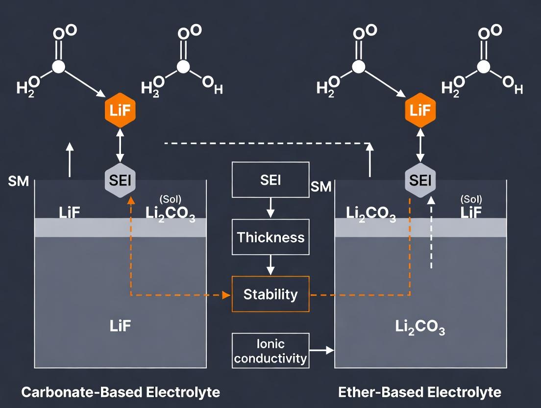
Visualization: SEI Formation Pathways Comparison
The Scientist's Toolkit: Key Research Reagents & Materials
Table 2: Essential Materials for SEI Research Experiments
| Item | Function/Description | Example Product/CAS |
|---|---|---|
| Electrolyte Solvents | Forms the bulk medium for Li⁺ transport; primary source of SEI components via reduction. | Ethylene Carbonate (EC, 96-49-1), 1,3-Dioxolane (DOL, 646-06-0) |
| Lithium Salts | Provides Li⁺ ions; anion influences SEI inorganic composition and stability. | Lithium Hexafluorophosphate (LiPF₆), Lithium Bis(trifluoromethanesulfonyl)imide (LiTFSI, 90076-65-6) |
| Anode Substrates | The working electrode where SEI forms and is characterized. | Copper foil (for Li plating studies), Silicon wafer chips (for model studies) |
| Reference Electrodes | Provides a stable potential reference for accurate electrochemical measurements. | Lithium metal wire/chip, Custom Li-based reference electrodes. |
| XPS Calibration Standards | Used to calibrate binding energy scale and identify chemical states in SEI. | Clean Au foil (Au 4f₇/₂ at 84.0 eV), Adventitious carbon (C 1s at 284.8 eV) |
| Cryo-TEM Sample Prep Tools | Enables transfer and preparation of air-/beam-sensitive SEI samples. | Vitrobot plunger, Cryo-transfer holder, Glovebox-integrated tools. |
The formation of a stable Solid Electrolyte Interphase (SEI) is critical for the performance and longevity of lithium-ion and next-generation metal batteries (e.g., Li-metal, Na-metal). This layer, formed from the reductive decomposition of electrolyte components during initial cycles, dictates Coulombic efficiency, cycle life, and safety. This comparison guide, framed within a thesis comparing carbonate and ether-based systems, objectively analyzes the distinct roles of core chemical components—solvent, salt, and additive—in SEI formation, supported by experimental data.
Comparative Analysis of Solvent Systems: Carbonates vs. Ethers
The primary solvent fundamentally dictates the decomposition pathway and the resulting SEI's chemical and mechanical properties.
Table 1: SEI Characteristics from Carbonate vs. Ether Solvent Systems
| Property | Linear/Cyclic Carbonates (e.g., EC, DMC, EMC) | Ethers (e.g., DME, DOL, TEGDME) |
|---|---|---|
| Typical Reduction Potential | ~0.8-1.2 V vs. Li/Li⁺ (EC reduces first) | >1.6 V vs. Li/Li⁺ (more stable) |
| Primary SEI Components | Li₂CO₃, ROCO₂Li, (CH₂OCO₂Li)₂, LiF (with LiPF₆) | LiR–O–R (alkoxides), Li₂O, LiOH |
| SEI Morphology | Inorganic-rich, dense, and brittle | Organic-rich, more flexible/polymer-like |
| Ionic Conductivity | Moderate | Generally higher |
| Mechanical Stability | High modulus, prone to cracking upon plating/stripping | Lower modulus, more accommodating of volume change |
| Compatibility | Excellent with graphite anodes | Prone to polysulfide shuttling (in Li-S), better for Li-metal |
| Key Limitation | Unstable with Li-metal (dendrite growth) | Oxidative instability at high voltage (>4 V) |
Experimental Protocol: Potentiostatic Hold for SEI Formation Analysis
- Cell Assembly: Assemble a coin cell (CR2032) with the working electrode (e.g., Cu foil for Li deposition, or graphite), Li-metal counter/reference electrode, and a glass fiber separator.
- Electrolyte Preparation: In an argon-filled glovebox (<0.1 ppm O₂/H₂O), prepare the test electrolyte (e.g., 1M LiPF₆ in EC:DMC 1:1 vol% vs. 1M LiTFSI in DOL:DME 1:1 vol%).
- Formation Cycle: Place the cell in a potentiostat/galvanostat. Apply a constant potential step (e.g., 0.1 V vs. Li/Li⁺ for carbonates, 0.01 V for ethers) for a specified duration (e.g., 10 hours) to induce controlled electrolyte reduction and SEI formation.
- Post-Mortem Analysis: Disassemble the cell in the glovebox. Wash the electrode with a pure solvent (e.g., DMC) to remove residual salts. Analyze the electrode surface using:
- XPS (X-ray Photoelectron Spectroscopy): For elemental and chemical bonding analysis of the SEI layer (detect C–O, C=O, Li–F, S–O bonds).
- SEM (Scanning Electron Microscopy): For morphology and thickness evaluation.
- AFM (Atomic Force Microscopy): For mechanical property mapping.
Salt-Derived SEI Component Formation
The anion significantly influences SEI inorganic composition, directly affecting Li⁺ transport and mechanical strength.
Table 2: Impact of Lithium Salt Anion on SEI Composition and Properties
| Lithium Salt | Primary SEI Inorganic Component | Decomposition Pathway & Key Property | Resulting SEI Characteristic |
|---|---|---|---|
| LiPF₆ | LiF | Thermal/chemical hydrolysis: PF₆⁻ + H₂O → POxFy + HF → LiF | Hard, high-modulus, enhances stability but can be brittle. |
| LiTFSI (LiN(SO₂CF₃)₂) | LiF, LiₓSOy, Li₃N | Reduction of –SO₂–CF₃ groups; N–S bond cleavage. | Forms a more organic-inorganic hybrid layer. Good Li⁺ conductivity. |
| LiFSI (LiN(SO₂F)₂) | LiF, LiₓSOy, Li₃N | Similar to LiTFSI but with higher tendency to form LiF. | Promotes a dense, LiF-rich SEI. Excellent for Li-metal anodes. |
| LiBOB (LiB(C₂O₄)₂) | Lithium Borates, Li₂C₂O₄ | Anion reduction forms a B–O/C–O containing polymeric layer. | Excellent film-forming ability on graphite, suppresses EC co-intercalation. |
| LiDFOB (LiBF₂C₂O₄) | LiF, Lithium Borates, Li₂C₂O₄ | Combined reduction pathways of LiBF₄ and LiBOB. | Forms a robust, multi-component SEI. Synergistic effects. |
Experimental Protocol: Anion Decomposition via Linear Sweep Voltammetry (LSV)
- Working Electrode: Use an inert electrode material like glassy carbon or platinum.
- Cell Setup: Three-electrode cell with Li-metal counter and reference electrodes.
- Measurement: Scan the potential from open-circuit voltage (OCV, ~3V) down to 0 V vs. Li/Li⁺ at a slow scan rate (e.g., 0.1 mV/s).
- Data Analysis: The onset reduction current peak indicates the electrochemical stability window and the reduction potential of the salt anion. A lower onset potential suggests greater stability against reduction. The current density correlates with the rate of SEI-forming reactions.
Additives as SEI Architects
Additives are used in small amounts (typically 0.5-5 wt%) to preferentially reduce and form a superior, protective SEI.
Table 3: Comparative Performance of Common SEI-Forming Additives
| Additive | Primary Function | Proposed Mechanism | Key Experimental Outcome (vs. Baseline) |
|---|---|---|---|
| Fluoroethylene Carbonate (FEC) | SEI former for Si anodes, Li-metal. | Reduces before solvents, forming a flexible, LiF and polyene-rich SEI. | Increases cycle life of Si anode by >50%. Reduces Li dendrite formation. |
| Vinylene Carbonate (VC) | Graphite SEI stabilizer. | Polymerizes to form a poly(VC) elastomeric network atop inorganic SEI. | Improves 1st cycle efficiency of graphite by 5-10%. Reduces gas generation. |
| Lithium Nitrate (LiNO₃) | Anode protector (esp. in Li-S). | Reduces to form Li₃N (high Li⁺ conductivity) and LiₓNOy species. | Suppresses polysulfide shuttle; enables >100 stable cycles in Li-S cells. |
| 1,3,2-Dioxathiolane 2,2-Dioxide (DTD) | Multi-functional. | Co-polymerizes with VC or reduces to form LiSOₓ-rich, stable SEI. | Synergistic with VC; enhances thermal stability of SEI. |
| Lithium Difluorophosphate (LiDFP) | Cathode & Anode SEI improver. | Forms LiₓPOyFz and LiF-rich protective layers on both electrodes. | Boosts capacity retention of NMC811/Li cells from 60% to 80% after 200 cycles. |
Experimental Protocol: Quantifying Additive Efficacy via Coulombic Efficiency (CE) Measurement
- Cell Configuration: Li || Cu asymmetric cell (N/P ratio >> 1).
- Cycling Procedure: Cycle the cell with a fixed capacity of Li plating (e.g., 1 mAh/cm²) followed by stripping to a high cutoff voltage (e.g., 1 V) at a constant current density.
- Calculation: Coulombic Efficiency (CE) = (Charge from Li stripping) / (Charge used for Li plating) for each cycle. A higher average CE indicates less "dead Li" and a more efficient SEI.
- Analysis: Plot CE vs. cycle number. The electrolyte with the optimal additive will show the highest, most stable CE profile, converging to >99.5% for practical applications.
Diagram Title: Core Component Pathways to Final SEI Properties
Diagram Title: Experimental Workflow for SEI Characterization
The Scientist's Toolkit: Key Research Reagent Solutions
| Reagent / Material | Primary Function in SEI Research | Key Consideration |
|---|---|---|
| Ethylene Carbonate (EC) | Benchmark cyclic carbonate solvent. High dielectric constant, forms effective SEI on graphite. | Hygroscopic; requires rigorous drying. Often used in mixtures with linear carbonates. |
| 1,2-Dimethoxyethane (DME) | Common ether solvent for Li-metal and Li-S batteries. Good solvating power for lithium polysulfides. | Low boiling point, highly flammable. Oxidizes at ~3.9 V. |
| Lithium Bis(trifluoromethanesulfonyl)imide (LiTFSI) | Widely used salt in ether electrolytes and for mechanistic studies. High solubility and conductivity. | Corrosive to Al current collectors above 3.8 V. Often paired with anti-corrosion additives. |
| Fluoroethylene Carbonate (FEC) | Critical additive for silicon and lithium-metal anode research. | Optimal concentration is system-dependent (often 2-10 wt%). Can deplete over cycling. |
| Lithium Nitrate (LiNO₃) | Essential additive for Li-S chemistry to modify anode SEI. | Limited solubility in carbonate electrolytes (~0.4 M). More soluble in ethers. |
| Copper Foil (as current collector) | Substrate for Li plating/stripping CE measurements. | Surface roughness and cleanliness critically affect nucleation uniformity. |
| Whatman Glass Fiber Separator | Inert separator for electrolyte compatibility tests. | Absorbs significant electrolyte volume; can influence cell impedance. |
Within the broader thesis on Solid Electrolyte Interphase (SEI) formation comparing carbonate versus ether-based electrolyte systems, the initial reduction pathways of solvent molecules are of paramount importance. These initial electron transfer events dictate the subsequent chemical cascade that forms the SEI, a critical component governing lithium metal anode cyclability and cell performance. This guide objectively compares the initial decomposition mechanisms for representative carbonates (ethylene carbonate - EC, dimethyl carbonate - DMC) and ethers (1,3-dioxolane - DOL, dimethoxyethane - DME), supported by experimental and computational data.
Initial Reduction Potentials and One-Electron Reduction Products
The first quantitative metric for comparing reduction pathways is the thermodynamic reduction potential. Lower (more negative) potentials indicate greater stability against reduction at the anode interface.
Table 1: Calculated Initial Reduction Potentials and Primary Products
| Solvent | Molecular Class | Calculated LUMO Energy (eV) | Estimated Reduction Potential vs. Li+/Li (V) | Primary One-Electron Reduction Product | Experimental Method (Reference) |
|---|---|---|---|---|---|
| Ethylene Carbonate (EC) | Cyclic Carbonate | -0.58 | ~0.9 | EC•− Radical Anion (ring opening) | DFT (B3LYP/6-311+G), CV |
| Dimethyl Carbonate (DMC) | Linear Carbonate | -0.21 | ~1.2 | DMC•− Radical Anion (C-O cleavage) | DFT (PBE/6-311+G), CV |
| 1,3-Dioxolane (DOL) | Cyclic Ether | 0.35 | ~1.6 | DOL•+ Radical Cation (oxidation prone) / Cleaved Radical | DFT (M062X/6-311+G), CV |
| Dimethoxyethane (DME) | Linear Ether | 0.72 | >2.0 | Stable against direct reduction | DFT (ωB97XD/6-311+G), CV |
Note: CV = Cyclic Voltammetry; DFT values are illustrative from literature. Ethers generally have higher LUMO energies, making them more stable against reduction on Li metal.
Experimental Protocol for Cyclic Voltammetry (CV) Measurement:
- Cell Assembly: A standard three-electrode electrochemical cell is used. Working electrode: Glassy carbon or copper disk. Counter electrode: Lithium metal. Reference electrode: Lithium metal.
- Electrolyte Preparation: 1.0 M LiTFSI or LiPF6 salt is dissolved in the pure target solvent (EC, DMC, DOL, DME). Preparation occurs in an argon-filled glovebox (H2O, O2 < 0.1 ppm).
- Measurement: The cell potential is scanned from open-circuit voltage (OCV) to a cathodic limit (e.g., 0 V vs. Li+/Li) at a slow scan rate (e.g., 1 mV/s).
- Data Analysis: The onset of cathodic current is identified as the reduction potential. The peak current and charge passed are integrated to compare reduction kinetics and extent.
Decomposition Pathways and SEI Precursors
Following initial electron transfer, the radical anions or neutral radicals undergo specific chemical reactions, generating the species that constitute the SEI.
Table 2: Subsequent Decomposition Pathways and Key SEI Components
| Solvent | Initial Reduced Species | Primary Decomposition Reaction | Key SEI Components Formed | Analytical Evidence |
|---|---|---|---|---|
| EC | EC•− | Ring opening followed by combination or further reduction | Lithium ethylene dicarbonate (LEDC), Li2CO3, (CH2OCO2Li)2 | FTIR, XPS, MS |
| DMC | DMC•− | Methoxy group loss, forming •CO3- and CH3• | Li2CO3, LiCH3, CH3OLi | DFT-MD, GC-MS |
| DOL | (Stable to reduction; can polymerize) | Cationic polymerization initiated by Lewis acid (e.g., Li+) or radicals | Poly-DOL, oligomeric ethers | NMR, GPC, ToF-SIMS |
| DME | (Stable to reduction) | May co-reduce with salts or participate in anion-derived SEI | Limited organic contribution; SEI dominated by salt anions (e.g., LiF from LIFSI) | XPS, Cryo-EM |
Experimental Protocol for SEI Analysis via X-ray Photoelectron Spectroscopy (XPS):
- Sample Preparation: Li metal is immersed in the electrolyte of interest and held at a fixed potential (e.g., 0.5 V vs. Li+/Li) for a set duration to form SEI. Electrodes are then retrieved and thoroughly washed with a pure solvent (e.g., DME) to remove residual salt.
- Transfer: Electrodes are transferred from the glovebox to the XPS spectrometer using an airtight transfer vessel to prevent air exposure.
- Measurement: Spectra are acquired using a monochromatic Al Kα source. High-resolution scans are taken for key elements: C 1s, O 1s, F 1s, P 2p (if applicable).
- Data Analysis: Peaks are deconvoluted using fitting software. Peaks are assigned to specific chemical species (e.g., C 1s: C-C/C-H (~284.8 eV), C-O (~286.5 eV), O-C=O (~289 eV) for carbonates; F 1s: LiF (~685 eV), C-F (~688 eV)).
Visual Comparison of Reduction Pathways
The Scientist's Toolkit: Key Research Reagent Solutions
Table 3: Essential Materials for Electrolyte Reduction Studies
| Item/Chemical | Function/Relevance | Example Supplier/Notes |
|---|---|---|
| Anhydrous Solvents (EC, DMC, DOL, DME) | High-purity solvents are critical to avoid side reactions from water/acid impurities. | Sigma-Aldrich (H2O < 20 ppm), battery grade. |
| Lithium Salts (LiPF6, LiTFSI, LiFSI) | Salt anion significantly influences reduction pathway and SEI composition. | Tomiyama Pure Chemical, battery grade. |
| Electrochemical Cell (Swagelok-type or Coin Cell) | For controlled SEI formation and electrochemical testing. | EL-CELL, MIT Corporation. |
| Air-free Transfer Vessel | To transfer air-sensitive SEI samples to analytical equipment (XPS, SEM). | Kurt J. Lesker Company. |
| Reference Electrolyte (e.g., 1M LiPF6 in EC:DMC) | Standard baseline for comparison in electrochemical tests. | Novolyte Technologies / BASF. |
| Deuterated Solvents for NMR (e.g., d4-DME) | For analyzing decomposition products in solution via NMR spectroscopy. | Cambridge Isotope Laboratories. |
| Lithium Metal Foil (High Purity) | Working/Counter electrode for SEI formation studies. | Honjo Metal, thickness 0.2-0.5 mm. |
| Glass Fiber or Celgard Separator | Physical separator in electrochemical cells. | Whatman (GF/F), Celgard 2325. |
Influence of Li Salt (LiPF6, LiTFSI, LiFSI) on SEI Composition and Morphology
Within the broader investigation of Solid Electrolyte Interphase (SEI) formation, a fundamental dichotomy exists between carbonate-based and ether-based electrolyte systems. While the solvent choice dictates the primary reduction pathways, the lithium salt anion plays a critical and often dominant role in determining the ultimate inorganic/organic composition, mechanical stability, and morphological homogeneity of the SEI. This guide compares the influence of three predominant Li salts—LiPF₆, LiTFSI, and LiFSI—in these distinct solvent environments, synthesizing current experimental data to elucidate their comparative impact on SEI characteristics and, consequently, electrochemical performance.
Table 1: Influence of Li Salt on SEI Properties and Cell Performance
| Property / Metric | LiPF₆ (in EC/DMC) | LiTFSI (in DOL/DME) | LiFSI (in EC/DMC or Ethers) |
|---|---|---|---|
| Primary SEI Components | Li₂O, LiF, Li₂CO₃, (CH₂OCO₂Li)₂ | Li₂O, LiF, Organic Li sulfones | LiF, Li₂O, Li₂S, Li₂SO₃, Li₃N |
| Key SEI Organic Species | ROCO₂Li, PEO-like oligomers | Rich in R-CH₂OLi, sulfonates | Minimal organics, N/S-rich inorganics |
| SEI Morphology | Heterogeneous, thicker (~50-100 nm) | More uniform, moderate thickness | Highly uniform, thin (~10-30 nm), dense |
| Ionic Conductivity (SEI) | Moderate | Lower | High |
| Mechanical Stability | Brittle, prone to fracture | Flexible, more adaptive | Hard, yet stable and coherent |
| Li⁺ Transference Number (t₊) | ~0.2-0.4 | ~0.2-0.3 | ~0.4-0.6 |
| Cycle Efficiency (Li metal) | Low (< 90%) | Moderate (~92-96%) | High (> 97%) |
| Typical Voltage Stability | ~4.3 V vs. Li/Li⁺ | ~3.9 V vs. Li/Li⁺ | > 4.5 V vs. Li/Li⁺ |
| Major Decomposition Pathway | PF₆⁻ + 2e⁻ + 2Li⁺ → LiF + LiₓPFᵧ | TFSI⁻ reduction: -SO₂- cleavage | FSI⁻ reduction: N-S bond cleavage |
Detailed Experimental Protocols
3.1. In Situ Electrochemical Quartz Crystal Microbalance (EQCM) for SEI Mass Deposition
- Objective: To measure the real-time mass change during the initial SEI formation cycle.
- Methodology:
- A gold-coated quartz crystal (working electrode) is assembled in a coin-cell configuration vs. Li metal.
- The cell is filled with the electrolyte of interest (e.g., 1M LiFSI in DME).
- A constant current density (e.g., 0.1 mA/cm²) is applied for a fixed capacity (e.g., 0.5 mAh/cm²).
- The resonant frequency shift (Δf) of the crystal is monitored simultaneously and converted to mass change (Δm) using the Sauerbrey equation: Δm = -C * Δf, where C is the mass sensitivity constant.
- The derivative d(Δm)/d(Q) provides insight into the density and compactness of the deposited SEI.
3.2. X-ray Photoelectron Spectroscopy (XPS) Depth Profiling for SEI Composition
- Objective: To determine the elemental composition and chemical states across the SEI depth.
- Methodology:
- Li metal or anode samples are cycled (1-5 cycles) and retrieved in an Ar-filled glovebox.
- Samples are transferred via an inert vacuum transfer vessel to avoid air exposure.
- XPS spectra (C 1s, O 1s, F 1s, P 2p, S 2p, N 1s) are acquired using a monochromatic Al Kα source.
- Sequential argon ion sputtering (e.g., 30-500 eV, 30s intervals) is used to etch through the SEI layer.
- Spectra are fitted with calibrated binding energies for species identification (e.g., LiF at ~685 eV in F 1s, -SO₂- at ~169 eV in S 2p).
3.3. Cryogenic Electron Microscopy (Cryo-EM) for SEI Morphology
- Objective: To visualize the native, nanoscale morphology of the SEI without beam damage.
- Methodology:
- Cycled anode samples (e.g., Li metal) are washed with a pure solvent (e.g., DME) and retrieved.
- A small sample fragment is mounted on a TEM grid and rapidly plunged into liquid ethane to form a vitreous ice layer, preserving the SEI structure.
- The sample is transferred and maintained at cryogenic temperatures (< -170°C) in the microscope.
- High-resolution imaging is performed at low electron doses (e.g., 10-20 e⁻/Ų) to prevent artifact induction.
Visualized Pathways and Workflows
Diagram 1: SEI Formation Influence Pathway (100 chars)
Diagram 2: Multi-Technique SEI Analysis Workflow (99 chars)
The Scientist's Toolkit: Key Research Reagent Solutions
Table 2: Essential Materials for SEI Formation Studies
| Item / Reagent | Function / Role in SEI Research | Key Consideration |
|---|---|---|
| Anhydrous Solvents (EC, DMC, EMC, DOL, DME) | Forms the electrolyte medium; primary source of organic SEI components via solvent reduction. | Water content < 10 ppm is critical. Purify over molecular sieves/Al₂O₃. |
| Lithium Salts (LiPF₆, LiTFSI, LiFSI, LiClO₄) | Primary source of inorganic SEI components (LiF, LiₓPFᵧ, Li₃N, Li₂S). Dictates anion-driven SEI chemistry. | High purity (>99.9%), store in dry environment. LiPF₆ is thermally/ hydrolytically unstable. |
| Lithium Metal Foil (Anode) | Standard counter/reference electrode; substrate for studying Li metal SEI. | Thickness, surface roughness, and native passivation layer affect reproducibility. |
| Copper Foil (Working Electrode) | Inert substrate for Li plating/stripping studies and SEI formation ex situ analysis. | Surface cleanliness and morphology are crucial. Pre-cleaning with acid is standard. |
| Molecular Sieves (3Å/4Å) & Alumina (neutral) | For in-lab electrolyte drying and purification to maintain ultralow H₂O content. | Must be activated by baking before use. |
| Argon-filled Glovebox | Provides inert atmosphere (O₂ & H₂O < 0.1 ppm) for all cell assembly and post-cycled sample handling. | Continuous purification and monitoring of atmosphere quality are mandatory. |
| Inert Transfer Vessel | Enables safe, air-free transfer of air-sensitive samples (e.g., cycled anodes) to surface analysis instruments (XPS, SEM). | Must maintain vacuum or inert gas pressure during transfer. |
The solid-electrolyte interphase (SEI) is a critical determinant of lithium-metal battery (LMB) performance and safety. Its formation is governed by complex interactions between thermodynamic stability and kinetic reaction rates of electrolyte components. This guide compares the SEI formed in conventional carbonate electrolytes against emerging ether-based systems, framing the discussion within ongoing research on stabilizing lithium-metal anodes.
Core Comparative Analysis: Carbonate vs. Ether Electrolytes
The fundamental differences in SEI properties stem from the distinct reduction pathways of these solvent classes.
| Driver & Property | Carbonate-Based Electrolytes (e.g., 1M LiPF₆ in EC:DEC) | Ether-Based Electrolytes (e.g., 1M LiTFSI in DOL:DME) |
|---|---|---|
| Thermodynamic Driver | High reduction potential (~0.8-1.2 V vs. Li⁺/Li) of cyclic carbonates (EC). | Lower reduction potential (~1.6-1.9 V vs. Li⁺/Li) of linear ethers (DOL, DME). |
| Primary Reduction Products | Li₂CO₃, (CH₂OCO₂Li)₂, ROCO₂Li, polymeric species. | Li₂O, LiF (from salt), oligomeric ethers (poly-DOL). |
| SEI Morphology | Inorganic-rich, heterogeneous, brittle, and thick (50-200 nm). | Organic/Polymer-rich, homogeneous, flexible, and thin (<50 nm). |
| Ionic Conductivity (Li⁺) | Moderate (~10⁻³ S/cm) but high impedance from poor Li⁺ transport in inorganic matrix. | High (~10⁻² to 10⁻³ S/cm) due to organic/polymer matrix facilitating Li⁺ hopping. |
| Mechanical Properties | Brittle; cracks under Li plating stress, leading to fresh Li exposure and electrolyte consumption. | Flexible/Elastic; accommodates Li volume changes, maintaining passivation. |
| Kinetic Stability (CE of Li plating/stripping) | Low initial Coulombic Efficiency (CE: 80-95%); unstable, decaying over cycles. | High initial CE (>97-99.5%); stable over hundreds of cycles in optimized cells. |
| Key Failure Mode | Uncontrolled, continual SEI growth ("mossy"/"dead" Li) due to cracking and repair cycles. | Li dendrite penetration if SEI is too mechanically soft; less electrolyte depletion. |
Experimental Protocols for SEI Analysis
Key methodologies for characterizing SEI differences are outlined below.
Protocol A: In Situ Electrochemical Quartz Crystal Microbalance (EQCM)
- Objective: Quantify mass deposited per charge (SEI formation) in real-time.
- Method: A gold-coated quartz crystal (working electrode) is polarized in a Li⁺-containing electrolyte against Li metal. The frequency shift (Δf) is measured during a slow cyclic voltammetry (CV) scan (0.1 mV/s) from OCV to 0 V vs. Li⁺/Li. The Sauerbrey equation converts Δf to mass change. Carbonates show large, irreversible mass gain on first scan. Ethers show minimal, often reversible mass change.
Protocol B: X-ray Photoelectron Spectroscopy (XPS) Depth Profiling
- Objective: Determine chemical composition and stratification of the SEI.
- Method: Li metal is cycled (e.g., 5 cycles at 0.5 mA/cm²), extracted, washed with inert solvent (e.g., DME), and transferred via an inert atmosphere vessel. Ar⁺ sputtering is used to etch the SEI layer sequentially. Spectra for C 1s, O 1s, F 1s, and Li 1s are collected at each depth. Carbonate SEI shows a Li₂CO₃-rich outer layer and Li₂O/LiR-rich inner layer. Ether SEI shows a uniform organic matrix with embedded LiF nanocrystals.
Protocol C: Cryogenic Electron Microscopy (Cryo-EM)
- Objective: Resolve the native morphology and microstructure of SEI and Li deposits.
- Method: Cycled Li metal anode is extracted, washed, and plunge-frozen in liquid ethane to preserve delicate structures. Transferred under cryo-conditions, the sample is imaged at low temperatures (~100 K) using a transmission electron microscope (TEM). This reveals the nanocrystalline inorganic particles in carbonate SEI versus the amorphous, conformal polymer-like ether SEI.
Key Visualizations
Title: SEI Formation Pathways for Carbonate vs Ether Electrolytes
Title: Experimental Workflow for SEI Characterization
The Scientist's Toolkit: Essential Research Reagents & Materials
| Item | Function in SEI Research | Example Product/Chemical |
|---|---|---|
| Anhydrous Electrolyte Solvents | Base for formulating electrolytes; purity is critical to avoid side reactions. | Ethylene Carbonate (EC, ≥99.9%), Diethyl Carbonate (DEC), 1,3-Dioxolane (DOL, anhydrous), 1,2-Dimethoxyethane (DME, anhydrous). |
| Lithium Salts | Provide Li⁺ conductivity; anion choice (PF₆⁻, TFSI⁻, FSI⁻) critically influences SEI. | Lithium hexafluorophosphate (LiPF₆), Lithium bis(trifluoromethanesulfonyl)imide (LiTFSI), Lithium bis(fluorosulfonyl)imide (LiFSI). |
| Chemical Additives | Modify SEI properties through preferential reduction. | Fluoroethylene carbonate (FEC, 1-10 wt%), Lithium nitrate (LiNO₃, 0.5-2 wt%), Vinylene carbonate (VC). |
| Inert Atmosphere Equipment | Enables handling of air/moisture-sensitive materials (Li metal, electrolytes). | Glovebox (H₂O/O₂ < 0.1 ppm), Argon gas cylinder, Sealed transfer vessels. |
| Electrode Substrates | Well-defined surfaces for model studies. | Copper foil (battery grade), polished copper disks for EQCM, silicon wafers for model studies. |
| Reference Electrodes | Accurate potential control during SEI formation. | Lithium metal wire/reference electrode. |
| Electrolyte Purification Media | Removes residual water and acidic impurities. | Molecular sieves (3Å or 4Å), basic alumina. |
The Role of LiNO3 and Other Key Additives in Modifying SEI in Ether Electrolytes
This guide compares the efficacy of key additives, primarily lithium nitrate (LiNO₃), in modifying the solid electrolyte interphase (SEI) within ether-based electrolytes. The analysis is framed within a broader thesis comparing SEI formation in traditional carbonate versus ether-based systems, which are critical for next-generation lithium metal (Li⁰) and lithium-sulfur (Li-S) batteries.
Comparative Performance of Key SEI-Modifying Additives in Ether Electrolytes
The following table summarizes experimental data from recent studies on additive performance in model ether electrolytes (e.g., 1,3-Dioxolane / 1,2-Dimethoxyethane, DOL/DME).
Table 1: Performance Comparison of Key Additives in Li-S and Li Metal Batteries
| Additive | Primary Function | Concentration (wt%) | Key Metric: Li Coulombic Efficiency (%) | Key Metric: Cycle Life (Cycles to 80% cap.) | SEI Composition (Key Identified Species) |
|---|---|---|---|---|---|
| LiNO₃ | Oxidizer, promotes inorganic-rich SEI | 0.5 - 2.0 | ~99.1 (Li⁺|Cu) | ~200 (Li⁺|S) | LiₓNOy, Li₂O, Li₃N, LiNₓOy |
| LiFSI (High Conc.) | SEI/Li+ conductor former | 10-20 (in DME) | ~99.3 | >250 | LiF, Li₂S, organic S/N species |
| CsPF₆ | Immobilizes anions, promotes uniform plating | 0.05 - 0.1 M | 98.8 | ~180 | CsF, LiF, organic carbonates |
| Li₂S₈ (Pre-added) | Forms Li₂S-rich interface | ~0.2 M S | 98.5 | ~220 (Li⁺|S) | Li₂S, Li₂S₂, polysulfides |
| VC (Vinylene Carbonate) | Polymerizable SEI former | 1-2 | 97.5 (in ether) | ~120 | Poly(VC), ROCO₂Li |
| Control (No Additive) | Baseline | N/A | <96.5 | <50 | ROLi, RCOOLi, Li₂O₂ (poor) |
Table 2: SEI Property Comparison: Carbonate vs. Ether + LiNO₃ Systems
| SEI Property | Carbonate Electrolyte (e.g., 1M LiPF₆ in EC/DEC) | Ether Electrolyte (DOL/DME) + 2% LiNO₃ |
|---|---|---|
| Primary Organic Component | Polycarbonates, (CH₂OCO₂Li)₂ (from EC) | Polyethers, ROLi (from solvent decomposition) |
| Primary Inorganic Component | Li₂CO₃, LiF | LiₓNOy, Li₃N, Li₂O |
| Mechanical Robustness | Brittle, prone to fracture | More flexible, better adhesion |
| Ionic Conductivity (Li⁺) | Moderate | Higher (due to Li₃N, LiNₓOy) |
| Function for Li Metal | Poor, uneven plating | Enables denser, dendrite-suppressed plating |
| Function for Li-S | Ineffective (polysulfide shuttle) | Excellent shuttle suppression via LiₓNOy layer |
Experimental Protocols for Key Studies
Protocol 1: Evaluating Li Coulombic Efficiency via Li\|Cu Cell
- Cell Assembly: Assemble CR2032 coin cells with a Li metal chip as the counter/reference electrode, a Cu foil working electrode, and a glass fiber separator. The electrolyte is 1.0M LiTFSI in DOL/DME (1:1, v/v) with/without additives.
- Electrochemical Protocol: Cycle using a potentiostat. Deposit a fixed capacity of Li (e.g., 1 mAh cm⁻²) onto the Cu at a current density (e.g., 0.5 mA cm⁻²). Strip the deposited Li to a cutoff voltage of 1.0 V vs. Li⁺/Li.
- Data Analysis: Coulombic Efficiency (CE) = (Total Li stripping charge) / (Total Li plating charge) per cycle. Average CE over >100 cycles is reported.
Protocol 2: Symmetric Li\|Li Cell Cycling for Stability
- Cell Assembly: Symmetric cell with two identical Li metal electrodes and the electrolyte of interest.
- Cycling Protocol: Cycle the cell with a fixed plating/stripping capacity (e.g., 1 mAh cm⁻²) at a constant current density (e.g., 1 mA cm⁻²).
- Analysis: Monitor the voltage hysteresis over time. A stable, low overpotential indicates a stable SEI. Rapid overpotential increase signifies SEI failure and dendrite growth.
Protocol 3: SEI Composition Analysis via XPS
- Sample Preparation: After cycling, disassemble cells in an Ar-filled glovebox. Retrieve the Li or electrode surface and rinse with pure DME solvent to remove residual salts/solvents.
- Transfer: Use an airtight transfer vessel to move samples to the XPS instrument without air exposure.
- Measurement: Acquire high-resolution spectra for C 1s, O 1s, N 1s, F 1s, S 2p, and Li 1s regions.
- Deconvolution: Fit peaks with known binding energies for species like LiF (~684.8 eV), Li₂O (~528.5 eV), Li₃N (~398.5 eV), ROLi (~531.5 eV), and LiNₓOy (~399-407 eV).
Visualizing the Role of LiNO₃ in Ether SEI Formation
SEI Formation with LiNO3 in Ether
The Scientist's Toolkit: Research Reagent Solutions
Table 3: Essential Materials for SEI Research in Ether Electrolytes
| Reagent/Material | Function in Research | Typical Purity/Details |
|---|---|---|
| 1,3-Dioxolane (DOL) | Cyclic ether solvent. Forms flexible organic SEI components. | Anhydrous, 99.8%, with molecular sieves. Must be tested for peroxide content. |
| 1,2-Dimethoxyethane (DME) | Linear ether solvent. Good salt solvator and Li⁺ transport. | Anhydrous, 99.8%, with molecular sieves. |
| Lithium Bis(trifluoromethanesulfonyl)imide (LiTFSI) | Common conducting salt for ether electrolytes. Influences SEI via anion reduction. | Battery grade, 99.95% trace metals. Dried under vacuum at 120°C. |
| Lithium Nitrate (LiNO₃) | Key additive. Oxidizer that decomposes to form LiₓNOy/Li₃N-rich, protective SEI. | Battery grade, 99.99%. Often pre-dissolved in electrolyte. |
| Lithium Foil | Anode material for Li metal battery research. | Thickness 0.25-0.75 mm, purity >99.9%. Freshly rolled before use. |
| Copper Foil (as substrate) | Working electrode for Li plating/stripping Coulombic efficiency tests. | Battery grade, cleaned with dilute acid and solvents. |
| Glass Fiber Separator | Electrolyte reservoir, inert to ether solvents and Li. | Whatman GF/A or GF/C, typically dried at 150°C under vacuum. |
| Polysulfide Solution (Li₂S₈) | For Li-S studies. Models cathode environment and can be used as a pre-passivation agent. | Synthesized from S₈ and Li₂S in specific stoichiometry in solvent. |
| Air-tight Sample Transfer Holder | For transporting air-sensitive SEI samples to analytical instruments (XPS, ToF-SIMS). | Stainless steel or polymeric vessel with sealed pouch. |
Advanced Characterization & Diagnostic Techniques for SEI Analysis
The Solid Electrolyte Interphase (SEI) is a dynamic, passivating layer critical to the performance and longevity of lithium metal anodes (LMAs) and next-generation batteries. Understanding its formation and evolution is paramount. This guide objectively compares the two principal analytical paradigms—In Situ (real-time, within the operational cell) and Ex Situ (post-mortem, after disassembly)—within the context of ongoing research comparing carbonate vs. ether-based electrolyte systems.
Core Comparison: Methodological Principles and Data Output
| Aspect | In Situ Analysis | Ex Situ Analysis |
|---|---|---|
| Temporal Resolution | Real-time, dynamic. Captures transient species & evolution. | Static snapshot at cycle endpoint. Misses intermediate states. |
| Spatial Integrity | SEI remains in native electrochemical environment. | SEI is extracted, risking contamination, relaxation, or damage. |
| Primary Techniques | Operando electrochemical quartz crystal microbalance (EQCM), in situ electrochemical AFM, in situ NMR/SERS, operando X-ray diffraction. | X-ray photoelectron spectroscopy (XPS), cryo-electron microscopy (cryo-EM), FTIR, ToF-SIMS (post-test). |
| Key Strength | Direct correlation of SEI property (e.g., mass, morphology) with electrochemical signal. | Higher spectral/spatial resolution and access to a broader suite of powerful characterization tools. |
| Major Limitation | Technical complexity; often lower resolution; indirect chemical identification. | Introduction of artifacts; loss of volatile components (e.g., Li₂O, organolithiums); no temporal data. |
| Ideal Use Case | Probing formation kinetics, mechanical stability, and dynamic response to potential sweeps. | Determining precise chemical composition and nanoscale structure of mature SEI layers. |
Experimental Data: Insights into Carbonate vs. Ether Systems
The following table summarizes key findings from recent studies employing these techniques to compare SEI formation in standard carbonate (e.g., 1M LiPF₆ in EC/DEC) and ether-based (e.g., 1M LiTFSI in DOL/DME) electrolytes.
| Electrolyte System | In Situ Technique & Finding | Ex Situ Technique & Finding | Implication for SEI |
|---|---|---|---|
| Carbonate (EC/DEC) | Operando EQCM: Shows large, irreversible mass gain early, indicating massive, heterogeneous decomposition. | Cryo-TEM/XPS: Reveals a thick (~20-50nm), multilayered SEI with inorganic Li₂CO₃, LiF, and Li₂O outer of organic polymers. | SEI is thick and resistive. Continuous consumption leads to capacity fade. |
| Ether (DOL/DME) | In Situ AFM: Shows rapid formation of a smooth, conformal layer that stabilizes; minimal continued growth. | XPS/ToF-SIMS: Detects a thin (~5-15nm), homogeneous, organic-rich SEI with polyethers and Li alkoxides from solvent polymerization. | SEI is thin, flexible, and more stable, promoting uniform Li⁺ flux and dendrite suppression. |
| Comparative Insight | In situ data shows ethers achieve passivation faster with less ongoing reaction. | Ex situ data confirms the fundamental chemical and morphological differences predicted by in situ trends. | Ether-derived SEI's superior dynamics and properties explain enhanced LMA cycling efficiency. |
Detailed Experimental Protocols
Protocol 1: Operando Electrochemical Quartz Crystal Microbalance (EQCM)
Objective: To measure mass change per unit area (Δm) of the electrode surface in real-time during SEI formation.
- Cell Assembly: A gold-coated quartz crystal (working electrode) is assembled in a hermetic EQCM cell with Li metal counter/reference electrodes.
- Electrolyte Introduction: The cell is filled with the target electrolyte (carbonate or ether) in an Ar-filled glovebox.
- Calibration: The Sauerbrey equation (Δf = -Cf * Δm) is used, where Δf is the resonant frequency shift and Cf is the sensitivity constant.
- Electrochemical Cycling: A constant current or potentiostatic hold (e.g., 0.01 mA cm⁻² for 1h) is applied to initiate Li plating/SEI formation.
- Data Acquisition: Simultaneously record current, potential, and frequency shift (Δf). Convert Δf to Δm using the Sauerbrey relation.
Protocol 2:Ex SituX-ray Photoelectron Spectroscopy (XPS) with Depth Profiling
Objective: To determine the elemental composition and chemical states across the SEI depth.
- SEI Formation & Termination: Li metal cells are cycled for a set number of cycles, then stopped at a specific state-of-charge.
- Sample Transfer: Cells are disassembled in glovebox. The Li anode with SEI is rinsed with a pure solvent (e.g., DME) to remove residual salts, then dried.
- Air-free Transfer: The sample is placed in a sealed, inert transfer vessel without exposure to atmosphere.
- XPS Analysis: The sample is introduced into the XPS chamber. A survey scan followed by high-resolution scans (C 1s, O 1s, F 1s, Li 1s) are acquired.
- Depth Profiling: Gentle sputtering with Ar⁺ ions is performed intermittently to etch the SEI, followed by XPS scans to build a compositional depth profile.
Visualizing the Analytical Workflow
Diagram Title: Complementary Pathways of SEI Analysis
The Scientist's Toolkit: Key Research Reagent Solutions
| Reagent / Material | Function in SEI Research |
|---|---|
| 1,3-Dioxolane (DOL) / 1,2-Dimethoxyethane (DME) | Ether-based solvent blend for forming organic-rich, flexible SEI on LMAs. Often with LiNO₃ additive. |
| Ethylene Carbonate (EC) / Diethyl Carbonate (DEC) | Standard carbonate solvent blend. Forms inorganic-rich, brittle SEI. Baseline for comparison. |
| Lithium bis(trifluoromethanesulfonyl)imide (LiTFSI) | Common Li salt for ether electrolytes. Contributes to SEI organic components and LiF. |
| Lithium hexafluorophosphate (LiPF₆) | Common Li salt for carbonate electrolytes. Source of LiF in SEI via decomposition. |
| Lithium Nitrate (LiNO₃) | Critical additive for ether electrolytes. Promotes formation of beneficial LiₓNOy/Li₂O species in SEI. |
| Deuterated Solvents (e.g., d⁴-DME, d⁶-EC) | Used for in situ NMR studies to track solvent consumption and decomposition pathways in real time. |
| Cryogenic Transfer Holder | Enables contamination-free, water-free transfer of air-sensitive battery samples to instruments like SEM/TEM/XPS. |
Within the critical study of solid electrolyte interphase (SEI) formation, comparing carbonate versus ether-based electrolyte systems, chemical fingerprinting is essential. Spectroscopic techniques provide the necessary surface and bulk analytical data to decode SEI composition, structure, and evolution. This guide objectively compares the performance of X-ray Photoelectron Spectroscopy (XPS), Fourier-Transform Infrared Spectroscopy (FTIR), and Raman Spectroscopy in this specific research context.
Performance Comparison & Experimental Data
The following table summarizes the core capabilities and typical experimental outputs of each technique when applied to SEI analysis on lithium metal anodes.
Table 1: Comparative Performance of Spectroscopic Techniques for SEI Fingerprinting
| Aspect | XPS | FTIR (ATR mode) | Raman Spectroscopy |
|---|---|---|---|
| Primary Information | Elemental identity, chemical state, & quantitative atomic % (top 5-10 nm). | Molecular functional groups & organic compound identification (top 0.5-5 µm). | Molecular vibrations, crystal structure, carbon ordering (µm-scale depth). |
| Spatial Resolution | 10-200 µm (microfocus). | 0.5-1 mm (ATR crystal contact area). | ~1 µm (confocal). |
| Detection Sensitivity | ~0.1-1 at%. | ~1% for major components. | Weak for fluorescent samples; enhanced by SERS. |
| Key SEI Signals | Li 1s (LiF, Li₂O, Li₂CO₃), C 1s (C-C, C-O, C=O), O 1s, F 1s. | C=O stretch (~1650-1800 cm⁻¹), CO₃²⁻ stretch (~1450, 850 cm⁻¹), C-O-C stretch (~1100 cm⁻¹). | Diamond-like carbon (DLC) bands (1350 cm⁻¹ D, 1580 cm⁻¹ G), Li₂CO₃ (1090 cm⁻¹), solvent peaks. |
| Sample Environment | Ultra-high vacuum required. | Ambient or controlled atmosphere. | Ambient, in-situ cells possible. |
| Quantitative Strength | Excellent, with appropriate sensitivity factors. | Semi-quantitative, relies on reference spectra. | Semi-quantitative; intensity depends on laser power, focus. |
| Key Limitation for SEI | UHV may alter volatile SEI components; limited to near-surface. | Poor sensitivity to inorganic Li species (e.g., Li₂O). | Fluorescence from organics can swamp signal; laser may degrade sample. |
Table 2: Example Experimental Data from SEI on Li in Carbonate vs. Ether Electrolyte Data derived from recent studies (representative values).
| SEI Component | Technique | Signal in Carbonate-based SEI | Signal in Ether-based SEI | Inference |
|---|---|---|---|---|
| Lithium Fluoride (LiF) | XPS (F 1s) | Strong peak at ~685 eV (High atomic % ~15-25%) | Weak or absent peak | LiF-rich SEI in carbonate due to PF₆⁻/Li salt decomposition. |
| Polyethylene Oxide (PEO) | FTIR | Absent | Strong C-O-C stretch at ~1100 cm⁻¹ | Ether solvent polymerization forms flexible organic layer. |
| Lithium Alkyl Carbonates (ROCO₂Li) | FTIR / XPS | Strong C=O (~1650 cm⁻¹), O=C-O (~289 eV in C 1s) | Moderate to weak | Primary reduction product of cyclic carbonates (EC). |
| Graphitic/Disordered Carbon | Raman | D/G band ratio (ID/IG) ~0.8-1.2 | ID/IG typically lower (~0.5-0.8) | More disordered carbon in carbonate-derived SEI. |
| Lithium Oxide (Li₂O) | XPS (O 1s) | Distinct peak ~528-529 eV | Often absent or minimal | Prevalent inorganic component in carbonate systems. |
Detailed Experimental Protocols
Protocol 1: XPS Analysis of SEI on Lithium Metal
Objective: To determine the elemental composition and chemical states of the SEI formed after cycling in different electrolytes.
- Sample Preparation: Cycle Li-metal coin cells (vs. Li or cathode) in target electrolyte. Disassemble in an Ar-filled glovebox (H₂O, O₂ < 0.1 ppm). Wash electrode with pure dimethyl carbonate (DMC) solvent to remove residual salts. Dry under vacuum.
- Transfer: Mount sample on a transfer holder without air exposure. Use an airtight transfer vessel to introduce the sample into the XPS load lock.
- Measurement: Acquire survey spectra (0-1200 eV) to identify elements. Collect high-resolution spectra for key regions: C 1s, O 1s, F 1s, Li 1s. Use a monochromatic Al Kα source (1486.6 eV). Pass energy: 20-50 eV for high-res, 100-150 eV for surveys.
- Data Analysis: Apply charge correction referencing adventitious carbon C 1s peak to 284.8 eV. Deconvolute peaks using appropriate Gaussian-Lorentzian curves. Quantify using relative sensitivity factors (RSFs) provided by instrument manufacturer.
Protocol 2:In-SituATR-FTIR Monitoring of SEI Formation
Objective: To observe the dynamic formation of organic SEI components during electrolyte reduction.
- Cell Setup: Use an in-situ electrochemical ATR cell with a silicon or diamond crystal as the working electrode (or coated with Cu/Li).
- Baseline: Introduce the pure electrolyte into the cell and acquire a background spectrum.
- Operando Measurement: Apply a constant cathodic potential (e.g., 0.5 V vs. Li/Li⁺) to the working electrode. Continuously collect FTIR spectra (e.g., every 30 seconds) at 4 cm⁻¹ resolution over 4000-650 cm⁻¹ range.
- Data Processing: Subtract the initial background spectrum. Plot absorbance vs. wavenumber over time. Identify emerging peaks corresponding to reduction products (e.g., Li₂CO₃, polyethylene oxide oligomers).
Protocol 3: Confocal Raman Mapping of SEI Heterogeneity
Objective: To map the spatial distribution of key chemical phases (e.g., Li₂CO₃, carbon species) across the SEI.
- Sample Prep: Prepare cycled electrodes as in Protocol 1. For air-sensitive samples, use a sealed microscopy stage with a quartz window.
- Calibration: Calibrate the spectrometer using a silicon wafer peak at 520.7 cm⁻¹.
- Mapping: Define a region of interest (e.g., 50x50 µm). Set laser wavelength (commonly 532 nm or 633 nm) and power (<1 mW to avoid damage). Acquire a spectrum at each pixel with 1 µm step size.
- Analysis: Generate chemical maps by integrating the intensity of characteristic peaks (e.g., 1090 cm⁻¹ for Li₂CO₃, 1350 & 1580 cm⁻¹ for D and G bands). Calculate D/G intensity ratio maps to assess carbon disorder.
Visualizations
Decision Flow for SEI Spectroscopy Technique Selection
SEI Formation Pathways & Key Spectroscopic Detectables
The Scientist's Toolkit: Key Research Reagent Solutions
Table 3: Essential Materials for SEI Spectroscopic Analysis
| Material / Reagent | Function in SEI Research |
|---|---|
| High-Purity Lithium Foil (99.9%) | Standard anode material for SEI formation studies. Consistency is critical for reproducible spectra. |
| Anhydrous Electrolyte Salts (LiPF₆, LiTFSI) | Source of Li⁺ and anions (PF₆⁻, TFSI⁻) whose decomposition critically defines SEI inorganic composition. |
| Deuterated Solvents (d-DMC, d-EC) | Used for solvent structure study in Raman/FTIR and for preparing electrolytes for NMR validation of spectroscopy data. |
| Single Crystal Si or Diamond ATR Crystals | The internal reflection element for in-situ FTIR, enabling sensitive surface measurements of SEI formation. |
| Argon-filled Glovebox (H₂O/O₂ < 0.1 ppm) | Essential environment for preparing and handling air-sensitive electrodes (Li metal, SEI layers) prior to analysis. |
| Air-Tight XPS/ Raman Transfer Holders | Preserves the pristine, unoxidized state of the SEI during transfer from glovebox to spectrometer. |
| Reference Compounds (Li₂CO₃, LiF, Li₂O powders) | Critical for obtaining standard reference spectra to deconvolute and assign peaks in complex SEI data. |
| SERS-Active Substrates (Au nanoparticles on Si) | Can enhance weak Raman signals from thin SEI layers, allowing detection of trace components. |
In the study of Solid Electrolyte Interphase (SEI) formation, comparing carbonate versus ether-based electrolyte systems, microscopy provides critical structural and morphological insights. Scanning Electron Microscopy (SEM), Transmission Electron Microscopy (TEM), and Atomic Force Microscopy (AFM) are indispensable tools, each offering unique capabilities for characterizing SEI layer thickness, homogeneity, crystallinity, and mechanical properties.
Comparative Analysis of Microscopy Techniques
Table 1: Core Performance Comparison of SEM, TEM, and AFM for SEI Characterization
| Feature | SEM | TEM | AFM |
|---|---|---|---|
| Resolution | ~0.5-10 nm (surface) | ~0.05-0.2 nm (atomic) | ~0.1-1 nm (lateral), ~0.01 nm (height) |
| Imaging Mode | Surface topography & composition | Internal structure & crystallography | 3D surface topography & nanomechanics |
| Sample Environment | High vacuum (typical) | High vacuum | Ambient, liquid, vacuum |
| Sample Preparation | Moderate (conductive coating often needed) | High (ultra-thin sections, FIB lift-out) | Minimal (minimal preparation) |
| Key SEI Metrics | Morphology, layer uniformity, cracking | Crystallinity, amorphous/crystalline phases, layer thickness | Roughness, modulus, adhesion, layer thickness |
| Quantitative Data | Qualitative & semi-quantitative morphology | Lattice imaging, SAED patterns for phase ID | Quantitative height, modulus, adhesion maps |
| Experimental Data (SEI Thickness) | 50-2000 nm (estimated from cross-section) | 2-100 nm (direct measurement from cross-sectional TEM) | 5-200 nm (direct height measurement) |
| Experimental Data (Reference) | See Protocol 1 | See Protocol 2 | See Protocol 3 |
Table 2: Suitability for SEI Studies in Different Electrolyte Systems
| Application | Carbonate-Based SEI (Typical) | Ether-Based SEI (Typical) | Optimal Technique |
|---|---|---|---|
| Layer Uniformity & Coverage | Inhomogeneous, patchy | More homogeneous, uniform | SEM, AFM |
| Nanomechanical Properties | Harder, brittle | Softer, more polymer-like | AFM (PeakForce QNM) |
| Crystallographic Phase Analysis | Li2O, LiF, Li2CO3 crystals | Dominantly amorphous, organic species | TEM (SAED, HRTEM) |
| In-situ/Operando Capability | Limited | Limited | Specialized TEM or AFM (in liquid cell) |
| Sensitivity to Beam Damage | Moderate (SEM), High (TEM) | High (organic components) | AFM (non-destructive) |
Experimental Protocols
Protocol 1: Cross-sectional SEM for SEI Thickness and Morphology
Objective: To visualize SEI layer morphology and measure its approximate thickness on electrode particles.
- Cell Disassembly: In an argon-filled glovebox (<0.1 ppm O2/H2O), disassemble cycled coin cells.
- Electrode Rinsing: Gently rinse the electrode (Li metal or anode) with pure dimethyl carbonate (DMC) solvent to remove residual electrolyte salts.
- Sample Preparation: Extract a small section of the electrode. For cross-section, use cryo-fracturing by immersing in liquid N2 and breaking, or prepare via Focused Ion Beam (FIB) milling for a precise cut.
- Conductive Coating: Sputter-coat the sample with a thin layer (3-5 nm) of Pt or Ir to prevent charging.
- Imaging: Transfer to SEM chamber. Image at accelerating voltages of 2-5 kV to minimize beam damage. Use secondary electron detector for topography and backscattered detector for compositional contrast.
Protocol 2: (S)TEM for SEI Nanostructure and Crystallography
Objective: To analyze the atomic structure and phase composition of the SEI layer.
- Sample Preparation (FIB lift-out): Protect the electrode surface with electron-beam and ion-beam deposited Pt. Use a Ga+ ion beam to extract a thin lamella (<100 nm thick) perpendicular to the SEI surface.
- Transfer: Weld the lamella to a TEM grid using a nanomanipulator and transfer using an air-tight holder or vacuum transfer vessel to prevent air exposure.
- Imaging & Analysis: Operate TEM/STEM at 80-300 kV. Use High-Resolution TEM (HRTEM) to lattice-fringe imaging. Acquire Selected Area Electron Diffraction (SAED) patterns to identify crystalline phases (e.g., Li2O, LiF). Perform Energy-Dispersive X-ray Spectroscopy (EDS) mapping for elemental distribution (C, O, F, P).
- Beam Damage Mitigation: Use low-dose imaging techniques and cryo-stages if analyzing ether-based SEI with organic components.
Protocol 3: AFM for SEI Topography and Mechanical Mapping
Objective: To measure SEI topography, thickness, and nanomechanical properties in situ.
- Sample Preparation: Rinse the cycled electrode as in Protocol 1. Attach the electrode to a steel puck using a conductive epoxy. For in-situ studies, use a sealed electrochemical AFM fluid cell.
- Imaging Mode Selection: Use PeakForce Tapping or Quantitative Nanomechanical Mapping (QNM) mode.
- Calibration: Calibrate the AFM probe's deflection sensitivity and spring constant prior to measurement.
- Topography Scan: In an inert atmosphere or under electrolyte, scan the SEI surface to obtain 3D topography and roughness (Ra, Rq).
- Mechanical Property Mapping: Use a diamond-coated or stiff Si probe to map DMT modulus, adhesion, and deformation simultaneously with topography. For thickness, scratch the SEI with a high force to expose the substrate and measure step height.
- Data Analysis: Use software (e.g., NanoScope Analysis) to extract quantitative parameters from the force-distance curves at each pixel.
Visualization
Title: Microscopy Workflow for SEI Analysis
Title: Technique Selection Guide for SEI Analysis
The Scientist's Toolkit: Key Research Reagent Solutions
Table 3: Essential Materials for SEI Microscopy Studies
| Item | Function/Description | Key Consideration for SEI |
|---|---|---|
| Dimethyl Carbonate (DMC), High Purity | Rinsing solvent to remove LiPF6 and Li salts from cycled electrodes. | Must be anhydrous (<10 ppm H2O). Preserves organic SEI components better than water. |
| Ar-filled Glovebox | Provides inert atmosphere for sample prep to prevent SEI decomposition. | O2/H2O levels <0.1 ppm are critical for ether-based SEI studies. |
| Conductive Sputter Coater (Pt/Ir) | Applies thin conductive layer to prevent charging in SEM. | Use thin coatings (3-5 nm) to avoid obscuring SEI nanostructure. |
| Focused Ion Beam (FIB) System | Prepares electron-transparent TEM lamella from specific SEI locations. | Low-energy milling final polish reduces Ga+ damage to sensitive SEI. |
| Vacuum Transfer Holder | Transfers air-sensitive TEM samples from glovebox to microscope. | Essential for preserving pristine SEI chemistry, esp. for ether systems. |
| AFM Fluid Cell with O-rings | Enables in-situ AFM imaging under electrolyte. | Material compatibility (e.g., fluorocarbon) with carbonate vs. ether electrolytes. |
| Diamond-Coated AFM Probes | Used for nanomechanical mapping (modulus) and scratching tests. | High stiffness (∼200 N/m) required for modulus measurement of hard carbonate SEI. |
| Cryo-Stage for TEM/SEM | Cools sample to liquid N2 temperatures during analysis. | Reduces beam damage and volatilization of organic, ether-based SEI layers. |
This guide compares three core electrochemical techniques for probing solid-electrolyte interphase (SEI) formation, framed within research comparing carbonate versus ether-based electrolyte systems. The diagnostics provide complementary data on SEI kinetics, stability, and ionic transport properties.
Technique Comparison & Experimental Data
Table 1: Comparative Performance of Electrochemical Techniques for SEI Analysis
| Technique | Primary Information Gained | Key Metric(s) | Typical Experimental Conditions (Li-metal anode) | Suitability for Carbonate vs. Ether Comparison |
|---|---|---|---|---|
| Electrochemical Impedance Spectroscopy (EIS) | SEI resistance, charge transfer kinetics, interfacial evolution. | RSEI (Ω cm²), Rct (Ω cm²). | Amplitude: 10 mV, Frequency: 1 MHz to 10 mHz, OCP or fixed bias. | Excellent for tracking RSEI growth (often larger in carbonates) and stability (often better in ethers). |
| Cyclic Voltammetry (CV) | Reductive electrolyte stability, SEI formation potentials, reversibility. | Peak potential (V vs. Li⁺/Li), peak current density (mA/cm²). | Scan rate: 0.1 - 1 mV/s, Range: OCP to ~0 V (vs. Li⁺/Li). | Critical for identifying initial reduction peaks (e.g., EC reduction ~0.8 V, DOL/DME >1.7 V). |
| Potentiostatic Holds (Chronoamperometry) | SEI passivation quality, continuous current decay, Li plating efficiency. | Passivation current (µA/cm²) at fixed time, Total charge passed (mC/cm²). | Hold potential: 0 - 0.2 V (vs. Li⁺/Li), Duration: 1-24 hours. | Directly measures current leakage (often higher in ethers) and passivation stability (often better in carbonates). |
Table 2: Representative Experimental Data from SEI Formation Studies
| Electrolyte System (1M Salt) | EIS: RSEI after 24h (Ω cm²) | CV: 1st Reduction Peak (V vs. Li⁺/Li) | Potentiostatic Hold (0.1 V): Current at 1h (µA/cm²) |
|---|---|---|---|
| Carbonate (EC:DEC, 1:1 v/v) | 120 ± 25 | 0.82 ± 0.05 | 2.1 ± 0.5 |
| Ether (DOL:DME, 1:1 v/v) | 45 ± 15 | 1.75 ± 0.10 | 8.5 ± 2.0 |
| Ether with LiNO₃ Additive | 85 ± 20 | 1.70 ± 0.10 | 3.0 ± 0.8 |
Experimental Protocols
Protocol 1: EIS for Tracking SEI Evolution
- Cell Assembly: Assemble a symmetric Li||Li or half-cell Li||Cu coin cell in an argon-filled glovebox.
- Initial SEI Formation: Perform one formation cycle via CV or a constant current discharge.
- EIS Measurement: Measure impedance at open circuit potential (or a chosen bias) over a frequency range of 1 MHz to 10 mHz with a 10 mV sinusoidal perturbation.
- Aging & Monitoring: Age the cell at a set temperature. Perform EIS measurements at regular intervals (e.g., 1h, 6h, 24h).
- Data Fitting: Fit spectra using an equivalent circuit model (e.g., Relectrolyte + (RSEI//CPESEI) + (Rct//CPEdl)).
Protocol 2: CV for Electrolyte Reduction Stability
- Cell Assembly: Assemble a three-electrode cell (Li working, Li counter, Li reference) or Li||Stainless Steel coin cell.
- Baseline Scan: Perform a CV scan from open circuit voltage to 2.5 V and back to OCP at 1 mV/s to confirm cleanliness.
- Formation Scan: Perform a critical scan from OCP down to 0.0 V vs. Li⁺/Li at a slow scan rate (0.1 mV/s). Record the reduction peaks.
- Cycling: Perform subsequent cycles (e.g., 5 cycles) to observe peak disappearance/evolution, indicating passivation.
Protocol 3: Potentiostatic Holds for Passivation Study
- Cell Assembly: Assemble a Li||Cu coin cell.
- Conditioning: Hold the cell at OCP for 1 hour to stabilize.
- Potential Step: Apply a constant potential step (e.g., 0.1 V vs. Li⁺/Li) for a prolonged period (e.g., 12 hours).
- Data Recording: Record the current response as a function of time. The decaying current indicates SEI formation and passivation.
- Post-Analysis: Integrate current-time data to calculate total charge consumed in SEI formation.
Visualizations
Diagnostics for SEI Analysis in Carbonate vs Ether Electrolytes
Integrated SEI Characterization Experimental Workflow
The Scientist's Toolkit: Key Research Reagent Solutions
Table 3: Essential Materials for SEI Electrochemical Diagnostics
| Item | Function in SEI Research | Example Product/Chemical |
|---|---|---|
| Carbonate Solvent Blend | Benchmark, high-dielectric solvent for comparative studies. | Ethylene Carbonate (EC) / Diethyl Carbonate (DEC) (1:1 v/v) |
| Ether Solvent Blend | Low-coordination power solvent for studying different SEI mechanisms. | 1,3-Dioxolane (DOL) / 1,2-Dimethoxyethane (DME) (1:1 v/v) |
| Lithium Salt | Provides conducting Li⁺ ions. | Lithium bis(trifluoromethanesulfonyl)imide (LiTFSI) or LiPF₆ |
| SEI Promoting Additive | Modifies SEI composition & properties (used in ethers). | Lithium nitrate (LiNO₃) |
| Electrode Substrate | Inert working electrode for deposition/SEI studies. | Copper foil (battery grade, 99.9%) |
| Counter/Reference Electrode | Lithium metal foil (high purity, 99.9%) | |
| Separator | Porous insulator between electrodes. | Glass fiber (Whatman) or Polypropylene (Celgard) |
| Electrochemical Cell | Container for testing. | CR2032-type coin cell hardware |
| Potentiostat/Galvanostat | Instrument for applying potential/current and measuring response. | Biologic VSP-300, Ganny Interface 1010E, or equivalent. |
Within the broader thesis investigating Solid Electrolyte Interphase (SEI) formation in carbonate versus ether-based electrolyte systems for lithium-metal batteries, analyzing decomposition products is critical. This guide compares the performance of Gas Chromatography-Mass Spectrometry (GC-MS) and Liquid Chromatography-Mass Spectrometry (LC-MS) for this specific analytical challenge, providing experimental data to inform method selection.
Comparison of Analytical Techniques
Table 1: Performance Comparison of GC-MS vs. LC-MS for SEI Product Analysis
| Parameter | GC-MS | LC-MS (ESI) | LC-MS (APCI) | |
|---|---|---|---|---|
| Optimal Analyte Type | Volatile, thermally stable small molecules (e.g., ethylene gas, alkyl carbonates). | Polar, thermally labile, higher MW species (e.g., oligomeric ethers, Li alkoxides). | Medium-polarity, less polar than ESI-suitable compounds. | |
| Sample Prep Complexity | High. Requires solvent extraction, often derivatization for non-volatile species. | Medium. Direct dissolution of SEI components in suitable solvent (e.g., DMSO). | Medium. Similar to ESI but with different solvent compatibility. | |
| Quantitative Precision | Excellent (RSD < 5%) with internal standards. | Good (RSD 5-10%). Can be affected by ion suppression. | Good (RSD 5-10%). Less ion suppression than ESI for some compounds. | |
| Sensitivity (LOD) | Low ppt-ppb range for most volatiles. | Low ppb range for targeted species. | Low ppb range. | |
| Identification Power | High. Reliable library matching for volatile organics. | High. Provides molecular weight and fragmentation for complex species. | High. Good for moderate polarity molecules with less fragmentation. | |
| Key Limitation | Cannot analyze non-volatile, ionic, or high-MW components directly. | Matrix effects can suppress ionization; requires method optimization. | Less effective for very polar or ionic species compared to ESI. | |
| Best Suited For | Carbonate system analysis: Li alkyl carbonates (e.g., LEDC, LEMC), solvents. | Ether system analysis: Polymeric/oligomeric species from DOL/DME decomposition. | Bridging analysis for semi-polar decomposition products common to both systems. |
Experimental Protocols
Protocol 1: GC-MS Analysis of Carbonate Electrolyte Decomposition Products
- SEI Harvesting: Disassemble cycled Li-metal coin cell in argon glovebox (<0.1 ppm H₂O/O₂). Rinse electrode with pure dimethyl carbonate (DMC) to remove residual electrolyte. Scrape SEI layer from electrode surface.
- Sample Derivatization: Dissolve scraped SEI in 1 mL of N,O-Bis(trimethylsilyl)trifluoroacetamide (BSTFA) with 1% TMCS. Heat at 70°C for 60 minutes to silylate alcohols, carboxylic acids, and other polar groups.
- GC-MS Analysis: Inject 1 µL of derivatized sample in splitless mode. Use a 30 m HP-5MS column. Oven program: 40°C (hold 2 min), ramp 10°C/min to 300°C (hold 10 min). Employ electron ionization (EI) at 70 eV. Identify compounds via NIST library matching and authentic standard retention times.
Protocol 2: LC-MS Analysis of Ether Electrolyte Decomposition Products
- SEI Solubilization: Harvest SEI from cycled electrode as in Protocol 1. Instead of derivatization, dissolve the sample in 1 mL of a 50:50 v/v mixture of dimethyl sulfoxide (DMSO) and acetonitrile with 0.1% formic acid. Sonicate for 15 minutes, then centrifuge.
- LC-MS Analysis: Inject 5 µL supernatant onto a reversed-phase C18 column (2.1 x 100 mm, 1.8 µm). Mobile phase A: Water with 0.1% formic acid. B: Acetonitrile with 0.1% formic acid. Gradient: 5% B to 95% B over 20 min. Use Electrospray Ionization (ESI) in negative ion mode for acidic species (e.g., alkoxides) or positive mode for polyethers. Data-dependent MS/MS acquisition for structural elucidation.
Visualizing Analytical Workflows
Title: GC-MS Workflow for Carbonate SEI Analysis
Title: LC-MS Workflow for Ether SEI Analysis
Title: Technique Selection Logic for SEI Analysis
The Scientist's Toolkit: Research Reagent Solutions
Table 2: Essential Materials for SEI Product Analysis
| Item | Function in Analysis |
|---|---|
| Anhydrous Dimethyl Carbonate (DMC) | Rinsing agent to remove residual electrolyte salts from SEI layer without dissolving key components. |
| BSTFA with 1% TMCS | Derivatization reagent for GC-MS; silylates polar functional groups to increase analyte volatility. |
| Deuterated Solvents (e.g., DMSO-d₆) | Used for NMR validation of MS identifications and quantitative analysis of specific compounds. |
| HPLC-grade DMSO & Acetonitrile | Solubilization solvents for LC-MS; capable of dissolving a wide range of polar and polymeric SEI species. |
| Lithium Salts (LiTFSI, LiPF₆) | Electrolyte salt standards for MS calibration and background subtraction. |
| C18 Reversed-Phase LC Column | Standard chromatography column for separating complex mixtures of organic SEI decomposition products. |
| Internal Standards (e.g., Deuterated Biphenyl) | Added prior to extraction for quantitative GC-MS/LC-MS to correct for recovery and matrix effects. |
For a thesis comparing carbonate and ether-based SEI, technique choice is system-dependent. GC-MS is superior for quantifying specific, volatile organic products (e.g., lithium ethylene dicarbonate) prevalent in carbonate systems. In contrast, LC-MS (particularly ESI) is indispensable for characterizing the broader range of polar and oligomeric species generated in reactive ether systems. A combined approach provides the most comprehensive picture of SEI composition and decomposition pathways.
This guide compares the application of Density Functional Theory (DFT) and Molecular Dynamics (MD) simulations for predicting the Solid Electrolyte Interphase (SEI) structure and properties. The analysis is framed within a broader thesis comparing SEI formation in conventional carbonate-based versus emerging ether-based electrolyte systems for lithium metal anodes. Accurate computational modeling of the SEI is critical for rational electrolyte design, as the SEI dictates battery cycle life, safety, and rate capability.
Methodology Comparison: DFT vs. MD
Table 1: Core Methodological Comparison
| Aspect | Density Functional Theory (DFT) | Classical Molecular Dynamics (MD) | AIMD (Ab Initio MD) |
|---|---|---|---|
| Theoretical Basis | Quantum mechanics; solves electronic structure. | Newtonian mechanics; uses pre-defined force fields. | Hybrid; DFT for electrons, classical for nuclei motion. |
| System Size | ~100-500 atoms. | 10,000 - 1,000,000+ atoms. | ~100-1000 atoms. |
| Timescale | Static calculations, picoseconds (AIMD). | Nanoseconds to microseconds. | Picoseconds to nanoseconds. |
| Primary Output | Reaction energies, electronic properties, reaction pathways. | Morphology, density profiles, transport properties, compositional analysis. | Reactive dynamics, initial decomposition mechanisms. |
| Key Strength for SEI | Accuracy for reaction thermodynamics & electronic barriers. | Statistical sampling of interface structure & ion diffusion. | Accuracy for bond-breaking/forming events at interface. |
| Key Limitation | Small scale, limited dynamics (except AIMD). | Depends on force field accuracy; no bond breaking. | Computationally expensive; limited scale/time. |
| Typical Cost (CPU hrs) | 1,000 - 10,000 per configuration. | 500 - 5,000 per nanosecond. | 10,000 - 100,000 per 100 ps. |
Table 2: Performance in Predicting SEI Properties (Carbonate vs. Ether Systems)
| SEI Property | DFT Predictions (Experimental Validation) | MD Predictions (Experimental Validation) | Notable Difference: Carbonate vs. Ether |
|---|---|---|---|
| Primary Decomposition Product | DFT: Li₂O, LiF, Li₂CO₃ from EC/DEC. Li₂O, LiOR from DOL/DME. (XPS, FTIR) | MD: Identifies predominant organic oligomers near surface. (ToF-SIMS) | DFT shows ethers yield less Li₂CO₃, more organic alkoxides. |
| Li⁺ Diffusion Barrier | DFT: ~0.4-0.6 eV in Li₂O; higher in Li₂CO₃. (NMR) | MD: Collective diffusion coefficient ~10⁻¹¹ cm²/s in SEI. (PFG-NMR) | Ether-derived SEI models show lower Li⁺ barriers in organic-rich layers. |
| SEI Mechanical Modulus | DFT: Bulk modulus of crystalline components (e.g., LiF: ~70 GPa). (Nanoindentation) | MD: Effective modulus of heterogeneous SEI: 2-10 GPa. (AFM) | Carbonate SEI models are more inorganic-rich and brittle. |
| Interfacial Energy/Stability | DFT: Adsorption & reduction energies of solvent molecules. | MD: Free energy profile for Li⁺ crossing the SEI. | Ethers show weaker adsorption on Li, leading to different nucleation patterns. |
| Predicted SEI Thickness | N/A (minimal scale) | MD: 3-8 nm for compact, 10-30 nm for porous. (TEM, Ellipsometry) | Ether-based systems often yield thinner, more homogeneous SEI in simulations. |
Experimental Protocols for Computational Studies
Protocol 1: DFT Workflow for Reduction Potential Calculation
- Geometry Optimization: Isolate a single solvent molecule (e.g., EC or DOL) and Li⁺ ion in a simulation box. Use a functional like B3LYP or PBE with a 6-311+G(d,p) basis set to find the most stable structure.
- Energy Calculation: Perform a single-point energy calculation on the optimized neutral molecule.
- Reduced Species Modeling: Add an electron to the system, re-optimize the geometry of the radical anion.
- Free Energy Calculation: Compute the free energy (G) of the neutral (Gox) and reduced (Gred) states. Include thermodynamic corrections from frequency calculations.
- Potential Calculation: The reduction potential vs. Li/Li⁺ is approximated as E ≈ -(Gred - Gox)/F - 1.39 V, where F is Faraday's constant. Compare values for carbonate vs. ether species.
Protocol 2: Classical MD Workflow for SEI Morphology
- Force Field Selection: Use a reactive force field (e.g., ReaxFF) or a pre-parameterized set (e.g., OPLS-AA for organics, Buckingham for inorganics). Ensure parameters for Li salts (LiPF₆, LiTFSI) and possible decomposition products.
- System Building: Construct an initial configuration with a Li metal slab, a dense layer of pre-defined SEI components (based on DFT predictions), and a liquid electrolyte region (e.g., 1M LiPF₆ in EC:DEC or LiTFSI in DOL:DME).
- Equilibration: Run in the NPT ensemble (300 K, 1 atm) for 5-10 ns using a 1 fs timestep. Apply restraints on the metal slab initially, then release.
- Production Run: Simulate for 50-200 ns, saving trajectories every 10 ps.
- Analysis: Calculate density profiles of species along the axis normal to the Li surface. Compute radial distribution functions (RDFs) to determine coordination. Use cluster analysis to identify aggregate formation.
Diagram: SEI Modeling Computational Workflow
Title: Computational-Experimental SEI Modeling Workflow
The Scientist's Toolkit: Key Research Reagent Solutions
Table 3: Essential Computational & Experimental Materials
| Item / Reagent | Function in SEI Research | Example/Note |
|---|---|---|
| VASP / Gaussian / Quantum ESPRESSO | DFT software for calculating electronic structure, reduction potentials, and reaction pathways of electrolyte components. | VASP is widely used for periodic systems (surfaces). |
| LAMMPS / GROMACS | Classical MD software for simulating large-scale interface dynamics, ion transport, and SEI growth over nanoseconds. | ReaxFF module in LAMMPS allows for reactive simulations. |
| ReaxFF Force Field | A reactive force field enabling bond breaking/formation in MD, crucial for simulating SEI growth from first principles. | Parameters for Li, C, O, H, F, P, S are critical. |
| Li Metal Anode Slab | The model electrode in simulations. Surface orientation (e.g., Li(100)) affects reactivity. | Typically 3-5 atomic layers thick in DFT; larger in MD. |
| Electrolyte Models | Digital analogues of real solvents & salts. Carbonates: EC, EMC, DMC. Ethers: DOL, DME. Salts: LiPF₆, LiTFSI. | Pre-equilibrated box of molecules at experimental density. |
| High-Performance Computing (HPC) Cluster | Essential for running DFT/MD calculations within reasonable timeframes (CPU/GPU nodes). | DFT scales with cores; MD benefits from GPUs. |
| Visualization Software (VMD, OVITO) | To analyze simulation trajectories, render structures, and create publication-quality images of the SEI layer. | Critical for understanding 3D morphology. |
DFT and MD are complementary tools for SEI prediction. DFT provides atomic-level accuracy for the initial reduction steps and component properties, clearly differentiating the thermodynamic driving forces in carbonate vs. ether systems. MD translates these insights into mesoscale models of morphology and transport, revealing that ether-based electrolytes tend to form thinner, more organic-rich, and more homogeneous SEI layers with potentially faster Li⁺ transport. The integration of both methods, guided and validated by advanced characterization, forms a powerful paradigm for the rational design of next-generation electrolytes.
Addressing SEI Instability: Failure Modes and Strategic Optimization
This comparison guide, situated within a broader thesis on solid electrolyte interphase (SEI) formation in carbonate versus ether-based electrolytes, examines three primary failure modes: SEI thickening, cracking, and dissolution. The stability and properties of the SEI are critically dependent on the electrolyte system, directly influencing cycle life and safety in lithium-metal and high-energy lithium-ion batteries.
Performance Comparison: Carbonate vs. Ether-Based Electrolytes
The following table summarizes key experimental findings comparing SEI failure modes in standard carbonate (e.g., 1M LiPF6 in EC/DEC) and advanced ether-based (e.g., 1M LiTFSI in DOL/DME with LiNO3) electrolytes.
Table 1: Comparative SEI Failure Analysis in Different Electrolyte Systems
| Failure Mode & Metric | Carbonate-Based Electrolyte (EC/DEC) | Ether-Based Electrolyte (DOL/DME) | Experimental Method | Key Implication |
|---|---|---|---|---|
| Thickening Rate | High (~50 nm/100 cycles) | Low (<10 nm/100 cycles) | Cryo-EM thickness measurement | Ether systems promote a thin, stable SEI. |
| SEI Composition (Top Layer) | Primarily inorganic (Li2CO3, LiF) | Organic-rich (Polymeric oligomers) | X-ray Photoelectron Spectroscopy (XPS) | Organic layer in ethers improves flexibility. |
| Cracking Susceptibility | High (Brittle inorganic species) | Low (Flexible polymeric species) | In-situ AFM during plating/stripping | Ether SEI accommodates volume change. |
| Dissolution in Electrolyte | Moderate (Li2CO3 dissolution) | Very Low (Stable polymer network) | NMR tracking of soluble species | Enhanced SEI retention in ether systems. |
| Li⁺ Diffusion Barrier | High (≈ 0.8 eV) | Low (≈ 0.3 eV) | DFT Calculations & EIS | Faster kinetics with ether-derived SEI. |
| Cycle Life (Li|Cu) | < 150 cycles (80% CE) | > 300 cycles (99% CE) | Half-cell coulombic efficiency (CE) test | Ethers drastically improve reversibility. |
Detailed Experimental Protocols
Protocol for In-Situ SEI Thickness Monitoring via Cryo-EM
Objective: To quantify SEI thickening over cycling in different electrolytes. Methodology:
- Electrode Preparation: Prepare Li-metal discs (or Cu for initial plating) in an Ar-filled glovebox.
- Cell Assembly: Assemble identical CR2032 coin cells with the Li anode, separator, and electrolyte (carbonate or ether).
- Cycling: Cycle cells at a fixed current density (e.g., 0.5 mA/cm²) for a predetermined number of cycles (N).
- Sample Harvesting: At cycle milestones (e.g., 1, 10, 50, 100), disassemble cells, extract the anode, and rinse with a pure solvent (e.g., DME) to remove residual salts.
- Cryo-EM Preparation: Immediately transfer the rinsed electrode into a cryo-transfer holder without exposure to air. Preserve samples at cryogenic temperatures.
- Imaging & Measurement: Acquire cross-sectional high-resolution TEM images. Measure the average SEI layer thickness at multiple points (>20).
Protocol for SEI Composition Analysis via XPS
Objective: To determine the chemical composition and evolution of the SEI layer. Methodology:
- SEI Formation: Cycle Li\|Cu half-cells for 5 cycles in the target electrolyte.
- Transfer: Extract electrodes and perform a strict washing procedure (immerse in pure solvent for 30 seconds).
- Air-Free Transfer: Use an airtight transfer vessel to move samples from the glovebox to the XPS chamber.
- Data Acquisition: Perform sputter-depth profiling using an Ar⁺ ion gun. Record core-level spectra (C 1s, O 1s, F 1s, Li 1s, S 2p if applicable) at each depth interval.
- Peak Deconvolution: Fit spectra using known binding energies for SEI components (e.g., C-C/C-H, C-O, C=O, Li2CO3, ROLi, LiF, Li2O).
Protocol for Mechanical Stability Assessment via In-Situ AFM
Objective: To visually observe SEI cracking and reformation during lithium plating. Methodology:
- Substrate Preparation: Use a flat, conductive substrate (e.g., highly oriented pyrolytic graphite, HOPG).
- Electrochemical AFM Cell: Assemble a liquid cell with the substrate as the working electrode, Li metal as counter/reference, and the test electrolyte.
- In-Situ Imaging: Engage the AFM tip in contact or tapping mode. Initiate lithium plating at a constant current while continuously scanning the same area.
- Topography Analysis: Monitor changes in surface morphology, specifically the appearance of cracks, pits, or significant height variations indicative of SEI fracture and repair.
Diagram: SEI Failure Pathways in Different Electrolytes
The Scientist's Toolkit: Key Research Reagent Solutions
Table 2: Essential Materials for SEI Failure Mode Research
| Item | Function in Research | Example Product/Chemical |
|---|---|---|
| Carbonate Electrolyte Base | Benchmark for comparison; forms inorganic-rich, brittle SEI. | 1.0 M LiPF6 in Ethylene Carbonate/Diethyl Carbonate (EC/DEC 1:1 v/v) |
| Ether Electrolyte Base | System for flexible, organic-rich SEI formation. | 1.0 M Lithium bis(trifluoromethanesulfonyl)imide (LiTFSI) in 1,3-Dioxolane/1,2-Dimethoxyethane (DOL/DME 1:1 v/v) |
| SEI Film-Forming Additive | Modifies SEI composition and mechanics; critical for ether systems. | Lithium Nitrate (LiNO3, 1-2 wt%) |
| Anode Substrate | Provides a uniform, clean surface for in-situ SEI studies. | Highly Oriented Pyrolytic Graphite (HOPG) discs |
| Lithium Metal Foil | Counter/reference electrode; source of Li⁺ for plating studies. | High-purity Li foil (≥ 99.9%, thickness: 0.25-0.5 mm) |
| Chemical Probe for Dissolution | Detects soluble SEI components in electrolyte post-cycling. | Deuterated Solvents (e.g., d6-DMSO) for NMR analysis |
| Ion Sputter Source | Enables depth-profiling for XPS to analyze SEI composition layers. | Argon Gas (99.999%) for Ar⁺ ion gun |
| Cryo-Transfer Holder | Preserves the native, air-sensitive SEI structure for EM analysis. | Liquid N2-cooled TEM/Graceful transfer system |
This guide compares the performance of conventional carbonate-based electrolytes against advanced alternatives (notably ether-based systems) in mitigating three core failure modes: hydrofluoric acid (HF) attack, thermal decomposition, and lithium dendrite growth. The analysis is framed within the broader thesis that the stability and composition of the Solid Electrolyte Interphase (SEI) are fundamentally dictated by the electrolyte solvent system, with profound implications for cell longevity and safety.
Comparison of Electrolyte Systems for HF Attack Resistance
HF, generated from LiPF₆ salt hydrolysis by trace moisture, aggressively decomposes carbonate solvents and corrodes the SEI, leading to rapid capacity fade.
Table 1: HF Attack Mitigation Performance Comparison
| Electrolyte System | Primary Composition | Capacity Retention After 200 Cycles (1C, 25°C) | LiF Content in SEI (At%) | HF Concentration in Electrolyte After 7 Days (ppm) |
|---|---|---|---|---|
| Conventional Carbonate | 1M LiPF₆ in EC/DEC | 68% | ~15 | 145 |
| Fluorinated Carbonate | 1M LiPF₆ in FEC/EMC | 85% | ~38 | 92 |
| Concentrated Ether | 3M LiFSI in DME | 93% | <5 | <20 |
| Sulfone-Based | 1M LiFSI in TMS/MS | 89% | ~8 | 45 |
Experimental Protocol: HF Quantification & SEI Analysis
- Cell Assembly: CR2032 coin cells with LiNi₀.₈Mn₀.₁Co₀.₁O₂ (NMC811) cathode, graphite anode, and 80 µL electrolyte.
- Aging: Cells were held at 4.2V and 60°C for 7 days to accelerate HF generation.
- HF Titration: Electrolyte extracted via syringe. HF concentration determined by fluoride ion-selective electrode after dilution in TISAB buffer.
- SEI Characterization: Anodes were disassembled, rinsed with DMC, and analyzed via X-ray Photoelectron Spectroscopy (XPS). LiF content calculated from the F1s peak area ratio.
- Cycling: Cells were cycled between 2.8-4.2V at 1C rate/0.5C charge at 25°C.
Comparison of Thermal Stability Profiles
Thermal runaway in carbonate systems is often initiated by the violent reaction between lithiated anode material and volatile, flammable carbonate solvents.
Table 2: Thermal Stability & Safety Parameter Comparison
| Electrolyte System | Onset Temp. of SEI Decomposition (°C) | Self-Heating Rate (°C/min) at 200°C | Flash Point (°C) | Gas Evolution (mL/g) at 240°C |
|---|---|---|---|---|
| Conventional Carbonate | ~90 | 350 | 25 | 4.8 |
| Fluorinated Carbonate | ~120 | 210 | 75 | 3.1 |
| Concentrated Ether | >150 | 80 | -4 | 1.9 |
| Ionic Liquid | >200 | 25 | >200 | 0.7 |
Experimental Protocol: Accelerating Rate Calorimetry (ARC)
- Sample Preparation: 50 mg of fully lithiated graphite (LiC₆) from cycled cells is mixed with 100 µL electrolyte in a sealed ARC sample bomb.
- Test Procedure: The bomb is heated in steps (typically 5°C steps) from 50°C to 300°C. After each step, the system waits for thermal equilibrium.
- Detection: If a self-heating rate >0.02°C/min is detected, the instrument switches to adiabatic mode to track the self-sustaining reaction.
- Data Analysis: Onset temperature is recorded as the point where self-heating becomes detectable. Gas volume is collected and measured via a connected burette.
Comparison of Li Dendrite Suppression Efficacy
Uncontrolled Li⁺ flux and inhomogeneous SEI in carbonates lead to dendritic Li growth, causing short circuits and low Coulombic efficiency (CE).
Table 3: Li Metal Plating/Stripping Efficiency & Morphology
| Electrolyte System | Avg. Coulombic Efficiency (0.5 mA/cm²) | Cycle Life to 80% Capacity (Li | Cu) | Li Deposit Morphology (SEM) | |
|---|---|---|---|---|---|
| Conventional Carbonate | 85% | < 50 cycles | Needle-like, porous | ||
| High-Concentration Carbonate | 92% | ~120 cycles | Mossy, irregular | ||
| Concentrated Ether (1M LiTFSI in DOL/DME) | 98.5% | > 250 cycles | Dense, spherical | ||
| Localized High-Concentration (LHCE) | 99.1% | > 300 cycles | Smooth, columnar |
Experimental Protocol: Li||Cu Cell Testing & Post-Mortem
- Cell Assembly: Asymmetric Li||Cu cells (2032 coin) with a Cu foil working electrode, Li foil counter/reference, and Celgard separator.
- Electroplating/Stripping: A fixed charge capacity (e.g., 1 mAh/cm²) is deposited onto Cu at a constant current density (0.5 mA/cm²), then stripped back to a 1V cut-off.
- CE Calculation: CE = (Stripping Charge / Plating Charge) per cycle. Average CE is reported over 50 cycles.
- Morphology Analysis: After 10 cycles, cells are disassembled in an Ar-filled glovebox. The Cu electrode is rinsed with DME and examined via Scanning Electron Microscopy (SEM).
Visual Summaries
Title: Carbonate vs. Ether Electrolyte Failure Pathways
Title: Core Experimental Workflow for SEI Study
The Scientist's Toolkit: Key Research Reagent Solutions
Table 4: Essential Materials for Electrolyte & SEI Research
| Item | Function & Rationale |
|---|---|
| Lithium Hexafluorophosphate (LiPF₆) | The industry-standard salt. Its instability (PF₆⁻ hydrolysis) is a primary HF source, making it crucial for baseline studies. |
| Lithium Bis(fluorosulfonyl)imide (LiFSI) | Thermally stable salt with lower HF generation potential. Key for high-concentration and ether-based formulations. |
| Fluoroethylene Carbonate (FEC) | Film-forming additive that decomposes to form a LiF-rich, robust SEI, improving HF resistance and cycling stability. |
| 1,2-Dimethoxyethane (DME) | Linear ether solvent with high Li⁺ solvation capability. Forms a flexible, organic-rich SEI conducive to uniform Li plating. |
| 1,3-Dioxolane (DOL) | Cyclic ether often paired with DME. Forms a polymer-rich SEI with poly-DOL, suppressing dendrite growth. |
| Bis(trifluoromethanesulfonyl)imide (HTFSI) Acid | Used to deliberately dope electrolytes with controlled amounts of acid (H⁺) to simulate and study HF attack mechanisms. |
| Deuterated Solvents (e.g., d6-DMSO) | Essential for NMR analysis to quantify trace HF and identify decomposition products without solvent interference. |
| Ion-Selective Electrode (Fluoride) | For direct, quantitative measurement of free F⁻/HF concentration in extracted electrolytes. |
| Copper Foil (as working electrode) | Standard substrate for Li plating/stripping Coulombic efficiency tests, providing a dendrite-free initial surface. |
The comparative data underscores the intrinsic limitations of conventional carbonate systems in forming a stable SEI resistant to HF attack, thermal stress, and dendrite initiation. Ether-based systems, particularly in concentrated or localized high-concentration configurations, demonstrate superior performance across all three challenge metrics. This supports the central thesis that solvent chemistry dictates initial reduction products and subsequent SEI evolution, with ethers facilitating a more homogeneous, mechanically adaptive, and less reactive interphase. Future research directions include hybrid systems and solid-state electrolytes that leverage these mechanistic insights.
This comparison guide, situated within a broader thesis on Solid Electrolyte Interphase (SEI) formation comparing carbonate vs. ether-based electrolytes, evaluates the performance of ether electrolytes against carbonate alternatives in lithium-sulfur (Li-S) and high-voltage lithium-metal batteries. The analysis focuses on two critical failure modes: polysulfide shuttle and anodic instability.
Comparative Performance Data: Ether vs. Carbonate Systems
Table 1: Quantitative Comparison of Key Performance Metrics
| Performance Metric | Ether-based Electrolyte (e.g., 1M LiTFSI in DOL/DME) | Carbonate-based Electrolyte (e.g., 1M LiPF6 in EC/DEC) | Experimental Conditions & Implications |
|---|---|---|---|
| Polysulfide Shuttle Current (µA/cm²) | 50 - 200 | < 5 | Li-S cell, S cathode. Ethers dissolve polysulfides, enabling high shuttle current and rapid capacity fade. Carbonates form protective layers that limit dissolution. |
| Capacity Retention after 100 cycles (Li-S) | ~60-75% | ~85-95% | C/5 rate, theoretical S capacity. Carbonates generally show superior retention due to suppressed shuttle. |
| Oxidative Stability Limit (V vs. Li/Li⁺) | ~3.8 - 4.3 | ~4.3 - 4.7 (on inert electrodes) | Linear sweep voltammetry, 1 mV/s. Ethers decompose at lower voltages, limiting high-voltage cathode compatibility. |
| Li Coulombic Efficiency (%) | 85-98 (high variance) | 90-99 (high variance) | Li|Cu cell, 1 mA/cm². Both systems can be unstable, but ethers often facilitate more uniform plating at the cost of easier oxidation. |
| Ionic Conductivity (mS/cm) at 25°C | ~10-15 | ~10-12 | Comparable bulk conductivity. Key differences lie in interfacial behavior. |
| SEI Composition (Key Species) | Organic (RCH2OLi, ROLi) & Li₂S | Inorganic (Li₂CO₃, LiF, Li₂O) | XPS/FTIR analysis. Ether-derived SEI is more organic and flexible; carbonate-derived SEI is more inorganic and brittle but offers better high-voltage passivation. |
Experimental Protocols for Key Findings
Protocol 1: Quantifying Polysulfide Shuttle Current
- Objective: Measure the parasitic current from polysulfide shuttle in a Li-S cell.
- Method: A symmetric Li-S cell (Li₂S₆ electrolyte between two Li electrodes) is assembled. A constant voltage (e.g., 2.2 V) is applied to establish a polysulfide concentration gradient. The steady-state current is measured as the shuttle current. Alternatively, in a full cell, the shuttle effect is quantified by the difference between charge and discharge capacities (charge endpoint capacity slippage).
- Key Materials: Lithium foil, Celgard separator, 0.5M Li₂S₆ in DOL/DME (for ether) or in carbonate (forms precipitates).
Protocol 2: Electrochemical Stability Window Determination
- Objective: Define the anodic (oxidative) limit of the electrolyte.
- Method: Linear Sweep Voltammetry (LSV) is performed in a 3-electrode cell (e.g., Swagelok-type). Working electrode: Inert material (glassy carbon, platinum). Counter and reference electrodes: Lithium metal. The potential is swept from open-circuit voltage to ~6.0 V vs. Li/Li⁺ at a slow scan rate (e.g., 1 mV/s). The current onset (typically > 10 µA/cm²) marks the decomposition limit.
- Key Materials: Glassy carbon working electrode, lithium foil, high-precision potentiostat.
Protocol 3: SEI Composition Analysis via X-ray Photoelectron Spectroscopy (XPS)
- Objective: Compare the chemical composition of SEI formed in ether vs. carbonate systems.
- Method: Li-metal electrodes are cycled (e.g., 5 cycles at C/10) in coin cells with the respective electrolyte. Cells are disassembled in an Ar-filled glovebox. The Li electrode is rinsed with a pure solvent (e.g., DMC) to remove residual salt, dried, and transferred via a vacuum-sealed vessel to the XPS chamber. High-resolution spectra for C 1s, O 1s, F 1s, S 2p, and Li 1s are collected and deconvoluted.
- Key Materials: Argon glovebox (O₂ & H₂O < 0.1 ppm), XPS system with Ar⁺ sputtering capability, airtight transfer module.
Visualizations
Diagram 1: Polysulfide Shuttle Mechanism in Ether vs. Carbonate Systems
Diagram 2: SEI Formation Pathways Comparative Workflow
The Scientist's Toolkit: Essential Research Reagents & Materials
Table 2: Key Reagents for SEI & Electrolyte Comparison Studies
| Item | Function in Research | Key Consideration |
|---|---|---|
| 1,3-Dioxolane (DOL) & 1,2-Dimethoxyethane (DME) | Standard ether solvents for Li-S and Li-metal studies. Enable high sulfur utilization but promote polysulfide dissolution. | Must be rigorously purified (over Na/benzophenone) and stabilized with additives (e.g., LiNO₃) to prevent peroxide formation. |
| Ethylene Carbonate (EC) & Diethyl Carbonate (DEC) | Standard carbonate solvents for LIBs. Form inorganic-rich SEI, offering wider anodic stability but incompatibility with sulfur. | Anhydrous grade (<20 ppm H₂O) is mandatory. EC is solid at room temperature, requires mixing. |
| Lithium Bis(trifluoromethanesulfonyl)imide (LiTFSI) | Common lithium salt for both ether and carbonate studies. Offers high conductivity and stability vs. Li metal. | Hygroscopic; requires high-temperature vacuum drying. Can corrode Al current collectors >3.8V. |
| Lithium Hexafluorophosphate (LiPF₆) | Standard salt for carbonate electrolytes. Contributes LiF to the SEI, enhancing stability. | Thermally and hydrolytically unstable. Requires handling in dry atmosphere and storage at low temperature. |
| Lithium Nitrate (LiNO₃) | Critical additive for ether electrolytes. Oxidizes at anode to form a protective LiₓNOy/Li₂O-rich layer, improving CE and suppressing shuttle. | Typically used at 0.1-0.5 M. Consumes during cycling. Mass must be accounted for in capacity calculations. |
| Lithium Polysulfide Solutions (Li₂S₆, Li₂S₈) | Model compounds for studying shuttle effect and SEI modification in Li-S systems. | Prepared by stoichiometric reaction of S and Li₂S in solvent. Concentration must be verified by UV-Vis or titration. |
| High-Purity Lithium Foil (≥99.9%) | Anode material for Li-metal and Li-S cell testing. Surface condition critically impacts SEI formation reproducibility. | Must be freshly cut and cleaned (e.g., with DMC) to remove native passivation layer before cell assembly. |
Thesis Context: SEI Formation in Carbonate vs. Ether-Based Systems
The formation and properties of the Solid Electrolyte Interphase (SEI) are fundamentally dictated by electrolyte chemistry. Within a broader thesis comparing carbonate and ether-based systems, this guide focuses on how advanced electrolyte formulations—blends, concentrated electrolytes (CE), and localized high-concentration electrolytes (LHCE)—optimize SEI characteristics and overall cell performance. Carbonate solvents (e.g., EC, DEC) typically decompose to form an inorganic-rich, brittle SEI, while ethers (e.g., DME, DOL) favor an organic-rich, more flexible SEI. Advanced formulations manipulate these decomposition pathways to engineer superior interfaces.
Comparative Performance Analysis
Table 1: Key Performance Metrics of Electrolyte Formulations
| Electrolyte Type | Example Composition (Li salt/solvents/diluent) | Avg. Coulombic Efficiency (Li-Cu) | Cycle Life (NMC622-Li, 80% retention) | SEI Character (Dominant Components) | Ionic Conductivity (mS/cm) | Oxidative Stability vs. Li/Li+ |
|---|---|---|---|---|---|---|
| Conventional Carbonate | 1M LiPF6 in EC/EMC (3:7 wt) | 97.5% | ~150 cycles | Li2CO3, LiF, ROLi | 10.5 | ~4.3 V |
| Conventional Ether | 1M LiTFSI in DOL/DME (1:1 vol) | 99.1% | < 100 cycles (polysulfide shuttle) | Li2O, LiOH, oligomers | 12.8 | < 4.0 V |
| Solvent Blend | 1M LiPF6 in EC/DEC/DME (1:1:1 vol) | 98.3% | ~200 cycles | Mixed organic/inorganic | 11.2 | ~4.5 V |
| Concentrated Electrolyte (CE) | 4M LiFSI in DME | 99.4% | ~300 cycles | LiF-rich, organic LiFSI-derived | 6.1 | > 4.8 V |
| Localized HCE (LHCE) | 1.2M LiFSI in DME/BTFE (1:2 mol) | 99.6% | >400 cycles | Highly uniform, LiF-dominated | 3.8 | > 4.8 V |
Data compiled from recent literature (2023-2024).
Table 2: SEI Properties & Mechanism Comparison
| Electrolyte Type | Primary SEI Formation Mechanism | SEI Morphology (cryo-EM) | Li Deposition Morphology | HF/Proton Scavenging? |
|---|---|---|---|---|
| Conventional Carbonate | Anion (PF6-) decomposition & solvent reduction | Inhomogeneous, mosaic | Dendritic, mossy | No (HF prone) |
| Conventional Ether | Solvent co-reduction with anion | Thin, polymer-like | Granular, but unstable | No |
| Concentrated Electrolyte (CE) | Anion (FSI-) dominated reduction; suppressed solvent reduction | Dense, inorganic-rich | Dense, columnar | Yes (FSI-derived) |
| Localized HCE (LHCE) | Anion-derived, diluent-inert SEI formation | Thin, uniform, nanocomposite | Large, granular | Yes |
Experimental Protocols for Key Studies
Protocol 1: Electrochemical Cycling for Coulombic Efficiency (CE)
- Cell Assembly: Assemble CR2032 coin cells in an Ar-filled glovebox (<0.1 ppm H2O/O2). Use Li foil as counter/reference, Cu foil as working electrode, and Celgard separator. Electrolyte loading: 50 µL.
- Pre-cycling: Cycle 3 times at 0.5 mA/cm², 1 mAh/cm² for SEI formation.
- CE Measurement: Strip/deposit Li on Cu at a fixed current density (e.g., 0.5 mA/cm²) for 1 mAh/cm² per cycle. Coulombic Efficiency = (Stripping Capacity / Deposition Capacity) * 100%. Report average over 50-100 cycles.
Protocol 2: Post-Mortem SEI Analysis via X-ray Photoelectron Spectroscopy (XPS)
- Cell Disassembly: After cycling, disassemble cells in glovebox.
- Electrode Rinsing: Rinse electrode with ~1 mL of pure dimethyl carbonate (DMC) to remove residual salt and solvents.
- Transfer: Use a vacuum-transfer vessel to move sample to XPS chamber without air exposure.
- Analysis: Acquire high-resolution spectra for C 1s, O 1s, F 1s, P 2p (if applicable), S 2p (if applicable) peaks. Use Ar+ sputtering for depth profiling. Deconvolute peaks to identify SEI species (e.g., LiF at ~685 eV in F 1s).
Protocol 3: Ionic Conductivity Measurement (Electrochemical Impedance Spectroscopy)
- Cell Setup: Use a symmetrical cell with two blocking electrodes (e.g., stainless steel) or a conductivity cell with known cell constant.
- Measurement: Perform EIS from 1 MHz to 1 Hz with a 10 mV AC amplitude at 25°C.
- Calculation: Obtain bulk resistance (Rb) from high-frequency intercept on real axis. Conductivity σ = (1/Rb) * (d/A), where d is distance between electrodes and A is electrode area.
Visualizations
Title: Electrolyte Formulation to SEI Property Pathway
Title: Li Metal Deposition Cycle & Influencing Factors
The Scientist's Toolkit: Key Research Reagent Solutions
| Reagent / Material | Primary Function in Research | Example Use Case |
|---|---|---|
| Lithium Bis(fluorosulfonyl)imide (LiFSI) | High-concentration salt; promotes LiF-rich SEI. | Formulating CE and LHCE for high CE Li metal cycling. |
| 1,2-Dimethoxyethane (DME) | Ether solvent; good Li+ solvation, lower reduction potential. | Base solvent in ether-based CE and LHCE formulations. |
| Bis(2,2,2-trifluoroethyl) ether (BTFE) | Hydrofluoroether (HFE) diluent; non-coordinating, flame-retardant. | Diluent in LHCE to lower viscosity/cost while maintaining local high concentration. |
| Lithium Hexafluorophosphate (LiPF6) | Standard Li salt; forms conductive but unstable SEI. | Benchmarking in conventional carbonate electrolytes. |
| Ethylene Carbonate (EC) | High-dielectric carbonate solvent; essential for graphite SEI. | Component in blended or conventional electrolytes for anode stability. |
| 1,1,2,2-Tetrafluoroethyl-2,2,3,3-tetrafluoropropyl ether (TTE) | Common HFE diluent; electrochemically inert. | Alternative to BTFE in LHCE formulations. |
| Fluoroethylene Carbonate (FEC) | SEI-forming additive; promotes LiF. | Additive (<10 wt%) to enhance SEI in various formulations. |
| Lithium Nitrate (LiNO3) | Additive for SEI/CEI modification; suppresses polysulfides. | Critical additive in Li-S cell ether electrolytes. |
| Deuterated Solvents (e.g., d4-DME, d6-EC) | NMR-active for solvation structure analysis. | Probing Li+ coordination environment via NMR spectroscopy. |
| Reference Electrolytes (e.g., Gen 2: 1.2M LiPF6 EC/EMC) | Standardized benchmarks for performance comparison. | Control group in all comparative electrochemical studies. |
Thesis Context: SEI Formation in Carbonate vs. Ether Electrolytes
The formation of a stable Solid Electrolyte Interphase (SEI) is the cornerstone of efficient and long-lasting lithium metal and high-voltage battery operation. The fundamental chemical and morphological differences between SEI derived from carbonate-based electrolytes and ether-based electrolytes define their respective applications. Carbonates, with their higher anodic stability but aggressive reactivity with lithium metal, require film-forming additives that promote a dense, inorganic-rich SEI to prevent continuous electrolyte reduction. Ethers, while offering superior lithium metal compatibility and reduced reactivity, suffer from low oxidative stability and poor protection of high-voltage cathodes. Their additives must therefore mitigate shuttle effects in lithium-sulfur systems and extend anodic stability. This guide compares the dominant additives for each system within this core thesis framework.
Comparative Analysis of Key Electrolyte Additives
Table 1: Performance Comparison of Carbonate Electrolyte Additives
| Additive | Core Function & Mechanism | Key Performance Impact (vs. Baseline Carbonate) | Optimal Concentration | Primary Drawbacks |
|---|---|---|---|---|
| Fluoroethylene Carbonate (FEC) | Reductive decomposition forms LiF-rich, elastic SEI layer. Enhances CEI on cathode. | Increases Li metal Coulombic Efficiency (CE) from ~88% to >95%. Extends cycle life of NMC622/Li cells by >150%. Improves low-temperature performance. | 2-10 wt% | Increased gas generation at high voltage. Possible HF formation upon hydrolysis. |
| Vinylene Carbonate (VC) | Polymerizes upon reduction, forming a polymeric, flexible SEI layer. | Boosts initial CE in graphite/LiCoO2 cells to ~92%. Reduces irreversible capacity loss by ~50%. Superior for graphite anodes. | 0.5-2 wt% | Can increase interfacial resistance upon overuse. Less effective for Li metal anodes. |
| 1,3-Propane Sultone (PS) | Forms sulfonate-containing species, creating a thin, robust, and ion-conductive SEI. | Suppresses EC co-intercalation. Reduces graphite exfoliation. Synergistic with FEC/VC. Improves high-temperature storage (≤60°C). | 1-3 wt% | Potential genotoxicity concerns. Can increase viscosity. |
Table 2: Performance Comparison of Ether Electrolyte Additives
| Additive | Core Function & Mechanism | Key Performance Impact (vs. Baseline Ether - DOL/DME) | Optimal Concentration | Primary Drawbacks |
|---|---|---|---|---|
| Lithium Nitrate (LiNO₃) | Oxidizes to form LiₓNOy/Li₂O-rich SEI, passivizes Li anode. Consumes polysulfides. | Increases Li-S cell cycle life from <50 to >500 cycles. Raises Li CE to ~98%. Critical for shuttle effect suppression. | 0.5-2 M | Low solubility in carbonate electrolytes. Consumed during cycling. |
| Lithium Bis(fluorosulfonyl)imide (LiFSI) | High-concentration salt itself; promotes anion-derived, inorganic SEI. | Enables stable Li metal plating/stripping in ethers at high rates (≥3 mA/cm²). CE up to 99.3%. | 4-10 M (as salt) | Highly corrosive to Al current collectors. |
| Lithium Difluoro(oxalato)borate (LiDFOB) | Forms B- and F-containing robust bilayer SEI/CEI. | Extends upper voltage limit of ethers to ~4.5 V vs. Li/Li⁺. Enables NMC811/Li cells with ether electrolyte. | 0.5-1 wt% | Moderate cost. May increase initial impedance. |
Experimental Protocols for Key SEI Studies
Protocol 1: Quantifying Lithium Coulombic Efficiency (CE) via Galvanostatic Cycling
Objective: Determine the efficacy of FEC (carbonate) vs. LiNO₃ (ether) in stabilizing Li metal plating/stripping.
- Cell Assembly: Assemble Cu||Li coin cells (2032-type) in an Ar-filled glovebox (H₂O, O₂ < 0.1 ppm).
- Electrolyte Preparation:
- Control Carbonate: 1.0 M LiPF₆ in EC:EMC (3:7 wt%).
- FEC-Added: 1.0 M LiPF₆ in EC:EMC (3:7) + 5 wt% FEC.
- Control Ether: 1.0 M LiTFSI in DOL:DME (1:1 wt%).
- LiNO₃-Added: 1.0 M LiTFSI in DOL:DME + 2 wt% LiNO₃.
- Cycling Protocol: Using a potentiostat, plate 1 mAh/cm² of Li onto the Cu working electrode at 0.5 mA/cm². Strip the deposited Li to a cut-off voltage of 1.0 V vs. Li/Li⁺. Repeat for 50 cycles.
- Data Analysis: Calculate average CE = (Total Li stripping charge) / (Total Li plating charge) over cycles 10-50.
Protocol 2: Post-Mortem SEI Composition Analysis via X-ray Photoelectron Spectroscopy (XPS)
Objective: Characterize the chemical composition of SEI formed with VC (carbonate) and LiDFOB (ether).
- SEI Formation: Cycle Li||Cu or Graphite||Li cells for 5 cycles using electrolytes with/without target additives.
- Sample Retrieval: Disassemble cycled cells in glovebox. Extract the anode, rinse gently with pure dimethyl carbonate (DMC) to remove residual salts, and dry under vacuum.
- Air-Free Transfer: Use a dedicated vacuum-sealed transfer vessel to move samples from the glovebox to the XPS chamber without air exposure.
- XPS Measurement: Acquire high-resolution spectra of C 1s, O 1s, F 1s, B 1s, N 1s, and Li 1s core levels. Use Ar⁺ sputtering for depth profiling. Analyze peak positions and areas to identify compounds (e.g., Li₂CO₃, LiF, P-O, B-O species).
Visualizing Additive Function and Research Workflow
Title: SEI Formation Pathways: Additive Mechanisms in Carbonate vs. Ether Electrolytes
Title: Workflow for SEI Additive Efficacy Evaluation
The Scientist's Toolkit: Key Research Reagent Solutions
Table 3: Essential Materials for SEI Additive Research
| Reagent/Material | Function in Research | Key Consideration for Use | ||
|---|---|---|---|---|
| High-Purity Lithium Metal Foil (≥99.9%) | Anode for Li | Cu CE tests; counter/reference electrode. | Thickness uniformity; cutting in inert atmosphere to preserve fresh surface. | |
| Anhydrous Electrolyte Solvents (EC, EMC, DOL, DME) | Base solvent for electrolyte formulation. | Water content ≤10 ppm (Karl Fischer titration); peroxide levels in ethers. | ||
| Lithium Salts (LiPF₆, LiTFSI, LiFSI) | Electrolyte conductive salt. | Purity ≥99.95%; thermal and moisture sensitivity of LiPF₆. | ||
| Target Additives (FEC, VC, PS, LiNO₃, LiDFOB) | SEI/CEI modifying agents. | Purity grade (battery grade); storage conditions (argon, cold for some). | ||
| Celgard Separator or Glass Fiber (Whatman) | Physical separator, electrolyte reservoir. | Wettability varies by electrolyte; pre-drying essential. | ||
| Stainless Steel Coin Cell Hardware (CR2032) | Standardized test cell casing. | Consistent torque during crimping for reproducibility. | ||
| Ar-filled Glovebox (H₂O/O₂ < 0.1 ppm) | Controlled environment for cell assembly. | Continuous gas purification; monitoring of impurity levels. | ||
| Electrochemical Potentiostat/Galvanostat | For precise cycling, EIS, and CE measurements. | Calibration; use of dedicated channels for low-current measurements. | ||
| Air-Free Sample Transfer Holder | For moving air-sensitive electrodes to XPS/SEM. | Maintains vacuum integrity; avoids ambient exposure artifacts. |
This guide objectively compares the performance of solid electrolyte interphase (SEI) formation protocols in Li-metal battery systems, focusing on the interplay of formation cycles, temperature, and pressure. The analysis is framed within a broader thesis comparing carbonate-based (e.g., LiPF6 in EC/DEC) and ether-based (e.g., LiTFSI in DOL/DME) electrolyte systems. Optimizing these parameters is critical for developing a uniform, ionically conductive, and mechanically robust SEI that suppresses dendrite growth and enhances cycle life.
Experimental Comparison: Key Performance Data
Table 1: Comparison of SEI Formation Protocols and Outcomes in Different Electrolyte Systems
| Electrolyte System | Formation Protocol (Cycles, C-rate) | Temperature (°C) | Pressure (MPa) | Avg. Coulombic Efficiency (1st-10th cycle) | Cycle Life to 80% Capacity (Li | NMC811) | SEI Composition (Approx. by XPS) | Ionic Conductivity (S/cm) | |
|---|---|---|---|---|---|---|---|---|---|
| 1M LiPF6 in EC/DEC (Carbonate) | 2 cycles @ C/10 | 25 | 0.1 | 85.2% | 45 cycles | Li₂CO₃, LiF, ROLi | 1.2 x 10⁻⁵ | ||
| 1M LiPF6 in EC/DEC (Carbonate) | 5 cycles @ C/20 | 45 | 0.5 | 88.5% | 68 cycles | LiF-rich, Li₂O | 3.5 x 10⁻⁵ | ||
| 1M LiPF6 in EC/DEC (Carbonate) | 3 cycles @ C/20 | 60 | 1.0 | 90.1% | 102 cycles | Highly inorganic (LiF, Li₂O) | 5.8 x 10⁻⁵ | ||
| 1M LiTFSI in DOL/DME (Ether) | 2 cycles @ C/10 | 25 | 0.1 | 94.8% | 110 cycles | Polymeric (LiOR, Li₂SₓOᵧ) | 8.5 x 10⁻⁵ | ||
| 1M LiTFSI in DOL/DME (Ether) | 5 cycles @ C/20 | 25 | 0.5 | 96.3% | 155 cycles | Uniform polymeric/organic | 9.2 x 10⁻⁵ | ||
| 1M LiTFSI in DOL/DME + 2% LiNO₃ | 3 cycles @ C/20 | 45 | 1.0 | 99.1% | 220+ cycles | Li₃N, LiNₓOᵧ, Polymer | 1.1 x 10⁻⁴ |
Data compiled from recent literature (2023-2024). Key finding: Ether-based systems with additives (LiNO₃), moderate temperature (45°C), and applied pressure (1.0 MPa) yield the most superior SEI.
Detailed Experimental Protocols
Protocol A: Baseline SEI Formation (Carbonate Electrolyte)
- Cell Assembly: Assemble CR2032 coin cells in an Ar-filled glovebox (<0.1 ppm H₂O/O₂). Use a Li metal foil anode (450 µm), a glass fiber separator, and an NMC811 cathode (areal capacity: 2.8 mAh/cm²). Inject 80 µL of 1M LiPF6 in EC/DEC (1:1 v/v).
- Formation Cycling: Place cells in a temperature-controlled chamber at 25°C. Apply a stack pressure of 0.1 MPa using a spring. Cycle cells between 2.8-4.3 V at a constant current of C/10 for 2 cycles.
- Aging & Testing: After formation, cycle cells at C/2 for long-term cycle life testing. Use electrochemical impedance spectroscopy (EIS) at 3.8 V after formation to measure SEI resistance.
Protocol B: Optimized SEI Formation (Ether Electrolyte with Additive)
- Cell Assembly: Assemble identical Li||NMC811 cells. Inject 80 µL of 1M LiTFSI in DOL/DME (1:1 v/v) with 2 wt% LiNO₃ additive.
- Formation Cycling: Place cells in a temperature-controlled fixture at 45°C. Apply a uniform stack pressure of 1.0 MPa. Cycle cells between 2.8-4.1 V (to avoid ether oxidation) at C/20 for 3 cycles.
- Aging & Testing: Post-formation, cycle at C/1. Periodically perform EIS and post-mortem analysis (XPS, SEM) on disassembled cells to characterize SEI morphology and composition.
Visualization of Key Concepts
Diagram 1: SEI Formation Parameter Interplay
Diagram 2: Comparative SEI Formation Workflow
The Scientist's Toolkit: Key Research Reagent Solutions
Table 2: Essential Materials for Advanced SEI Formation Studies
| Item | Function & Rationale | Example Product/Chemical |
|---|---|---|
| Lithium Bis(trifluoromethanesulfonyl)imide (LiTFSI) | Salt for ether electrolytes. Offers high Li⁺ conductivity and promotes formation of a flexible, beneficial SEI. | Sigma-Aldrich, 99.95% trace metals basis |
| 1,3-Dioxolane (DOL) / 1,2-Dimethoxyethane (DME) | Ether solvent blend. Forms a reductive polymerization-derived SEI that is more uniform on Li metal. | Honeywell, SuperDry grade, with molecular sieves |
| Lithium Nitrate (LiNO₃) | Critical additive for ether systems. Decomposes to form Li₃N/LiNₓOᵧ in SEI, enhancing Li⁺ transport and passivating the anode. | Alfa Aesar, 99.99% (metals basis) |
| Ethylene Carbonate (EC) / Diethyl Carbonate (DEC) | Standard carbonate solvent blend. Forms a common, inorganic-dominated SEI on graphite and Li. Basis for comparison. | BASF, battery grade, H₂O < 10 ppm |
| Lithium Hexafluorophosphate (LiPF₆) | Standard Li salt for carbonate electrolytes. Source of LiF in the SEI, which is ionically conductive but mechanically brittle. | Tomiyama Pure Chemical, high purity |
| Controlled Atmosphere Glovebox | Essential for handling moisture- and oxygen-sensitive materials (Li metal, electrolytes) to prevent parasitic reactions. | MBraun, with <0.1 ppm H₂O/O₂ |
| Electrochemical Cell Fixture with Heating & Pressure | Applies precise temperature and stack pressure during formation to study their synergistic effects on SEI morphology. | PECC-2 cell holder (Hioki) with modifications |
| High-Resolution X-ray Photoelectron Spectrometer (XPS) | For post-mortem SEI composition analysis. Determines spatial distribution of components (LiF, Li₂O, polymers, Li₃N). | Kratos AXIS Supra+ |
Head-to-Head Performance: Validating SEI Impact in Real-World Systems
This comparison guide objectively evaluates cell performance through three critical metrics—Coulombic Efficiency (CE), Cycle Life, and Rate Capability—within a broader thesis investigating solid electrolyte interphase (SEI) formation. The core hypothesis posits that ether-based electrolytes facilitate the formation of a more uniform, flexible, and ionically conductive SEI on alkali metal anodes (e.g., Li, Na) compared to conventional carbonate-based systems. This fundamental difference in SEI composition and kinetics is a primary determinant of the observed divergence in long-term cycling stability and high-power performance.
Comparative Performance Analysis
Experimental data from recent literature (2023-2024) comparing Li metal cells using carbonate vs. ether electrolytes under standardized testing protocols are summarized below.
Table 1: Benchmarking Metrics for Li Metal Cells (1M LiPF₆ in EC/DEC vs. 1M LiTFSI in DOL/DME)
| Metric | Carbonate-Based (EC/DEC) | Ether-Based (DOL/DME) | Test Conditions & Anode | ||
|---|---|---|---|---|---|
| Average Coulombic Efficiency (CE) | 97.2% ± 0.5% | 99.5% ± 0.2% | 1 mA/cm², 1 mAh/cm², Cu | Li cell, 50 cycles | |
| Cycle Life (80% Capacity Retention) | ~120 cycles | >300 cycles | 0.5 C rate, NCM622 | Li (50 µm Li), 2.5-4.3V | |
| Rate Capability (Capacity at 5C vs. 0.2C) | 52% | 89% | NCM811 | Li, Discharge rate test | |
| Key SEI Attributes (Inferred) | Inorganic-rich, brittle, heterogeneous | Organic-rich (polymeric), flexible, uniform | Post-mortem XPS/ToF-SIMS analysis |
Detailed Experimental Protocols
Protocol A: Coulombic Efficiency Measurement (Li Plating/Stripping)
- Cell Assembly: Assemble CR2032 coin cells in an Ar-filled glovebox (<0.1 ppm H₂O/O₂). Use a bare copper foil as the working electrode, a lithium metal foil as the counter/reference electrode, and a glass fiber separator. Inject 80 µL of the electrolyte under test.
- Electrochemical Cycling: Using a potentiostat, deposit (plate) a fixed capacity of lithium (e.g., 1 mAh/cm²) onto the Cu at a constant current density (e.g., 1 mA/cm²). Immediately strip the lithium back to a cutoff voltage of 1.0 V vs. Li/Li⁺.
- Calculation: CE for one cycle = (Stripping Capacity / Plating Capacity) × 100%. Report the average CE over at least 50 cycles.
Protocol B: Full Cell Cycle Life Test
- Electrode Preparation: Coat cathode slurry (e.g., NCM622, PVDF, carbon black) on Al foil. Use a calibrated Li metal anode (50 µm thickness). Dry all components at 120°C under vacuum for 12 hours.
- Cell Assembly: Assemble pouch cells or coin cells with a polyolefin separator and the designated electrolyte.
- Aging Protocol: Cycle cells between specified voltage limits (e.g., 2.5-4.3V) at a constant charge/discharge rate (e.g., 0.5C/0.5C) at 25°C. Record discharge capacity each cycle. Cycle life is defined as the number of cycles until the discharge capacity falls below 80% of the maximum observed capacity.
Protocol C: Rate Capability Assessment
- Cell Preparation: Assemble full cells (e.g., NCM811||Li) as in Protocol B.
- Rate Testing: Condition the cell with 2 cycles at a low rate (0.1C). Then, perform charge/discharge cycles at increasing discharge C-rates (e.g., 0.2C, 0.5C, 1C, 2C, 5C) while keeping the charge rate constant (e.g., 0.2C). Perform 3 cycles at each rate.
- Analysis: Calculate the percentage of capacity retained at each high rate relative to the discharge capacity at the baseline low rate (0.2C).
The Scientist's Toolkit: Key Research Reagent Solutions
Table 2: Essential Materials for SEI & Performance Studies
| Item | Function & Relevance |
|---|---|
| 1,3-Dioxolane (DOL) / 1,2-Dimethoxyethane (DME) | Ether solvent blend; forms a reducible, polymerizable electrolyte that promotes a flexible, organic-dominated SEI. |
| Ethylene Carbonate (EC) / Diethyl Carbonate (DEC) | Standard carbonate solvent blend; forms a hard, inorganic-dominated (Li₂CO₃, LiF) SEI via reductive decomposition. |
| Lithium Bis(trifluoromethanesulfonyl)imide (LiTFSI) | Lithium salt; common in ether electrolytes for high ionic conductivity and stability against Li metal. |
| Lithium Hexafluorophosphate (LiPF₆) | Standard lithium salt; used in carbonate electrolytes but hydrolytically unstable. |
| Lithium Nitrate (LiNO₃) | Critical SEI-modifying additive in ether electrolytes; promotes a protective, nitrogen-rich interphase layer. |
| Fluoroethylene Carbonate (FEC) | Common film-forming additive in carbonate electrolytes; enhances SEI stability by incorporating LiF. |
| Copper Foil (Current Collector) | Substrate for Li plating/stripping CE tests. Surface roughness critically impacts nucleation uniformity. |
Visualized Pathways and Workflows
Diagram 1: SEI Formation Pathways in Carbonate vs Ether Systems
Diagram 2: Workflow for Benchmarking Cell Performance
This guide objectively compares the stability of the Solid Electrolyte Interphase (SEI) derived from conventional carbonate and advanced ether-based electrolytes under dual stress conditions. The analysis is framed within our broader thesis that ether-based systems promote a more uniform, inorganic-rich SEI, fundamentally enhancing interfacial resilience at extremes.
The following tables consolidate key performance metrics from recent literature.
Table 1: High-Voltage (4.5V) Cycling Performance at 25°C
| Electrolyte System (LiNi₀.₈Mn₀.₁Co₀.₁O₂ (NMC811) Cathode) | Capacity Retention (500 cycles) | Average CE | SEI Resistance Increase |
|---|---|---|---|
| Conventional Carbonate (1M LiPF₆ in EC:EMC) | 68% | 99.91% | 240% |
| Concentrated Ether (3M LiTFSI in DME) | 89% | 99.97% | 85% |
| Fluorinated Ether (1M LiPF₆ in FEC/FEMC/HFE) | 82% | 99.95% | 120% |
Table 2: Low-Temperature (-30°C) Performance & SEI Properties
| Electrolyte System (Graphite Anode) | Discharge Capacity Retention (vs. 25°C) | Li⁺ Desolvation Energy (Calculated) | Dominant SEI Component (XPS) |
|---|---|---|---|
| Conventional Carbonate (1M LiPF₆ in EC:EMC) | 12% | High | Organic (R-OCO₂Li) / Li₂CO₃ |
| Concentrated Ether (3M LiTFSI in DME) | 58% | Low | Inorganic (LiF, Li₃N, Li₂O) |
| Sulfolane-Based (1.5M LiFSI in SL/DME) | 71% | Very Low | Inorganic (LiF, Li₂SₓOᵧ) |
Detailed Experimental Protocols
1. Protocol for SEI Formation & High-Voltage Stress Test
- Cell Assembly: CR2032 coin cells with NMC811 cathode, graphite anode, and Celgard separator.
- Formation Protocol: Three cycles at C/10 (0.1 mA/cm²) between 3.0-4.3V at 25°C.
- Stress Protocol: Cells charged/discharged at C/3 between 3.0-4.5V in a 25°C environmental chamber. Electrochemical Impedance Spectroscopy (EIS) performed every 50 cycles from 1 MHz to 0.1 Hz.
- Post-Mortem Analysis: Cells disassembled in an Ar-filled glovebox. Anodes rinsed with DMC solvent and analyzed via X-ray Photoelectron Spectroscopy (XPS) with Ar⁺ sputtering to determine SEI composition depth profile.
2. Protocol for Low-Temperature Performance Evaluation
- Cell Assembly: Li||Cu half-cells for Coulombic Efficiency (CE) measurement; Graphite||NMC811 full cells.
- Testing Procedure: Cells formed at 25°C. Then conditioned at -30°C in a thermal chamber for 12 hours. Li plating/stripping CE measured at 0.5 mA/cm². Full-cell rate capability assessed from C/20 to C/2.
- Characterization: Cryo-TEM employed on harvested graphite anodes to preserve native SEI morphology. Differential Scanning Calorimetry (DSC) used to measure exothermic reactions of SEI with electrolyte.
Visualizations
Title: Electrolyte to SEI to Performance Pathway
Title: SEI Stress Test Experimental Workflow
The Scientist's Toolkit: Essential Research Reagents & Materials
| Item | Function in SEI Research |
|---|---|
| LiNi₀.₈Mn₀.₁Co₀.₁O₂ (NMC811) | High-nickel layered oxide cathode; provides high-voltage (>4.3V) stress source to oxidize electrolyte and challenge cathode-electrolyte interphase (CEI). |
| Lithium Bis(trifluoromethanesulfonyl)imide (LiTFSI) | Salt for concentrated ether electrolytes; promotes anion-derived, inorganic-rich SEI with high Li⁺ conductivity. |
| 1,2-Dimethoxyethane (DME) | Ether solvent with low Li⁺ desolvation energy; enables stable low-temperature operation and unique SEI formation. |
| Fluoroethylene Carbonate (FEC) | Additive/cosolvent; sacrificially reduces to form LiF-rich SEI, improving high-voltage stability. |
| Bis(2,2,2-trifluoroethyl) ether (BTFE) | Fluorinated ether diluent; lowers viscosity of concentrated electrolytes, maintaining low-temperature kinetics. |
| Cryo-Transmission Electron Microscopy (Cryo-TEM) | Enables atomic-scale imaging of the pristine, native SEI structure by vitrifying the sample to prevent beam damage. |
| X-ray Photoelectron Spectroscopy (XPS) with Sputtering | Determines the elemental composition and chemical states within the SEI as a function of depth. |
| Electrochemical Impedance Spectroscopy (EIS) | Quantifies the resistance of the SEI and charge transfer processes under varying temperatures and voltages. |
This comparison guide is framed within a broader thesis investigating Solid Electrolyte Interphase (SEI) formation in carbonate versus ether-based electrolyte systems. The stability and composition of the SEI are critical determinants of cycle life and Coulombic efficiency for next-generation, high-capacity anodes like silicon (Si) and lithium metal (Li). This guide objectively compares their performance, supported by experimental data, focusing on interfacial behavior in different electrolyte environments.
Performance Comparison: Silicon vs. Lithium Metal Anodes
Table 1: Key Performance Metrics in Research-Scale Coin Cells
| Metric | Silicon Anode (Typical) | Lithium Metal Anode (Typical) | Ideal Target | Key Electrolyte Influence |
|---|---|---|---|---|
| Theoretical Capacity | ~3579 mAh/g (Li15Si4) | 3860 mAh/g | N/A | N/A |
| Volume Expansion | ~280-300% | Infinite (hostless) | Minimal | Ethers may improve elasticity. |
| Typical CE (1st cycle) | 75-85% (Carbonate) | 85-95% (Ether) | >99.9% | Ethers often yield higher initial CE. |
| Average CE (Cycling) | 99.3-99.7% | 98.5-99.5% | >99.9% | Highly formulation-dependent. |
| Cycle Life (80% cap.) | 100-500+ cycles | 50-300+ cycles | >1000 | Determined by SEI stability. |
| Major Failure Mode | Particle pulverization, SEI cracking | Dendrite growth, "dead Li", voids | Stable interface | Carbonates form brittle SEI; ethers facilitate uniform plating. |
Table 2: SEI Characteristics in Different Electrolyte Systems
| Electrolyte Base | Primary SEI Components (Si) | Primary SEI Components (Li) | Mechanical Properties | Ionic Conductivity | Anode Compatibility Notes |
|---|---|---|---|---|---|
| Carbonate (e.g., 1M LiPF6 in EC/DEC) | Li2CO3, ROLi, LiF (with additives) | Li2CO3, Li2O, LiF | Hard, Brittle, Inelastic | Moderate | Poor for Li metal; SEI cracks on Si. |
| Ether (e.g., 1M LiTFSI in DOL/DME) | Li2O, LiF, Organics (thinner) | Li2O, Li2S (from LiTFSI), Organics | Softer, More Flexible | High | Superior for Li metal; better accommodates Si strain. |
Experimental Protocols for Key Cited Studies
Protocol 1: Symmetric Cell Cycling for Lithium Metal
- Objective: Assess Li plating/stripping overpotential and stability.
- Cell Assembly: CR2032 coin cell with two Li metal foils as working and counter electrodes, glass fiber separator, and 80 µL electrolyte.
- Electrolytes Tested: (A) 1M LiPF6 in EC/EMC (3:7 vol); (B) 1M LiTFSI in DOL/DME (1:1 vol) with 1% LiNO3.
- Procedure: Cycle at a constant current density (e.g., 0.5 mA/cm²) with a fixed areal capacity (e.g., 1 mAh/cm²). Record voltage hysteresis over time. Terminate upon short circuit or hysteresis exceeding 1V.
Protocol 2: Half-Cell Coulombic Efficiency Measurement
- Objective: Quantify irreversible Li loss per cycle (Li metal) or capacity retention (Si).
- Cell Assembly: For Li: Cu working electrode, Li foil counter. For Si: Si nanoparticle-coated Cu electrode, Li foil counter.
- Procedure: (1) Deposit a fixed capacity of Li (e.g., 1 mAh/cm²) or lithiate Si to a set voltage. (2) Strip/delithiate to 1V vs. Li/Li⁺. (3) Calculate CE = (Discharge Capacity / Charge Capacity) * 100%. Repeat for 50-100 cycles.
Protocol 3: Post-Mortem SEI Analysis via X-ray Photoelectron Spectroscopy (XPS)
- Objective: Determine chemical composition of SEI on cycled anodes.
- Procedure: Cycle cells to a specified endpoint in an argon-filled glovebox. Disassemble, retrieve electrode, and rinse with dimethyl carbonate (DMC) to remove residual salts. Transfer electrode via an air-tight transfer vessel to XPS chamber. Acquire high-resolution spectra for C 1s, O 1s, F 1s, Si 2p (or Li 1s) regions. Use Ar⁺ sputtering for depth profiling.
Visualizations
Title: SEI Formation Pathway in Different Electrolytes
Title: Workflow for SEI Property-Performance Correlation
The Scientist's Toolkit: Research Reagent Solutions
Table 3: Essential Materials for Anode/SEI Research
| Item | Function & Rationale |
|---|---|
| Lithium Bis(fluorosulfonyl)imide (LiFSI) | Salt for ether electrolytes. Promotes formation of LiF-rich, conductive SEI. Superior to LiPF6 in stability for Li metal. |
| Lithium Nitrate (LiNO₃) | Critical additive for ether electrolytes. Oxidizes at anode to form LiₓNOy/Li₂O-rich SEI, suppressing dendrites in Li metal cells. |
| Fluoroethylene Carbonate (FEC) | Ubiquitous additive for Si anodes in carbonate electrolytes. Reduces to form a flexible, LiF/polymer-rich SEI that accommodates volume change. |
| 1,3-Dioxolane (DOL) / 1,2-Dimethoxyethane (DME) | Ether solvent blend. Forms a reduced viscosity, more uniform SEI. DME aids Li⁺ solvation; DOL can polymerize to form a protective layer. |
| Lithium Triflate (LiOTf) or LiTFSI | Alternative salts for model studies. TFSI⁻ anion can contribute to SEI organosulfides. |
| High-Purity Lithium Foil (≥99.9%) | Counter/reference electrode. Surface purity drastically impacts baseline SEI formation and experimental reproducibility. |
| Copper Current Collector (Nanoporous or Foil) | Substrate for Li deposition CE tests or Si coating. Surface morphology and cleanliness are critical. |
| Silicon Nanoparticles (SiNPs, <100 nm) | Model high-capacity active material. Smaller particles better manage mechanical strain. |
| Air-Tight Sample Transfer Holder | For moving air-sensitive cycled electrodes from glovebox to analytical instruments (XPS, SEM, Raman) without air exposure. |
Within the broader thesis investigating Solid Electrolyte Interphase (SEI) formation in carbonate versus ether-based electrolyte systems, a critical safety assessment is imperative. The chemical and electrochemical stability of these electrolyte classes directly influences two paramount safety parameters: thermal runaway propensity and gas evolution during cell operation or failure. This guide provides an objective, data-driven comparison of these safety profiles, underpinned by experimental findings.
Experimental Protocols for Cited Studies
1. Accelerating Rate Calorimetry (ARC) for Thermal Runaway:
- Methodology: Coin or pouch cells are placed inside a calorimeter with adiabatic containment. Cells are charged to a specified state-of-charge (SOC), typically 100%. The calorimeter elevates the temperature in steps (e.g., 5°C). After each step, it waits for thermal equilibrium. If the cell's self-heating rate (SHR) exceeds a threshold (e.g., 0.02°C/min), the calorimeter switches to adiabatic mode, tracking the cell's temperature and pressure rise autonomously until thermal runaway completion.
- Key Metrics: Onset temperature of self-heat (T_onset), maximum temperature (T_max), maximum self-heating rate (SHR_max).
2. In-Situ Pressure Measurement (Differential Pressure / Manometry):
- Methodology: Cells are constructed with an internal pressure sensor or placed in a sealed, temperature-controlled chamber with a pressure transducer. Cells undergo cycling (charge/discharge) or are subjected to elevated temperatures. The real-time pressure change within the cell or chamber is monitored, directly correlating to gas generation from electrolyte decomposition, SEI breakdown, or cathode reactions.
3. Online Electrochemical Mass Spectrometry (OEMS):
- Methodology: A customized cell is connected to a mass spectrometer via a capillary. Gases evolved during electrochemical cycling or heating are continuously sampled and analyzed. This allows for the qualitative and quantitative identification of gaseous species (e.g., H₂, CO, CO₂, C₂H₄, CH₄).
Quantitative Data Comparison
Table 1: Thermal Runaway Characteristics (LiNi0.8Mn0.1Co0.1O2 (NMC811) || Graphite Systems)
| Electrolyte System (1.0 M LiSalt) | T_onset (°C) | T_max (°C) | SHR_max (°C/min) | Key Decomposition Pathway |
|---|---|---|---|---|
| Carbonate: LiPF₆ in EC:EMC (3:7) | ~160-180 | ~700-800 | >10,000 | Exothermic reactions of EC with lithiated graphite; PF₅-induced decomposition. |
| Ether: LiTFSI in DOL:DME (1:1) | ~220-250 | ~400-500 | ~1,000 | More stable SEI; delayed decomposition, but violent reaction with high-SOC NMC. |
| Ether: LiFSI in DME | ~210-240 | ~450-550 | ~1,500 | Higher anodic stability but thermal sensitivity of FSI⁻ anion. |
Table 2: Gas Evolution During Cycling (Si-Anode || Li-Metal Systems)
| Condition | Electrolyte System | Major Gases Evolved (Quantitative Ratio) | Primary Cause |
|---|---|---|---|
| 1st Cycle, Si Anode | Carbonate (EC/DEC) | CO₂ (High), C₂H₄ (Med) | EC reduction & solvent decomposition. |
| 1st Cycle, Si Anode | Ether (DOL/DME) | H₂ (Low), CH₄ (Very Low) | Trace moisture, minor DME reduction. |
| Li Plating/Stripping | Carbonate | CO₂, C₂H₄, CO | Continuous SEI rupture and reformation. |
| Li Plating/Stripping | Ether (w/ LiNO₃) | N₂, N₂O (from LiNO₃) | Beneficial inorganic SEI formation; minimal organic gas. |
Signaling Pathways and Experimental Workflow
Diagram Title: Safety Pathway: Electrolyte to Thermal Runaway
Diagram Title: Experimental Workflow for Safety Testing
The Scientist's Toolkit: Research Reagent Solutions
| Item | Function in Safety & SEI Research |
|---|---|
| 1,3-Dioxolane (DOL) | Ether solvent; forms flexible, conductive SEI on Li-metal and alloy anodes. Often used with DME. |
| 1,2-Dimethoxyethane (DME) | Ether solvent with high Li-salt solubility and good stability against Li-metal. |
| Ethylene Carbonate (EC) | High-dielectric carbonate solvent essential for forming stable SEI on graphite, but contributes to CO₂ gas. |
| Lithium Bis(fluorosulfonyl)imide (LiFSI) | Conductive salt for ethers; promotes favorable SEI but requires thermal stability consideration. |
| Lithium Nitrate (LiNO₃) | Critical additive for ether electrolytes; oxidizes to form Li₃N/LiNₓOᵧ-rich SEI, suppressing dendrites and gas. |
| Fluoroethylene Carbonate (FEC) | Common carbonate additive; improves SEI robustness on Si anodes, reduces gas volume. |
| Accelerating Rate Calorimeter (ARC) | Gold-standard instrument for adiabatic thermal runaway testing under inert conditions. |
| Online Electrochemical Mass Spectrometer (OEMS) | Enables real-time, quantitative identification of gaseous products during cycling or abuse. |
| Hermetic Cell Casings (Swagelok-type) | Allows for in-situ pressure monitoring and gas sampling during electrochemical experiments. |
This comparison guide is framed within a broader thesis on Solid Electrolyte Interphase (SEI) formation, contrasting carbonate versus ether-based electrolyte systems for lithium-sulfur (Li-S) batteries. The polysulfide shuttle effect is a primary failure mechanism in Li-S batteries, and the nature of the SEI formed at the lithium anode is critical to its suppression.
Comparative Performance: Carbonate vs. Ether-based Electrolytes
Table 1: Key Electrochemical Performance Metrics
| Performance Metric | Carbonate-based Electrolyte (e.g., 1M LiPF6 in EC/DEC) | Ether-based Electrolyte (e.g., 1M LiTFSI in DOL/DME) | Test Conditions |
|---|---|---|---|
| Initial Coulombic Efficiency (%) | 75-85 | 95-99 | C/10, S cathode (~2 mg/cm²) |
| Average CE over 100 cycles (%) | 80-90 | 98-99.5 | C/3, ~2.0 mAh/cm² areal capacity |
| Capacity Retention (100 cycles, %) | < 60 | > 80 | C/3, S loading ~3.5 mg/cm² |
| Shuttle Current (µA/cm²) | High (> 50) | Very Low (< 5) | Potentiostatic hold at 2.4 V vs. Li/Li+ |
| SEI Li-ion Conductivity (S/cm) | ~10⁻⁸ | ~10⁻⁶ - 10⁻⁵ | EIS on symmetric Li cells |
Table 2: SEI Composition and Property Analysis
| SEI Characteristic | Carbonate-derived SEI | Ether-derived SEI | Analytical Method |
|---|---|---|---|
| Primary Organic Components | ROCO₂Li, (CH₂OCO₂Li)₂ | Oligomers of DOL, CH₃O(CH₂CH₂O)ₙLi | XPS, FTIR |
| Primary Inorganic Components | Li₂CO₃, LiF | Li₂S, Li₂S₂, Li₂O | XPS, ToF-SIMS |
| Morphology | Heterogeneous, thick (> 100 nm) | Homogeneous, thin (< 50 nm) | Cryo-TEM, SEM |
| Elastic Modulus (GPa) | 1-5 | 0.5-2 | AFM nanoindentation |
| Ability to Block Polysulfides | Poor | Excellent | Visual/UV-Vis cell, XPS depth profiling |
Experimental Protocols for Key Cited Studies
Protocol 1: Quantifying Polysulfide Shuttle Current
- Objective: Measure the steady-state current from polysulfide shuttle in a working Li-S cell.
- Cell Configuration: Li metal anode | separator | S composite cathode (C/S composite, ~70:30 wt%).
- Electrolyte: 1. Test electrolyte: 1M LiTFSI in DOL:DME (1:1 v/v) with 2 wt% LiNO₃. 2. Control: 1M LiPF₆ in EC:DEC (1:1 v/v).
- Procedure:
- Assemble coin cells in an Ar-filled glovebox.
- Cycle cell 3 times at C/10 for formation.
- Charge cell to 100% state of charge (2.8 V vs. Li/Li+).
- Apply a constant voltage hold at 2.4 V for 10 hours.
- The steady-state current is recorded as the shuttle current.
- Key Measurement: Average current during the final hour of potentiostatic hold.
Protocol 2: Analyzing SEI Composition via X-ray Photoelectron Spectroscopy (XPS)
- Objective: Determine the chemical composition of the SEI formed in different electrolytes.
- Cell Configuration & Treatment: Li metal symmetric cells are cycled 20 times, then disassembled in glovebox.
- Anode Preparation:
- The cycled Li anode is retrieved and rinsed with pure DME solvent (5 mL) to remove residual salts.
- The sample is transferred via a sealed vessel to the XPS introduction chamber without air exposure.
- XPS Parameters: Monochromatic Al Kα source (1486.6 eV), spot size 650 µm, pass energy 20 eV for high-resolution scans.
- Data Analysis: Spectra are fitted using CasaXPS with appropriate sensitivity factors. Focus on C 1s, O 1s, F 1s, S 2p, and N 1s regions.
Visualization of Mechanisms and Workflows
Title: Polysulfide Shuttle and SEI Function in Li-S Batteries
Title: Comparative SEI Research Experimental Workflow
The Scientist's Toolkit: Research Reagent Solutions
Table 3: Essential Materials for Li-S SEI Research
| Item | Function in Experiment | Typical Specification / Notes |
|---|---|---|
| 1,3-Dioxolane (DOL) | Ether solvent. Forms flexible, oligomer-based SEI with Li metal. | Anhydrous, ≥99.8%, <10 ppm H₂O. Stabilized with BHT. |
| 1,2-Dimethoxyethane (DME) | Ether solvent. High polysulfide solubility and good ionic conductivity. | Anhydrous, ≥99.8%, <10 ppm H₂O. |
| Lithium Bis(trifluoromethanesulfonyl)imide (LiTFSI) | Lithium salt for ether electrolytes. Promotes stable SEI and reduces shuttle. | Battery grade, ≥99.95%, <100 ppm H₂O. |
| Lithium Nitrate (LiNO₃) | Critical additive. Oxidizes at anode to form LiₓNOᵧ/Li₂S-rich SEI, kinetically suppressing shuttle. | Battery grade, ≥99.99%, dried under vacuum at 120°C. |
| Lithium Hexafluorophosphate (LiPF₆) in Carbonate Solvents | Standard carbonate electrolyte for control experiments. Reacts aggressively with polysulfides and Li. | 1.0 M solution in EC/DEC (1:1 v/v), battery grade. |
| Sulfur-Carbon Composite | Cathode active material. Provides conductive matrix for insulating sulfur. | ~70% S, ~30% porous carbon (e.g., Ketjenblack). |
| Electrolyte Additive: LiFSI | Alternative salt/additive. Can form superior LiF-rich SEI. | Used for comparative SEI engineering studies. |
| Polysulfide Solution (Standard) | For shuttle studies and reference. Typically Li₂S₆ in DOL/DME. | Synthesized from stoichiometric S and Li₂S in solvent. |
The drive for higher energy density in lithium-ion batteries has pushed the operational voltage of Nickel-Manganese-Cobalt (NMC) cathodes, particularly NMC-811 and Li-rich NMC, beyond 4.3V vs. Li/Li⁺. This high-voltage operation exacerbates the instability of conventional carbonate-based electrolytes (e.g., LiPF₆ in EC/EMC), leading to rapid capacity fade. The core challenge lies in the formation and evolution of the cathode-electrolyte interphase (CEI) and solid-electrolyte interphase (SEI) on the anode. This case study is framed within a broader research thesis comparing carbonate-based systems against emerging ether-based systems. While carbonates offer high oxidative stability in theory, their practical decomposition at high voltages forms a resistive, unstable CEI. Ethers, traditionally considered less stable, can form more flexible and conductive interphases when combined with novel salts and additives, presenting a paradigm-shifting alternative for >4.5V NMC chemistries.
Performance Comparison: Carbonate vs. Ether-Based Electrolyte Systems
The following tables summarize key experimental data from recent studies (2023-2024) comparing standard carbonate electrolytes with advanced ether-based formulations in NMC-811||Graphite pouch cells cycled to 4.6V.
Table 1: Electrochemical Performance Comparison (Cycle Life to 80% Capacity Retention)
| Electrolyte System | Composition | Average Coulombic Efficiency (Cycle 2-100) | Cycles to 80% Retention (4.6V, C/3) | Voltage Polarization Growth (ΔV at 50% SoC after 200 cycles) |
|---|---|---|---|---|
| Conventional Carbonate (Baseline) | 1.2M LiPF₆ in EC:EMC (3:7 wt%) | 99.91% | ~45 cycles | 0.52 V |
| Carbonate + Additive Package | Baseline + 2% LiPO₂F₂ + 1% TTSPi | 99.96% | ~120 cycles | 0.28 V |
| Concentrated Ether | 3.0M LiFSI in DME | 99.98% | ~180 cycles | 0.15 V |
| Localized High-Concentration Ether (LHCE) | 1.8M LiFSI in DME:BTTE (1:3 mol) | 99.99% | >250 cycles | 0.10 V |
Table 2: Post-Mortem Interface Analysis (XPS and TEM Data)
| Electrolyte System | CEI Thickness on NMC-811 (after 200 cycles) | Major CEI Components (Atomic %) | Anode SEI Character (TEM) |
|---|---|---|---|
| Conventional Carbonate | ~12 nm | Li₂CO₃ (32%), Polycarbonates (28%), LiF (15%) | Thick (>30 nm), inorganic-rich, cracked |
| Carbonate + Additives | ~8 nm | LiF (35%), LiₓPOᵧF₂ (25%), B/F species (15%) | Moderate (~20 nm), more hybrid, cohesive |
| Concentrated Ether | ~4 nm | LiF (40%), Li₂O (20%), LiFSI-derived organics (25%) | Thin (~10 nm), organic-rich, flexible |
| LHCE | ~3 nm | LiF (50%), Li₂O (15%), LiFSI/BTTE oligomers (20%) | Ultrathin (~5 nm), hybrid, uniform |
Experimental Protocols for Key Cited Studies
Protocol A: Pouch Cell Cycling for High-Voltage NMC-811
- Cell Assembly: 40230-type pouch cells (220 mAh capacity) are used. Electrodes are NMC-811 (≈21 mg/cm², 96% active) and artificial graphite (≈12 mg/cm²). Separator is a single-layer 16μm ceramic-coated polyethylene.
- Electrolyte Filling: Cells are vacuum-filled with 1.0 g of electrolyte (≈3.0 g/Ah) in an Ar-filled glove box (<0.5 ppm H₂O/O₂).
- Formation: Cells are charged at C/20 to 4.6V, held for 1 hour, then discharged to 3.0V.
- Cycling Test: Cells are cycled at C/3 charge/discharge rate (≈1.5 mA/cm²) between 3.0V and 4.6V at 40°C. Capacity and coulombic efficiency are tracked. Electrochemical impedance spectroscopy (EIS) is performed every 50 cycles at 50% state-of-charge.
Protocol B: Cryogenic Electron Microscopy (cryo-EM) of Electrode Interfaces
- Sample Extraction: After cycling, cells are disassembled in an Ar atmosphere. Electrode samples (5mm x 5mm) are punched from the center.
- Washing: Samples are gently washed with 0.5 mL of pure dimethyl carbonate (DMC) to remove residual salts.
- Transfer: Using a specialized vacuum transfer holder, the sample is transferred from the glove box to the microscope without air exposure.
- Imaging: Cryo-TEM is performed at -170°C to minimize beam damage. High-angle annular dark-field (HAADF) scanning TEM (STEM) and electron energy loss spectroscopy (EELS) are used to map elemental distribution at the interface.
Protocol C: X-ray Photoelectron Spectroscopy (XPS) Depth Profiling
- Sample Preparation: Electrodes are extracted and washed as in Protocol B. They are mounted on a sample holder using In foil for electrical contact.
- Transfer: Samples are transferred via an inert atmosphere suitcase (O₂/H₂O < 0.1 ppm) to the XPS chamber.
- Analysis: Survey scans and high-resolution spectra (C 1s, O 1s, F 1s, P 2p, N 1s, Li 1s) are collected using a monochromatic Al Kα source.
- Depth Profiling: A low-energy Ar⁺ ion gun (500 eV) is used for sputtering. Spectra are collected after each 15-second sputter interval to construct a compositional depth profile. Sputter rates are calibrated against a SiO₂ standard.
Visualizing the SEI Formation Pathways
Title: SEI Formation Pathways in Carbonate vs. LHCE Systems
Title: Experimental Workflow for SEI/CEI Analysis
The Scientist's Toolkit: Key Research Reagent Solutions
Table 3: Essential Materials for High-Voltage NMC Battery Research
| Item | Example Product/Chemical | Function in Research |
|---|---|---|
| High-Ni NMC Cathode | LiNi₀.₈Mn₀.₁Co₀.₁O₂ (NMC-811), > 99.9% purity, coated/uncoated | Primary high-voltage cathode active material for testing oxidative stability. |
| Fluorinated Ether Diluent | 1,1,2,2-Tetrafluoroethyl-2,2,3,3-tetrafluoropropyl ether (BTTE) | Hydrofluoroether diluent in LHCEs; reduces viscosity/cost while maintaining anion-rich solvation. |
| Lithium Salt (Advanced) | Lithium bis(fluorosulfonyl)imide (LiFSI), battery grade, low H₂O | Alternative to LiPF₆; promotes LiF-rich SEI, stable in ethers. Critical for high-concentration electrolytes. |
| Carbonate Additive | Lithium difluorophosphate (LiPO₂F₂) | CEI-forming additive for carbonate systems; enhances LiF content and reduces impedance growth. |
| Reference Electrode | Lithium metal ribbon, high purity, sealed in glass capillary | Enables half-cell and three-electrode measurements to decouple anode and cathode degradation. |
| Cryo-TEM Transfer Holder | Gatan 910 or similar vacuum transfer system | Allows artifact-free transfer of air-sensitive battery materials into TEM for pristine interface imaging. |
| Inert Atmosphere Suitcase | Glove box compatible transfer vessel (<0.1 ppm O₂/H₂O) | Transfers air-sensitive samples between glove box and analytical instruments (XPS, SEM, ToF-SIMS). |
| Deuterated Solvent for NMR | DMSO-d₆, Acetonitrile-d₃, sealed under Ar | Used for quantitative NMR analysis of electrolyte decomposition products and metal leaching. |
Conclusion
The choice between carbonate and ether electrolyte systems fundamentally dictates the nature of the SEI, with significant trade-offs. Carbonate-based SEIs offer broader electrochemical stability windows but are often brittle and prone to continuous decomposition. Ether-based systems facilitate superior ionic transport and Li-metal compatibility, especially in Li-S chemistries, but face oxidative stability limitations. Future directions must focus on hybrid or novel solvent systems, advanced artificial SEI designs, and electrolyte formulations that harness the strengths of both classes—such as enhanced ethers for high-voltage operation or fortified carbonates for Li-metal anodes. For biomedical devices and specialized clinical applications requiring ultra-long life and safety, these tailored SEI engineering approaches will be paramount. The path forward lies in multi-modal, operando characterization guiding the rational design of interphases for next-generation energy storage.