Cyclic Voltammetry for Electrode Surface Reactions: A Comprehensive Guide from Fundamentals to Advanced Applications
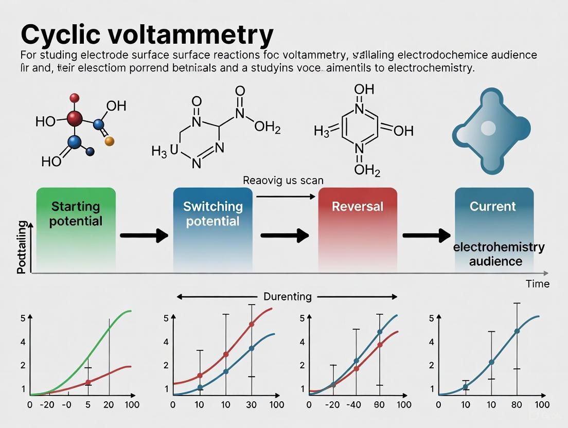
This article provides a comprehensive exploration of cyclic voltammetry (CV) as a powerful diagnostic tool for investigating electrode surface reactions.
Cyclic Voltammetry for Electrode Surface Reactions: A Comprehensive Guide from Fundamentals to Advanced Applications
Abstract
This article provides a comprehensive exploration of cyclic voltammetry (CV) as a powerful diagnostic tool for investigating electrode surface reactions. Tailored for researchers, scientists, and drug development professionals, it covers foundational principles, including redox reversibility and the Randles-Ševčík equation. It then details methodological applications from sensor development to antioxidant capacity assessment, offers practical troubleshooting for common experimental issues, and discusses validation protocols and comparative analyses with other techniques. By integrating foundational knowledge with advanced applications, this guide serves as a vital resource for leveraging CV in electrochemical research and pharmaceutical analysis.
Understanding the Fundamentals: How Cyclic Voltammetry Probes Electrode Surfaces
Cyclic Voltammetry (CV) is a powerful and widely used electrochemical technique that investigates the redox properties of chemical species at an electrode interface [1]. Its power lies in its ability to provide direct insight into the energetics of redox reactions, the dynamics and reversibility of electron transfer, and the rates of coupled chemical reactions [1]. The technique involves scanning the potential applied to a working electrode using a triangular waveform and monitoring the resulting current flow [1]. This current response acts as a rich source of information, yielding voltammograms that are unique to the system under study. CV finds applications across a diverse range of fields, from elucidating complex reaction mechanisms to quantifying key environmental, industrial, and medical analytes [1]. In the context of electrode surface reactions research, it serves as a fundamental tool for characterizing material stability, catalytic activity, and reaction kinetics.
The Triangular Waveform: Principle and Mechanism
The core of the cyclic voltammetry experiment is the application of a triangular potential waveform to the working electrode. In this waveform, the potential is swept linearly with time between two predefined limits, known as vertex potentials [2] [3].
Waveform Generation and Scanning
The potential sweep is described by simple linear equations. During the forward scan, the potential (E) at a given time (t) is defined by: E = E~i~ - vt (for a scan in the negative direction) or E = E~i~ + vt (for a scan in the positive direction) [4] [5]. Here, E~i~ is the initial potential, and v is the scan rate (in V/s). Upon reaching the first vertex potential (E~s~ or Scan Limit 1), the direction of the potential sweep is reversed. The reverse scan follows a similar linear relationship, typically described by E = E~s~ - vt or E = E~s~ + vt until the final potential is reached, which is often, but not always, the same as the initial potential [2] [4]. The timescale of the experiment is systematically controlled by varying the scan rate (v), which allows the investigation of processes with different reaction kinetics [1].
Visualization of the Applied Waveform
The following diagram illustrates the fundamental triangular waveform applied to the working electrode during a cyclic voltammetry experiment.
Interpreting the Current Response
The resulting current is plotted against the applied potential to produce a cyclic voltammogram. The current response is a complex signal composed of two main components: the faradaic current, which is due to the reduction and oxidation (redox) of analyte molecules at the electrode surface, and the non-faradaic current (or capacitive current), which is associated with charging and discharging of the electrode-electrolyte interface (the double layer) [1] [6].
The "Duck-Shaped" Voltammogram
For a simple, reversible, one-electron transfer reaction, the cyclic voltammogram takes on a characteristic "duck-shaped" profile [3] [6]. Key features and their interpretations are summarized in the table below.
Table 1: Key Features of a Cyclic Voltammogram for a Reversible System
| Feature | Symbol | Description | Information Content |
|---|---|---|---|
| Anodic Peak Current | i~p,a~ | Maximum current during the oxidation (reverse) scan [4]. | Proportional to the concentration of the reduced species at the electrode surface [7]. |
| Cathodic Peak Current | i~p,c~ | Maximum current during the reduction (forward) scan [4]. | Proportional to the concentration of the oxidized species at the electrode surface [7]. |
| Anodic Peak Potential | E~p,a~ | Potential at which the anodic peak current is observed [4]. | Related to the energy required for oxidation [1]. |
| Cathodic Peak Potential | E~p,c~ | Potential at which the cathodic peak current is observed [4]. | Related to the energy required for reduction [1]. |
| Formal Redox Potential | E°' | The average of the anodic and cathodic peak potentials: (E~p,a~ + E~p,c~)/2 [7]. | Approximates the standard reduction potential under experimental conditions [4]. |
| Peak Potential Separation | ΔE~p~ | The difference between the anodic and cathodic peak potentials: |E~p,a~ - E~p,c~| [8]. | Diagnostic for reversibility: For a reversible, one-electron transfer, ΔE~p~ is approximately 59 mV at 25°C [1] [5]. |
Assessing Electrochemical Reversibility
The value of ΔE~p~ is a critical parameter for diagnosing the nature of the electron transfer process [5]:
- Reversible System: ΔE~p~ is close to 59/n mV (where n is the number of electrons transferred) and is independent of scan rate. The peak current ratio (i~p,a~/i~p,c~) is approximately 1 [1] [7].
- Quasi-Reversible System: ΔE~p~ is greater than 59/n mV and increases with increasing scan rate. The peak shapes may be broadened [5].
- Irreversible System: Only one peak (either anodic or cathodic) is observed because the reverse electron transfer is too slow to occur on the experimental timescale [1].
Key Quantitative Relationships
The analysis of cyclic voltammetry data relies on several fundamental equations that connect the observed current response to thermodynamic and kinetic parameters.
Foundational Equations
Nernst Equation: Describes the relationship between electrode potential and the concentration of redox species at the electrode surface at equilibrium [1] [3]. E = E°' + (RT/nF) * ln (C~ox~/C~red~) where E°' is the formal potential, R is the gas constant, T is temperature, n is the number of electrons, F is Faraday's constant, and C~ox~ and C~red~ are the surface concentrations of the oxidized and reduced species [3].
Butler-Volmer Equation: Describes the kinetics of the electron transfer reaction, relating the current density (i) to the overpotential (η = E - E°') [3]. i = i~0~ [ exp( (1-α)nFη/RT ) - exp( -αnFη/RT ) ] where i~0~ is the exchange current density and α is the charge transfer coefficient [3].
The Randles-Ševčík Equation
This equation is paramount for quantitative analysis in CV, particularly for reversible, diffusion-controlled systems. It relates the peak current (i~p~) to the concentration of the electroactive species and the scan rate [7] [6]. At 298 K (25°C), the equation is: i~p~ = (2.69 × 10^5) n^3/2 A D^1/2 C v^1/2 where:
- i~p~ = peak current (A)
- n = number of electrons transferred
- A = electrode area (cm²)
- D = diffusion coefficient (cm²/s)
- C = bulk concentration (mol/cm³)
- v = scan rate (V/s)
The direct proportionality between i~p~ and v^1/2 is a hallmark of a diffusion-controlled process [8]. A plot of i~p~ vs. v^1/2 should yield a straight line, and the diffusion coefficient (D) can be calculated from its slope [8].
Experimental Protocols
This section provides a detailed methodology for a standard cyclic voltammetry experiment aimed at characterizing a redox couple, including the study of electron transfer kinetics via variable scan rate measurements.
Research Reagent Solutions and Materials
Table 2: Essential Materials and Reagents for a CV Experiment
| Item | Function / Explanation |
|---|---|
| Potentiostat | Instrument used to apply the potential waveform and measure the resulting current with high precision [3]. |
| Electrochemical Cell | Container for the electrolyte solution and electrodes; can be a dedicated glass cell or a vial [3]. |
| Working Electrode | The electrode where the redox reaction of interest occurs (e.g., glassy carbon, platinum, gold). Its surface must be clean and well-polished [3]. |
| Reference Electrode | Provides a stable, known reference potential against which the working electrode potential is measured (e.g., Ag/AgCl, saturated calomel electrode) [3]. |
| Counter Electrode (Auxiliary) | Completes the electrical circuit, allowing current to flow without passing significant current through the reference electrode (typically a platinum wire or coil) [3]. |
| Supporting Electrolyte | An inert salt (e.g., KCl, TBAPF~6~) at high concentration (typically 0.1-1.0 M) to carry current and minimize resistive losses (iR drop) in solution [3]. |
| Analyte | The redox-active species of interest, dissolved in the electrolyte solution at a known concentration [3]. |
| Solvent | A purified solvent suitable for the electrochemical window being studied (e.g., acetonitrile, water, DMF) [3]. |
Step-by-Step Procedure
Solution Preparation: Prepare a solution containing the supporting electrolyte (e.g., 0.1 M KCl) and the analyte (e.g., 1.0 mM potassium ferricyanide, K~3~[Fe(CN)~6~]) in an appropriate solvent (e.g., water). The solution should be degassed with an inert gas (N~2~ or Ar) for ~10-15 minutes to remove dissolved oxygen, which can interfere as an electroactive species.
Electrode Preparation: Polish the working electrode (e.g., a 3 mm diameter glassy carbon electrode) sequentially with finer grades of alumina slurry (e.g., 1.0 µm, 0.3 µm, and 0.05 µm) on a microcloth pad. Rinse thoroughly with purified water (or solvent) between each polishing step and after the final polish to remove all alumina residues. Sonication for 1-2 minutes in the solvent is also recommended.
Cell Assembly: Place the electrochemical cell in a Faraday cage if available. Insert the clean working electrode, reference electrode, and counter electrode into the solution. Ensure the reference electrode is placed close to the working electrode to minimize iR drop.
Instrument Setup and Data Acquisition:
- Initialization: Allow the system to stabilize; a "quiet time" of 5-60 seconds with no applied potential is often used to establish a stable initial state [5].
- Parameter Configuration: In the potentiostat software, configure the CV parameters:
- Initial/Final E: e.g., 0.6 V (vs. Ag/AgCl)
- Vertex E~1~: e.g., -0.2 V
- Vertex E~2~: (Often set equal to Initial E for a classic triangle waveform) [2]
- Scan Rate (v): Begin with a moderate rate, e.g., 0.1 V/s.
- Number of Cycles: 3-5 cycles to ensure a stable response.
- Run Experiment: Initiate the potential sweep. The potentiostat will apply the triangular waveform and record the current.
Variable Scan Rate Kinetics Study:
Data Analysis:
- For each voltammogram, measure the anodic and cathodic peak currents (i~p,a~, i~p,c~) and peak potentials (E~p,a~, E~p,c~).
- Calculate ΔE~p~ and the formal potential E°' for each scan rate.
- For the variable scan rate data, plot the peak current (i~p~) against the square root of the scan rate (v^1/2). A linear relationship confirms a diffusion-controlled process. Use the slope of this plot with the Randles-Ševčík equation to calculate the diffusion coefficient (D) of the analyte.
Experimental Workflow Visualization
The entire experimental and analytical process is summarized in the workflow below.
Cyclic Voltammetry (CV) is a powerful and ubiquitous electrochemical technique used to investigate the mechanisms of electrode surface reactions. In a CV experiment, the potential of a working electrode is swept linearly between set limits and then swept back, while the resulting current is measured. The plot of this current against the applied potential is called a voltammogram, a rich source of information on the thermodynamics and kinetics of redox processes [4] [9]. For researchers in fields from drug development to energy storage, deciphering the voltammogram is essential for characterizing redox-active molecules, understanding reaction pathways, and evaluating catalytic performance. This note details the quantitative analysis of voltammetric peaks and provides protocols for reliable experimental measurement, framing them within advanced research on electrode surface reactions.
The fundamental shape of a cyclic voltammogram for a reversible, diffusion-controlled system is characterized by a "duck-shaped" profile with distinct forward and reverse peaks [4] [10]. The forward scan, for instance in a negative direction, can reduce an analyte, generating a cathodic peak current (ipc) at the cathodic peak potential (Epc). Upon reversing the scan direction, the newly generated product is re-oxidized, producing an anodic peak current (ipa) at the anodic peak potential (Epa) [4]. The positions, separations, and magnitudes of these peaks form the basis of quantitative analysis.
Quantitative Analysis of Voltammetric Peaks
The key to decoding a voltammogram lies in the precise measurement of its peak attributes. The relationships between these parameters define the nature of the redox system under investigation.
Peak Currents and the Randles-Ševčík Equation
For a reversible system controlled by diffusion, the peak current is quantitatively described by the Randles-Ševčík equation. This relationship is critical for determining concentrations or diffusion coefficients [9]. At 25 °C, the equation is:
i_p = (2.69 × 10^5) n^(3/2) A C D^(1/2) ν^(1/2) [9]
Where:
- i_p = peak current (Amperes)
- n = number of electrons transferred per molecule
- A = electrode surface area (cm²)
- C = concentration of the analyte (mol cm⁻³)
- D = diffusion coefficient (cm² s⁻¹)
- ν = scan rate (V s⁻¹)
A key diagnostic for a reversible system is that the peak current function (i_p / ν^(1/2)) remains constant with changing scan rate [10].
Peak Potentials and Diagnostic Criteria
The potentials at which the current peaks occur provide insights into the thermodynamics and reversibility of the redox reaction.
Table 1: Diagnostic Peak Potential Parameters for Reversible Redox Systems
| Parameter | Definition | Theoretical Value for a Reversible (Nernstian) System |
|---|---|---|
| Peak Potential Separation (ΔE_p) | ΔEp = Epa - E_pc | 59.2 / n mV at 25 °C [10] |
| Formal Reduction Potential (E°') | E°' = (Epa + Epc) / 2 | Equal to the standard potential E^0_{ox/red} [4] [10] |
| Peak Current Ratio | ipa / ipc | 1 at all scan rates [10] |
Deviations from these ideal values indicate non-ideal behavior. A peak separation greater than 59/n mV suggests slow electron transfer kinetics (a quasi-reversible system) or the presence of uncompensated solution resistance [10]. A peak current ratio of less than one often signals that the reduced (or oxidized) species is consumed by a following chemical reaction, making it unavailable for re-oxidation (or re-reduction) on the return scan [10].
Experimental Protocols for Cyclic Voltammetry
A robust experimental protocol is fundamental to obtaining high-quality, interpretable voltammetric data.
The Scientist's Toolkit: Essential Research Reagents and Materials
Table 2: Key Research Reagent Solutions and Materials for CV Experiments
| Item | Function / Explanation |
|---|---|
| Working Electrode | The electrode at which the reaction of interest occurs. Common materials include glassy carbon, platinum, and gold. Its surface must be meticulously cleaned and polished before experiments. |
| Reference Electrode | Provides a stable, fixed potential against which the working electrode potential is measured (e.g., Ag/AgCl, Saturated Calomel Electrode (SCE), or Standard Hydrogen Electrode (SHE)). |
| Counter Electrode (Auxiliary Electrode) | Completes the electrical circuit, often a platinum wire or coil, ensuring current does not pass through the reference electrode. |
| Supporting Electrolyte | A high-concentration, electroinactive salt (e.g., LiClO₄, KCl, TBAPF₆) dissolved in the solvent. Its primary function is to carry current and minimize resistive effects (iR drop). |
| Solvent | The medium for the analyte and electrolyte. Must be purified and electrochemically inert within the potential window of interest (e.g., acetonitrile, water, propylene carbonate). |
| Faradaic and Non-Faradaic Currents | The measured current is a sum of the Faradaic current (from redox events) and the non-Faradaic charging current (from double-layer capacitance, ~νC_dl). The charging current places a lower limit on detection (~10⁻⁵ M) [10]. |
Step-by-Step Workflow for a Basic CV Experiment
The following workflow outlines a standard procedure for acquiring a cyclic voltammogram, from cell preparation to data acquisition. The logical flow of the experiment, from setup to interpretation, is visualized in Figure 1.
Figure 1: Experimental workflow for a cyclic voltammetry experiment, highlighting key preparation and analysis steps.
- Electrode Preparation: Polish the working electrode (e.g., a glassy carbon electrode) successively with finer alumina slurries (e.g., 1.0, 0.3, and 0.05 µm) on a microcloth pad. Sonicate the electrode in deionized water and then in pure solvent for 1-2 minutes each to remove any adhering polishing material [10] [11].
- Cell Assembly: Place the supporting electrolyte and analyte into the electrochemical cell. Insert the three electrodes: the freshly polished working electrode, a clean counter electrode, and the appropriate reference electrode. Ensure the reference electrode is in a stable condition and has a valid filling solution.
- Solution Degassing: Sparge the solution with an inert gas (e.g., nitrogen or argon) for 10-20 minutes to remove dissolved oxygen, which can interfere with the redox chemistry of the analyte.
- Parameter Configuration: In the potentiostat software, set the CV parameters [9]:
- Initial Potential: The starting voltage.
- Vertex Potential(s): The potential where the scan direction reverses.
- Final Potential: The potential where the experiment ends.
- Scan Rate (ν): The rate of potential change (e.g., V/s or mV/s).
- Segments: Typically 2 for a single cycle.
- Data Acquisition: Initiate the experiment. The potentiostat will apply the potential waveform and measure the current. Maintain an inert gas blanket over the solution during the run to prevent oxygen from re-entering.
- Post-Experiment Analysis: Use the software's analysis tools to measure the peak currents (ipa, ipc) and peak potentials (Epa, Epc). Calculate the peak separation (ΔE_p), formal potential (E°'), and peak current ratio to diagnose system reversibility [10].
Advanced Applications and Theoretical Modeling
The interpretation of voltammograms extends beyond simple reversible systems. Advanced applications involve complex coupling of electron transfer with chemical reactions (EC mechanisms) and the use of computational chemistry to bridge theory and experiment.
Diagnosing Irreversibility and Coupled Chemical Reactions
A reversible voltammogram requires fast electron transfer kinetics and chemical stability of the redox species during the experiment. Irreversibility can arise from two major causes [10]:
- Slow Electron Transfer Kinetics: If the heterogeneous electron transfer rate constant (ks) is too small relative to the scan rate, the peak separation ΔEp will exceed 59/n mV and will increase with increasing scan rate. This characterizes a quasi-reversible system.
- Following Chemical Reactions: If the product of the electron transfer (e.g., 'R' from the reduction of 'O') is consumed by a subsequent chemical reaction (e.g., R → P), the system becomes chemically irreversible. This is diagnosed by a peak current ratio (ipa/ipc) of less than 1, as only a fraction of 'R' remains to be re-oxidized [10]. The effect of the chemical reaction depends on the ratio of its rate constant (k) to the scan rate (ν).
Bridging Theory and Experiment with Computational Chemistry
Modern research leverages computational models, particularly Density Functional Theory (DFT), to gain atomic-level insight into electrochemical reactions. The calculated change in Gibbs free energy (ΔG) for a redox reaction can be directly correlated to the experimental redox potential via the Nernst equation [12]. This allows for the prediction and interpretation of voltammetric behavior.
A powerful framework for modeling complex reactions involving both proton and electron transfers is the "Scheme of Squares" [12]. This scheme diagrams possible pathways involving decoupled electron transfer (ET) and proton transfer (PT), or a coupled proton-electron transfer (PET). By calibrating DFT-calculated redox potentials against experimental CV data, researchers can enhance the predictive accuracy of their models and illuminate detailed redox mechanisms that are challenging to probe by experiment alone [12]. This synergy between computation and CV is proving invaluable across applications from energy storage to drug development.
Electrochemical reversibility is a fundamental concept in electrochemistry, providing critical insights into the kinetics and mechanisms of electrode reactions. Within the context of cyclic voltammetry (CV) for electrode surface reactions research, reversibility characterizes the electron transfer rate between an electrode and solution species [13]. This classification is crucial for researchers and drug development professionals who utilize CV to study redox-active molecules, electrocatalysts, and biological systems. The term "reversible" in electrochemistry does not refer to the chemical stability of redox products but specifically describes the kinetic facility of electron transfer [13] [14]. A chemically reversible system may still be electrochemically irreversible if electron transfer kinetics are slow, highlighting the importance of distinguishing between these concepts [14] [15].
Understanding electrochemical reversibility enables researchers to extract quantitative kinetic parameters, assess reaction mechanisms, and design improved electrochemical systems. For drug development, these principles help characterize redox properties of pharmaceutical compounds, understand metabolic pathways, and develop electrochemical sensors [16] [17]. This application note provides a comprehensive framework for classifying, diagnosing, and investigating electrochemical reversibility using cyclic voltammetry, with specific protocols for experimental design and data interpretation.
Theoretical Foundations
Defining Reversibility in Electrochemical Systems
Electchemical reversibility encompasses three distinct but interrelated concepts: chemical reversibility, electrochemical reversibility, and practical reversibility [15].
Chemical reversibility refers to the stability of electrogenerated species and their ability to return to the original reactant during a reverse potential scan. A system is chemically reversible when the product of the electrochemical reaction does not undergo subsequent chemical transformations that prevent its reconversion to the starting material [14] [15]. For the EC mechanism: [ O + e^- \rightleftarrows R \xrightarrow{k_c} Z ] chemical irreversibility occurs when the chemical step ((R \rightarrow Z)) dominates over the backward electrochemical step ((R \rightarrow O)) [15].
Electrochemical reversibility describes the rate of electron transfer relative to mass transport. It is formally defined by the ratio of charge transfer rate to mass transfer rate, quantified by the parameter (\Lambda) [15]: [ \Lambda = \frac{k^0}{(D f \nu)^{0.5}} ] where (k^0) is the standard heterogeneous rate constant (cm/s), (D) is the diffusion coefficient (cm²/s), (f = F/RT) (V⁻¹), and (\nu) is the scan rate (V/s) [15].
Practical reversibility refers to the cycleability of a system, often relevant to battery materials and electrochemical devices, where a system may function effectively even under electrochemically irreversible conditions [15].
Key Kinetic Parameters
The behavior of electrochemical systems is governed by several key parameters:
- Standard heterogeneous rate constant ((k^0)): Quantifies the intrinsic kinetic facility of a redox couple. Values ≥1 cm/s indicate fast electron transfer, while values ≤10⁻⁵ cm/s suggest sluggish kinetics [15].
- Charge transfer coefficient ((\alpha)): Describes the symmetry of the energy barrier for electron transfer, typically ranging from 0 to 1 [15].
- Dimensionless kinetic parameter ((kc tk)): For EC mechanisms, this determines the extent of chemical irreversibility, where (kc) is the chemical rate constant and (tk) is the experimental timescale [15].
Classification and Diagnostic Criteria
System Classification Based on CV Response
Electrochemical systems are categorized into three distinct regimes based on their cyclic voltammetric behavior. The table below summarizes the key diagnostic parameters for each classification:
Table 1: Diagnostic Criteria for Electrochemical Reversibility in Cyclic Voltammetry
| Parameter | Reversible | Quasi-Reversible | Irreversible |
|---|---|---|---|
| Electron Transfer Kinetics | Fast relative to mass transfer | Intermediate | Slow relative to mass transfer |
| (\Lambda) Value | (\Lambda \geq 15) [15] | (15 \geq \Lambda \geq 10^{-2(1+\alpha)}) [15] | (\Lambda \leq 10^{-2(1+\alpha)}) [15] |
| Peak Separation ((\Delta E_p)) | (\approx \frac{59}{n} mV) at 25°C [10] | > (\frac{59}{n} mV), increases with scan rate [10] | — |
| Peak Current Ratio ((i{pa}/i{pc})) | (\approx 1) [10] | (\approx 1) (but broader peaks) | — |
| Peak Potential Shift with Scan Rate | Constant [18] | Shifts with scan rate | Linear shift with log(scan rate) |
| (k^0) Range (cm/s) | > 0.020 [15] | 0.02 > (k^0) > 5×10⁻⁵ [15] | < 5×10⁻⁵ [15] |
| Rate-Limiting Step | Mass transport | Mixed: electron and mass transfer | Electron transfer |
The following decision pathway provides a systematic approach for classifying electrochemical systems based on cyclic voltammetry data:
Electrochemical System Classification Pathway
Advanced Diagnostic Parameters
For more detailed analysis, researchers should consider these additional parameters:
Table 2: Advanced Diagnostic Parameters for Reversibility Assessment
| Parameter | Definition | Diagnostic Utility |
|---|---|---|
| Peak Current Function ((i_p/\nu^{1/2})) | ( \frac{i_p}{\nu^{1/2}} = 2.69 \times 10^5 n^{3/2} A C D^{1/2} ) [10] | Constant for reversible systems; varies for irreversible processes |
| Half-Peak Potential ((E_{p/2})) | Potential at half the peak current | Used with Tafel analysis for irreversible systems |
| Capacitive Current Contribution | ( ic = \nu C{dl} ) [10] | Affects detection limit and data interpretation at high scan rates |
| Chemical Rate Constant ((k_c)) | Rate of follow-up chemical reaction | Determines extent of chemical irreversibility in EC mechanisms |
Experimental Protocols
Standard Cyclic Voltammetry Protocol for Reversibility Assessment
This protocol provides a standardized methodology for collecting cyclic voltammetry data to assess electrochemical reversibility, specifically optimized for electrode surface reactions research.
Research Reagent Solutions and Materials
Table 3: Essential Research Reagents and Materials
| Item | Specification | Function/Purpose |
|---|---|---|
| Working Electrode | Glassy carbon (1-3 mm diameter), polished to mirror finish | Primary reaction surface for electron transfer |
| Reference Electrode | Ag/AgCl or saturated calomel (SCE) | Stable potential reference |
| Counter Electrode | Platinum wire or mesh | Completes electrical circuit |
| Supporting Electrolyte | 0.1 M TBAPF₆, TBABF₄, or LiClO₄ in appropriate solvent | Provides ionic conductivity minimizes ohmic drop |
| Solvent System | Anhydrous acetonitrile, DMF, or aqueous buffers | Dissolves analyte without interfering reactions |
| Redox Probe | 1-3 mM Ferrocene (Fc/Fc⁺) or other internal standard | Validation of experimental setup |
| Analyte Solution | 1-5 mM in electrolyte solution | Target molecule for reversibility assessment |
| Polishing Supplies | Alumina slurry (0.3, 0.05 μm) or diamond polish | Maintains reproducible electrode surface |
Step-by-Step Procedure
Electrode Preparation
- Polish working electrode sequentially with 0.3 μm and 0.05 μm alumina slurry on microcloth
- Sonicate in deionized water for 2 minutes to remove polishing residues
- Rinse thoroughly with solvent system (water for aqueous, acetone for non-aqueous)
- Dry under gentle stream of nitrogen or argon gas
Solution Preparation and Degassing
- Prepare supporting electrolyte solution at precisely 0.1 M concentration
- Dissolve analyte to final concentration of 1-5 mM
- Transfer 10-20 mL to electrochemical cell
- Sparge with inert gas (N₂ or Ar) for 10-15 minutes to remove oxygen
- Maintain inert atmosphere blanket during measurements
Instrumentation and Parameters
- Setup potentiostat with standard three-electrode configuration
- Verify connections: working (green), reference (white), counter (red)
- Set initial parameters:
- Initial potential: +0.5 V (for reductions) or -0.5 V (for oxidations) vs. formal potential
- Switching potential: Determined from preliminary scans
- Scan rates: 0.01, 0.05, 0.1, 0.2, 0.5, 1.0 V/s
- Sensitivity: Auto-ranging or appropriate manual range
Data Collection Workflow
- Begin with redox probe (e.g., 1 mM ferrocene) to validate system
- Record CV at multiple scan rates (minimum 5 different rates)
- Repeat for analyte solution across same scan rates
- Between measurements, polish electrode and repeat cleaning protocol
- Maintain constant temperature (±1°C) throughout experiment
The following workflow illustrates the complete experimental procedure:
Experimental Workflow for Reversibility Assessment
Data Analysis and Interpretation Protocol
Peak Parameter Measurement
- Identify anodic peak potential ((E{pa})) and cathodic peak potential ((E{pc}))
- Measure corresponding peak currents ((i{pa}), (i{pc}))
- Calculate (\Delta Ep = E{pa} - E_{pc})
- Determine peak current ratio (i{pa}/i{pc})
Scan Rate Dependence Analysis
- Plot (i_p) vs. (\nu^{1/2}) for reversible system diagnosis
- Plot (E_p) vs. log((\nu)) for irreversible systems
- Calculate peak current function ((i_p/\nu^{1/2})) for each scan rate
- Note changes in (\Delta E_p) with increasing scan rate
Kinetic Parameter Extraction
- For quasi-reversible systems: extract (k^0) from (\Delta E_p) vs. (\nu) plot
- For EC mechanisms: determine (kc) from (i{pa}/i_{pc}) vs. (\nu) dependence
- Use Nicholson method for quasi-reversible systems: (k^0 = \psi (\pi D n F \nu /RT)^{1/2})
Advanced Applications and Case Studies
Investigating Copper Complexes in Atom Transfer Radical Addition
In a seminal study, Matyjaszewski and Amatore investigated the relationship between redox potential of Cu(I) complexes and their behavior as co-initiators in atom transfer radical addition (ATRA) and polymerization (ATRP) reactions [16]. They studied eight ligands with two copper salts (CuCl and CuBr), many exhibiting sluggish outer-sphere electron transfer rates evident from non-Nernstian peak separations in cyclic voltammograms [16]. Despite the electrochemical quasi-reversibility, approximated redox potentials (E₁/₂) correlated with apparent polymerization rates, demonstrating that more reducing Cu(I) complexes (associated with less oxidizing Cu(II) complexes) facilitated more rapid reactions [16]. This case illustrates how electrochemical reversibility analysis provides insights into catalytic behavior even for non-ideal systems.
Experimental Considerations for Organometallic Complexes:
- Use rigorously anhydrous, oxygen-free conditions
- Prefer non-coordinating solvents (e.g., CH₂Cl₂) with TBAPF₆ electrolyte
- Account for adsorption effects which may complicate interpretation
- Consider temperature control for improved electrochemical response
Electrochemical Glycosylation with Chalcogenoglycosides
Yoshida and Yamago demonstrated electrochemical glycosylation using chalcogenoglycosides as glycosyl-transfer agents, employing linear sweep voltammetry to measure irreversible, one-electron oxidation potentials [16]. The oxidation potentials showed clear trends with ionization potential of chalcogen atoms (Te < Se < S), indicating molecular orbital localization on chalcogen atoms [16]. These distinguishable oxidation potentials enabled selective activation of specific chalcogenoglycosides toward oxidation-induced glycosyl transfer, showcasing how irreversible electrochemical responses can be exploited synthetically [16].
Protocol for Chemical Reversibility Assessment in EC Mechanisms
For systems with coupled chemical steps, use this specialized protocol:
Multi-Scan Rate Analysis
- Collect CV data across wide scan rate range (0.01-10 V/s if possible)
- Plot (i{pa}/i{pc}) vs. scan rate
- Calculate dimensionless parameter (kc tk) where (tk = 2(Vi - V_f)/\nu)
Digital Simulation
- Use software such as EC-Lab CV Sim or DigiElch
- Fit experimental data by varying (k^0), (\alpha), and (k_c)
- Iterate until satisfactory agreement with experimental voltammograms
Double Potential Step Chronoamperometry
- Apply forward potential step to generate R
- Step back to oxidize remaining R
- Compare forward and backward charge to quantify chemical loss
- Use Cottrell equation analysis: (I_t = 3.03 × 10^5 n A D^{1/2} C t^{-1/2}) [16]
Troubleshooting and Method Validation
Common Experimental Artifacts and Solutions
Table 4: Troubleshooting Guide for Reversibility Assessment
| Problem | Potential Causes | Solutions |
|---|---|---|
| Increasing (\Delta E_p) with scan rate | Uncompensated resistance [10] | Use positive feedback IR compensation; reduce analyte concentration; use smaller electrode |
| Poor reproducibility between scans | Electrode fouling or passivation | Implement rigorous cleaning protocol; use fresh surface for each measurement |
| Non-linear (i_p) vs. (\nu^{1/2}) plot | Adsorption effects or chemical complications | Vary concentration to identify adsorption; check for follow-up chemistry |
| Missing return peak | Chemical irreversibility or slow electron transfer | Increase scan rate; check for decomposition products; verify switching potential |
| Asymmetric peak shapes | Heterogeneous electrode surface | Improve polishing protocol; consider electrode replacement |
Validation Methods for Reversibility Classification
Internal Standard Method
- Add known reversible couple (ferrocene/ferrocenium) to analyte solution
- Compare peak separation and shape directly
- Normalize potentials to internal reference
Mass Transport Verification
- Use rotating disk electrode to control convection
- Compare stationary and hydrodynamic voltammetry
- Confirm diffusion control in quiescent solution
Computational Validation
Electrochemical reversibility classification provides fundamental insights into electron transfer kinetics and reaction mechanisms critical for electrode surface reactions research. The protocols and methodologies presented herein enable researchers to systematically characterize redox systems, distinguish between chemical and electrochemical reversibility, and extract meaningful kinetic parameters. For drug development professionals, these approaches facilitate understanding of redox metabolism, electrochemical sensor development, and characterization of redox-active pharmaceuticals. Proper application of these principles requires careful attention to experimental detail, appropriate data interpretation, and awareness of potential artifacts that may complicate reversibility assessment. Through standardized implementation of these protocols, researchers can generate reliable, reproducible electrochemical data that advances understanding of electrode processes and supports development of improved electrochemical technologies.
The Nernst Equation and Its Role in Surface Concentration Profiles
The Nernst equation provides the fundamental relationship between the electrochemical potential of an electrode and the activities (or concentrations) of redox-active species in solution, serving as a cornerstone for understanding and interpreting electrode surface reactions [19] [20]. This equation becomes particularly critical when studying interfacial processes using techniques like cyclic voltammetry (CV), as it directly governs the surface concentration profiles of electroactive species that develop adjacent to the electrode surface during experimentation [4] [21]. For researchers investigating electrochemical mechanisms in drug development, understanding how the Nernst equation dictates the ratio of oxidized to reduced species at the electrode interface is essential for predicting reaction behavior, optimizing experimental conditions, and interpreting the resulting voltammetric data [21] [3].
The generalized form of the Nernst equation for a reduction reaction is expressed as:
[E = E^0 - \frac{RT}{nF} \ln \frac{a{\text{Red}}}{a{\text{Ox}}} ]
where (E) is the electrode potential, (E^0) is the standard electrode potential, (R) is the universal gas constant, (T) is temperature, (n) is the number of electrons transferred, (F) is Faraday's constant, and (a{\text{Red}}) and (a{\text{Ox}}) represent the activities of the reduced and oxidized species, respectively [20]. In practice, for dilute solutions where activity coefficients approach unity, concentrations are commonly substituted for activities, giving rise to the formal potential (E^{0'}) that encompasses medium effects [20] [22].
Theoretical Foundation: Linking the Nernst Equation to Surface Concentrations
Fundamental Principles and Mathematical Formalism
The Nernst equation establishes that at any applied potential, a specific ratio of reduced to oxidized species will be maintained at the electrode surface to satisfy thermodynamic equilibrium [19] [20]. This relationship is quantitatively described by:
[E = E^{0'} - \frac{RT}{nF} \ln \frac{C{\text{Red}}(0,t)}{C{\text{Ox}}(0,t)} ]
where (C{\text{Red}}(0,t)) and (C{\text{Ox}}(0,t)) represent the surface concentrations of reduced and oxidized species respectively at time (t) [20] [3]. This expression highlights the direct correlation between the applied potential (E) and the concentration ratio at the electrode-solution interface.
At a temperature of 25°C (298 K), the Nernst equation simplifies to:
[E = E^{0'} - \frac{0.0592}{n} \log{10} \frac{C{\text{Red}}(0,t)}{C_{\text{Ox}}(0,t)} ]
This simplified form is particularly useful for rapid calculations during experimental design and data analysis [19] [23].
Table 1: Nernst Equation Forms and Applications
| Form | Equation | Application Context |
|---|---|---|
| General Form | (E = E^{0'} - \frac{RT}{nF} \ln \frac{C{\text{Red}}}{C{\text{Ox}}}) | Fundamental thermodynamic relationship |
| 25°C Simplified | (E = E^{0'} - \frac{0.0592}{n} \log{10} \frac{C{\text{Red}}}{C_{\text{Ox}}}) | Room temperature experiments |
| Formal Potential | (E^{0'} = E^{0} - \frac{RT}{nF} \ln \frac{\gamma{\text{Red}}}{\gamma{\text{Ox}}}) | Accounting for activity coefficients |
Development of Concentration Gradients at the Electrode Interface
When the electrode potential is perturbed from equilibrium (as occurs in cyclic voltammetry), the Nernst equation demands an instantaneous adjustment of the surface concentration ratio to maintain the prescribed relationship [4]. This adjustment occurs via electron transfer reactions that convert Ox to Red or vice versa, thereby establishing concentration gradients that extend from the electrode surface into the bulk solution [4] [3]. These gradients serve as the driving force for diffusion-controlled mass transport, which follows Fick's laws of diffusion:
[\frac{\partial C}{\partial t} = D \frac{\partial^2 C}{\partial x^2} ]
where (D) is the diffusion coefficient and (x) is the distance from the electrode surface [4]. The interplay between the Nernstian boundary condition at the electrode surface and diffusional mass transport in the solution bulk fundamentally shapes the current response measured in cyclic voltammetry experiments [4] [21].
Figure 1: The cyclic relationship between applied potential and current response in CV, governed by the Nernst equation's control over surface concentrations.
Experimental Protocols for Investigating Surface Concentration Effects
Protocol 1: Establishing Nernstian Behavior in Reversible Systems
Purpose: To verify that an electrochemical system exhibits Nernstian behavior and determine its formal potential ((E^{0'})) [4] [18].
Materials and Reagents:
- Electroactive analyte solution (0.5-10 mM) in supporting electrolyte
- Three-electrode system: Working electrode (glassy carbon, Pt, or Au), reference electrode (Ag/AgCl or SCE), counter electrode (Pt wire)
- Deoxygenated solvent with supporting electrolyte (0.1 M Bu₄NPF₆ in acetonitrile or KCl in aqueous systems)
- Potentiostat with cyclic voltammetry capability
Procedure:
- Polish the working electrode sequentially with 1.0, 0.3, and 0.05 μm alumina slurry on a microcloth pad, followed by thorough rinsing with purified solvent [3].
- Transfer the analyte solution to the electrochemical cell and purge with inert gas (N₂ or Ar) for 10-15 minutes to remove dissolved oxygen [3].
- Assemble the three-electrode system ensuring proper immersion and positioning.
- Record cyclic voltammograms at multiple scan rates (typically 10 mV/s to 1 V/s) [18].
- Measure the peak separation ((\Delta Ep = E{pa} - E_{pc})) between anodic and cathodic peaks.
- Calculate the formal potential as (E^{0'} = \frac{E{pa} + E{pc}}{2}) [4].
Data Interpretation:
- A system is considered electrochemically reversible when (\Delta E_p \approx \frac{0.059}{n}) V and peak currents scale with the square root of scan rate [4] [18].
- The half-wave potential ((E_{1/2})) should be independent of scan rate for a Nernstian system [18].
Protocol 2: Quantifying Surface Concentration Profiles via Scan Rate Studies
Purpose: To characterize the diffusion layer thickness and surface concentration evolution as a function of scan rate [4] [21].
Materials and Reagents: (Same as Protocol 1 with emphasis on precise temperature control)
Procedure:
- Prepare electrochemical cell as in Protocol 1 steps 1-3.
- Program the potentiostat to perform CV scans across a wide range of scan rates (0.01 to 10 V/s).
- For each scan rate, record the voltammogram and extract the peak current ((ip)), peak potential ((Ep)), and half-peak potential ((E_{p/2})).
- Plot (i_p) versus (\nu^{1/2}) (where (\nu) is scan rate) to verify diffusion control.
- Calculate the diffusion coefficient using the Randles-Ševčík equation [3]:
[i_p = (2.69 \times 10^5) n^{3/2} A D^{1/2} C \nu^{1/2}]
where (A) is electrode area, (D) is diffusion coefficient, and (C) is bulk concentration.
Data Interpretation:
- Linear relationship between (i_p) and (\nu^{1/2}) indicates diffusion-controlled electron transfer [3].
- The scan rate directly affects the diffusion layer thickness ((\delta)), with higher scan rates producing thinner diffusion layers according to (\delta \approx \sqrt{Dt}), where (t) is the timescale of the experiment [4].
Table 2: Key Parameters for Surface Concentration Analysis in Cyclic Voltammetry
| Parameter | Symbol | Determination Method | Relationship to Surface Concentrations |
|---|---|---|---|
| Formal Potential | (E^{0'}) | ((E{pa} + E{pc})/2) | Center point where [Ox]₀ = [Red]₀ |
| Peak Separation | (\Delta E_p) | (E{pa} - E{pc}) | Indicator of electrochemical reversibility |
| Diffusion Coefficient | (D) | Randles-Ševčík equation | Controls mass transport to electrode |
| Electron Transfer Number | (n) | (Ep - E{p/2} = \frac{0.0565}{n}) | Determines Nernstian slope |
| Scan Rate | (\nu) | Experimental setting | Affects diffusion layer thickness |
Data Analysis and Interpretation in Pharmaceutical Applications
Analyzing Drug Redox Properties and Reaction Mechanisms
For pharmaceutical researchers, cyclic voltammetry provides critical insights into drug redox behavior and metabolic transformation pathways [21]. The Nernst equation enables quantification of formal potentials that correlate with pharmacological activity and toxicity predictions.
Interpretation Framework:
- Reversibility Assessment: Determine if the drug undergoes reversible electron transfer, which suggests possible regenerative metabolism, or irreversible reactions indicating metabolic detoxification pathways [18].
- Formal Potential Mapping: Calculate (E^{0'}) values to predict intracellular redox behavior relative to biological redox couples (e.g., NAD⁺/NADH, glutathione disulfide/glutathione) [24].
- pH Dependence Studies: Investigate proton-coupled electron transfer mechanisms by performing CV across physiological pH ranges, using the modified Nernst equation for proton-dependent systems:
[E = E^{0'} - \frac{0.0592}{n} \log \frac{[Red]}{[Ox]}} - \frac{0.0592 \cdot m}{n} \text{pH}]
where (m) represents the number of protons transferred per electron [24].
Figure 2: Mass transport and electron transfer processes at the electrode interface, with surface concentrations governed by the Nernst equation.
Advanced Applications: Adsorbed Species and Surface-Confined Systems
Many pharmaceutical compounds exhibit surface adsorption on electrode materials, altering their electrochemical behavior from solution-phase diffusion control to surface-confined reactions [21]. For adsorbed species obeying Langmuir isotherms, the current response becomes directly proportional to scan rate rather than its square root:
[i_p = \frac{n^2 F^2}{4RT} \nu A \Gamma ]
where (\Gamma) represents the surface coverage of the adsorbed species [21] [3]. This relationship provides a powerful method for quantifying drug adsorption at simulated biological interfaces.
The Scientist's Toolkit: Essential Reagents and Materials
Table 3: Research Reagent Solutions for Nernst Equation and Surface Profile Studies
| Reagent/Material | Function | Application Notes |
|---|---|---|
| Supporting Electrolytes (TBAP, KCl) | Minimize ohmic drop and control ionic strength | Use at concentrations 50-100x higher than analyte [3] |
| Electrode Polishing Kits | Maintain reproducible electrode surface geometry | Essential for consistent diffusion layer formation [3] |
| Internal Standard Compounds | Reference formal potentials | Ferrocene/ferrocenium (Fc/Fc⁺) commonly used in non-aqueous systems [18] |
| Deoxygenation Systems | Remove dissolved oxygen | Prevents interference from O₂ reduction waves [3] |
| Standard Redox Couples | Validate Nernstian response | Potassium ferricyanide/ferrocyanide for aqueous systems [18] |
The Nernst equation provides the fundamental link between controlled experimental parameters (applied potential) and the resulting surface concentration profiles that govern electrochemical responses in cyclic voltammetry [19] [4]. For researchers in drug development, mastering the interpretation of these relationships enables deeper understanding of redox mechanisms, metabolic pathways, and reactivity predictions [21] [24]. The protocols and analysis methods outlined herein establish a framework for extracting quantitative information about electron transfer kinetics, diffusion characteristics, and adsorption behavior that directly inform pharmaceutical development pipelines.
The Randles-Ševčík equation is a cornerstone of electrochemistry, providing a quantitative relationship between peak current, scan rate, and diffusion in cyclic voltammetry experiments. For researchers investigating electrode surface reactions, this equation is an indispensable tool for distinguishing between diffusion-controlled and adsorption-controlled processes, determining key electrochemical parameters, and validating the reversibility of redox systems. Its development in the mid-20th century by J.E.B. Randles and C.I. Sevcik established a fundamental principle for analyzing voltammetric data, with contemporary applications spanning from energy storage to sensor development [25]. Within the broader context of cyclic voltammetry research, understanding this equation enables scientists to extract critical information about reaction mechanisms, transport properties, and electrode characteristics from simple current-potential measurements.
Theoretical Foundations
The Mathematical Formulation
The Randles-Ševčík equation quantitatively describes the peak current ((i_p)) observed in a cyclic voltammogram for an electrochemically reversible system with soluble reactants and products. The general form of the equation is:
[i_p = 0.4463 \ nFAC \left( \frac{nF \nu D}{RT} \right)^{1/2}]
Where the variables and their units are defined as follows [26]:
- (i_p): peak current (A)
- (n): number of electrons transferred in the redox event
- (F): Faraday constant (96485 C mol⁻¹)
- (A): electrode area (cm²)
- (C): concentration (mol/cm³)
- (\nu): scan rate (V/s)
- (D): diffusion coefficient (cm²/s)
- (R): universal gas constant (8.314 J K⁻¹ mol⁻¹)
- (T): temperature (K)
For practical applications at standard laboratory temperature (25°C), the equation simplifies to [26] [27]:
[i_p = (2.69 \times 10^5) \ n^{3/2} A C D^{1/2} \nu^{1/2}]
The constant (2.69 \times 10^5) has units of C mol⁻¹ V⁻¹/2, and all other variables maintain the units specified above.
Physical Interpretation and Significance
The fundamental relationship described by the Randles-Ševčík equation—that peak current increases with the square root of scan rate—stems from diffusion-limited electrochemical processes. At faster scan rates, the concentration gradient of electroactive species near the electrode surface becomes steeper, resulting in higher flux of species to the electrode and consequently higher measured current [26]. This relationship holds specifically for systems where electron transfer is rapid (electrochemically reversible) and the redox species are freely diffusing rather than adsorbed onto the electrode surface.
The equation's predictive power allows researchers to distinguish between different types of electrochemical processes based on the relationship between peak current and scan rate. A linear plot of (i_p) versus (\nu^{1/2}) with a slope close to the theoretical value indicates a diffusion-controlled reversible system. Deviation from this linearity suggests either electrochemical quasi-reversibility or that electron transfer occurs through surface-adsorbed species rather than freely diffusing ones [28].
Experimental Protocols
Determining Electroactive Area
The electroactive area of an electrode often differs from its geometric area due to surface roughness, porosity, or fouling. The Randles-Ševčík equation provides a method to determine this crucial parameter experimentally.
Protocol: Electroactive Area Calculation
- Select a redox probe: Prepare a solution containing a well-characterized, reversible redox couple with known diffusion coefficient and concentration (e.g., 1-10 mM potassium ferricyanide in 1 M KCl) [25] [29].
- Setup electrochemical cell: Use a three-electrode configuration with the test electrode as working electrode, appropriate reference electrode (e.g., Ag/AgCl), and platinum counter electrode.
- Record cyclic voltammograms: Acquire CV data across multiple scan rates (typically 10-500 mV/s) while maintaining other parameters constant [29].
- Measure peak currents: For each scan rate, accurately measure the peak current from the voltammogram.
- Plot and calculate: Plot (i_p) versus (\nu^{1/2}) and determine the slope of the linear regression.
- Calculate area: Using the known values of (n), (C), and (D), rearrange the Randles-Ševčík equation to solve for (A):
[A = \frac{\text{slope}}{2.69 \times 10^5 \ n^{3/2} C D^{1/2}}]
This protocol is particularly valuable for characterizing modified electrodes, assessing electrode fouling, and quantifying the active area of porous or nanostructured electrodes [25].
Determining Diffusion Coefficient
For novel redox species, the diffusion coefficient is often unknown and can be determined using the Randles-Ševčík equation.
Protocol: Diffusion Coefficient Determination
- Prepare standard electrode: Use an electrode with known electroactive area (e.g., polished glassy carbon electrode).
- Prepare analyte solution: Create a solution with known concentration of the redox species of interest in appropriate supporting electrolyte.
- Record CV data: Acquire cyclic voltammograms at multiple scan rates as in the previous protocol.
- Plot (i_p) vs. (\nu^{1/2}): Establish the linear relationship and determine the slope.
- Calculate diffusion coefficient: Rearrange the Randles-Ševčík equation to solve for (D):
[D = \left( \frac{\text{slope}}{2.69 \times 10^5 \ n^{3/2} A C} \right)^2]
This application is particularly valuable when studying new electroactive molecules, as the diffusion coefficient plays a crucial role in understanding mass transport limitations and optimizing electrochemical systems [25].
Validating Reversibility and Diagnosing Process Type
The relationship between peak current and scan rate provides critical diagnostic information about the nature of the electrochemical process under investigation.
Protocol: Process Diagnosis
- Acquire multi-scan rate data: Collect cyclic voltammograms at a minimum of 5 different scan rates spanning at least an order of magnitude (e.g., 20, 50, 100, 200, 500 mV/s).
- Measure peak currents: Record both anodic and cathodic peak currents for each scan rate.
- Create two diagnostic plots:
- Plot (ip) versus (\nu^{1/2})
- Plot log((ip)) versus log((\nu))
- Analyze plot characteristics:
This diagnostic capability is essential for understanding reaction mechanisms, particularly when working with novel materials or complex electrochemical systems.
Data Presentation and Analysis
Quantitative Relationships
Table 1: Key Parameter Relationships in Randles-Ševčík Analysis
| Parameter Relationship | Mathematical Expression | Diagnostic Interpretation |
|---|---|---|
| Peak current vs. scan rate | (i_p \propto \nu^{1/2}) | Diffusion-controlled process |
| Log peak current vs. log scan rate | Slope ≈ 0.5 | Diffusion-controlled process [30] |
| Log peak current vs. log scan rate | Slope ≈ 1.0 | Adsorption-controlled process [30] |
| Anodic vs. cathodic peak currents | (i{p,a}/i{p,c} ≈ 1) | Reversible electron transfer |
| Peak potential separation | (\Delta E_p ≈ 57/n) mV | Reversible system at 25°C |
Table 2: Experimental Parameters for Randles-Ševčík Applications
| Application | Known Parameters | Unknown Parameter | Key Requirements |
|---|---|---|---|
| Electroactive area determination | (n), (C), (D) | (A) | Reversible redox probe [25] [29] |
| Diffusion coefficient determination | (n), (C), (A) | (D) | Well-defined electrode area [25] |
| Concentration determination | (n), (A), (D) | (C) | Known electrode and diffusion characteristics [25] |
| Reaction diagnostics | None (relative measurements) | Reaction mechanism | Multiple scan rates |
Visualization of Randles-Ševčík Relationships
This workflow illustrates the systematic approach for applying Randles-Ševčík analysis to determine electrochemical parameters and diagnose reaction mechanisms. The pathway begins with experimental data collection and proceeds through diagnostic plotting to final parameter calculation.
The Scientist's Toolkit
Essential Research Reagent Solutions
Table 3: Key Reagents for Randles-Ševčík Experiments
| Reagent/Solution | Typical Composition | Primary Function | Application Notes |
|---|---|---|---|
| Potassium ferricyanide probe | 1-10 mM K₃[Fe(CN)₆] in 1 M KCl | Reversible redox standard for electrode characterization | Well-established D value (~7.6×10⁻⁶ cm²/s) enables accurate area calculation [29] |
| Supporting electrolyte | 0.1 M KCl, KNO₃, or phosphate buffer | Provides ionic conductivity without participating in reactions | Minimizes IR drop; concentration should exceed analyte by 20-100x |
| Ascorbate solution | 10 mM ascorbate in 0.1 M KCl [30] | Model system for demonstrating diffusion control | Freely-diffusing analyte for educational demonstrations |
| Electrode cleaning solution | Alumina slurry (0.3, 0.05 μm) or specific solvents | Maintains reproducible electrode surface | Critical for obtaining consistent electroactive area measurements [31] |
| Redox mediator solutions | Ferrocene/ferrocenium, Ru(NH₃)₆³⁺/²⁺ | Alternative reversible couples | Provides options for different potential windows and conditions |
Advanced Applications and Considerations
Modified Equations for Quasi-Reversible and Irreversible Systems
While the standard Randles-Ševčík equation applies to fully reversible systems, modified versions exist for quasi-reversible and irreversible processes. For quasi-reversible systems where 63 < (n\Delta E_p) < 200 mV, the equation becomes [29]:
[i_p = (2.69 \times 10^5 \ n^{3/2} A D C \nu^{1/2}) \ K(\Lambda,\alpha)]
Where (K(\Lambda,\alpha)) is a dimensionless parameter that accounts for the kinetics of electron transfer. For completely irreversible systems ((n\Delta E_p) > 200 mV), the appropriate form is [29]:
[i_p = (2.99 \times 10^5) \ n \alpha^{1/2} A D^{1/2} C \nu^{1/2}]
Where (\alpha) is the charge transfer coefficient. These modified equations extend the utility of Randles-Ševčík analysis to a broader range of electrochemical systems beyond ideal reversible cases.
Recent Research Applications
Contemporary research continues to leverage the Randles-Ševčík equation across diverse applications. In materials science, it has been used to characterize hierarchical CuO nanorod arrays for electrochemical CO₂ reduction, where the relationship between peak current and scan rate confirmed the diffusion-controlled nature of the process [32]. In electrocatalysis, studies of Ni/Al-carbonate hydrotalcite for methanol oxidation employed Randles-Ševčík principles to distinguish between adsorption-controlled behavior in the non-faradaic region and diffusion-controlled processes during methanol oxidation [31]. Environmental chemistry applications include investigating the redox behavior of mercuric chloride and its interaction with Orange G dye, where scan rate studies provided insights into complexation mechanisms and reaction kinetics [33].
Troubleshooting and Method Validation
Common Experimental Challenges
Several practical issues can compromise Randles-Ševčík analysis. Uncompensated resistance can distort voltammograms and lead to inaccurate peak current measurements, particularly at high scan rates. Electrode fouling during multiple scan rate experiments can alter the electroactive area, introducing errors in parameter calculation. Non-planar diffusion effects can become significant at slow scan rates or with microelectrodes, violating the equation's assumptions. To mitigate these issues, researchers should ensure proper iR compensation, frequently renew or clean electrode surfaces between measurements, and validate linearity across the scan rate range used [29].
Validation Techniques
Method validation should include linearity assessment of the (i_p) vs. (\nu^{1/2}) plot, with R² values typically exceeding 0.995 for well-behaved systems. Peak potential consistency across scan rates should be verified, as significant shifts may indicate irreversibility. Internal consistency checks using multiple redox probes or alternative characterization methods (e.g., chronocoulometry for area determination) can confirm the reliability of extracted parameters [29]. For quantitative work, temperature control is essential as both diffusion coefficients and the pre-exponential constant in the simplified equation are temperature-dependent.
The enduring utility of the Randles-Ševčík equation in modern electrochemical research underscores its fundamental importance in linking experimental observations to underlying physicochemical principles, enabling researchers to extract quantitative information from voltammetric data across an expanding range of applications in energy storage, sensor development, and fundamental electrochemistry.
Methodology and Applications: Practical Implementation in Research and Development
Cyclic voltammetry (CV) is a powerful and versatile electrochemical technique primarily used to investigate the reduction and oxidation (redox) processes of molecular species, study the reversibility of reactions, and determine diffusion coefficients [34]. The technique involves cycling the potential applied between a working and a counter electrode in an electrochemical cell while measuring the resulting current. The potential is swept linearly from an initial value to a switching potential, then reversed back to an end potential [34]. The resulting voltammogram provides critical information about redox potential levels, electrochemical reversibility, and analyte behavior under varying potential conditions. For researchers in drug development and material science, proper configuration of the electrochemical cell—including judicious selection of electrodes, electrolytes, and operational parameters—is fundamental to obtaining reliable, reproducible data that accurately reflects the system under study.
The Electrochemical Cell: Core Components and Functions
An electrochemical cell for cyclic voltammetry consists of three essential electrodes immersed in a solution containing a solvent, an electrolyte, and the analyte of interest [34]. Figure 1 illustrates the basic setup and the pathway for current and potential control.
Figure 1. Three-Electrode Potentiostat Setup. The instrument applies a potential between the Working Electrode (WE) and Counter Electrode (CE), while measuring the potential difference between the WE and the Reference Electrode (RE). The current flows between the WE and CE, completing the electrical circuit [34] [35].
The cell's configuration directly influences the quality of the electrochemical measurement. The potentiostat is the central instrument that generates a precise, sweeping potential between the working and counter electrodes, while allowing minute currents to be measured without altering the applied voltage [34]. The potential difference between the working electrode and the reference electrode is the controlled variable, and the current flowing between the working and counter electrodes is the measured response.
The Scientist's Toolkit: Essential Research Reagents and Materials
Table 1: Key research reagents and materials for cyclic voltammetry experiments.
| Item | Function/Purpose | Common Examples & Notes |
|---|---|---|
| Supporting Electrolyte | Decreases solution resistance, prevents migration of charged analytes, and does not interfere with the redox reactions of interest [34]. | Tetraalkylammonium salts (e.g., Bu₄NBF₄, Bu₄NPF₆, KCl) [36] [37]. Concentration typically 0.05–0.5 M [34]. |
| Solvent | Dissolves the electrolyte and analyte. Must be electrochemically inert within the chosen potential window [34]. | Acetonitrile (ACN), DMF, or green alternatives like Dihydrolevoglucosenone (Cyrene) [37]. Must be thoroughly purified. |
| Redox Analyte | The chemical species of interest whose electrochemical properties are being probed. | Concentration typically kept in the range of 1–10 mM for clear signal detection [34]. |
| Internal Standard | Used to reference the measured potentials, especially when the reference electrode type varies. | Ferrocene is a common standard in non-aqueous solvents [34]. Added after initial CV measurements if not included initially. |
| Working Electrode (WE) | Surface where the redox reaction of the analyte occurs. The material dictates the accessible potential window and electron transfer kinetics. | Platinum, Gold, Glassy Carbon, Carbon Paste. Requires careful polishing and cleaning before use [34]. |
| Reference Electrode (RE) | Provides a stable, known reference potential for the WE. | Ag/AgCl, Saturated Calomel Electrode (SCE), Standard Hydrogen Electrode (SHE) [35]. |
| Counter Electrode (CE) | Completes the electrical circuit, allowing current to flow. Reactions opposite to those at the WE occur here. | Platinum wire or coil is most common due to its chemical inertness and conductivity [34] [35]. |
Selecting the Electrolyte and Solvent System
The choice of electrolyte and solvent is critical, as this medium controls ion transport, defines the potential window, and can influence the reaction mechanism. The electrolyte, typically a high concentration (0.05–0.5 M) of a inert salt, serves to minimize the solution's electrical resistance—a phenomenon known as the ohmic drop (IR drop) [34] [35]. An uncompensated IR drop can cause distorted voltammogram shapes, shift peak potentials, and lead to underestimation of peak currents, ultimately resulting in incorrect data interpretation [35].
Aqueous vs. Non-Aqueous and Green Solvents
The nature of the solvent dictates the electrochemical stability window. Aqueous electrolytes are common for inorganic compounds and biological molecules, with performance varying with pH and specific ions. For instance, research on Zn-doped δ-MnO₂ nanowires demonstrated a high specific capacitance of 948 F/g in 0.1 M KOH, outperforming NaOH and Na₂SO₃ electrolytes [36].
For organic molecules with limited water solubility or redox potentials outside the water window, non-aqueous solvents (e.g., acetonitrile, DMF) are essential. Recently, green solvent alternatives have gained prominence. Dihydrolevoglucosenone (DLG or Cyrene), a biodegradable solvent derived from cellulose, exhibits physicochemical properties comparable to DMF and has been successfully used in electrochemistry with tetraalkylammonium salts [37]. Its high viscosity, however, results in lower molar conductivity compared to traditional solvents [37].
Table 2: Comparison of common solvents for cyclic voltammetry.
| Solvent | Dielectric Constant (ε) | Viscosity (cP) | Key Characteristics & Suitability |
|---|---|---|---|
| Water | ~80 | ~0.89 | Wide availability, low cost. Limited potential window (~1.2 V) due to water splitting. |
| Acetonitrile (ACN) | ~37 | ~0.34 | Low viscosity, wide potential window. Commonly used but toxic. |
| N,N-Dimethylformamide (DMF) | ~36.7 | ~0.92 | Good solvating power. Classified as a substance of very high concern [37]. |
| Dimethyl Sulfoxide (DMSO) | ~46.7 | ~1.99 | High boiling point, wide potential window. Hygroscopic. |
| Dihydrolevoglucosenone (Cyrene) | ~37.3 | ~14.5 (at 20°C) | Bio-renewable, non-toxic, biodegradable. High viscosity reduces conductivity [37]. |
Electrolyte Concentration and Redox Potential
It is important to note that the electrolyte itself can influence electrochemical behavior beyond just conductivity. Studies have shown that the concentration of the supporting electrolyte can regulate the redox potential of electroactive molecules. For example, the redox potential of the TEMPO radical shifts negatively with an increase in LiTFSI electrolyte concentration, attributed to changes in solvation energy and ion pairing [38]. This underscores the need to maintain consistent electrolyte conditions for comparative studies.
Choosing and Preparing Electrodes
The Triad of Electrodes
A three-electrode system is used instead of a two-electrode system to precisely control the potential at the working electrode.
- Working Electrode (WE): The selection of the WE material is paramount. Glassy carbon is a popular choice for its wide potential window and relatively inert surface. Platinum and gold are excellent for studies in positive potential ranges but can form oxides. The surface must be meticulously prepared, often through a multi-step process of polishing with alumina or diamond slurry on a microcloth pad, followed by sonication in solvents like water and methanol to remove adsorbed polishing particles [34].
- Reference Electrode (RE): The RE provides a stable potential against which the WE potential is measured. Common types include Ag/AgCl (in various KCl concentrations) and the Saturated Calomel Electrode (SCE). The choice depends on the solvent compatibility and the system under study.
- Counter Electrode (CE): The CE, typically an inert platinum wire, serves solely to complete the circuit. It is isolated from the reaction of interest, and its surface area is usually made significantly larger than that of the WE to ensure that the kinetics at the CE do not limit the current measured at the WE.
Electrode Pretreatment and Cleaning
A rigorous electrode pretreatment protocol is essential for achieving reproducible results. Figure 2 outlines a standard workflow for preparing the working electrode.
Figure 2. Working Electrode Preparation and Cell Assembly Workflow. This standardized protocol, involving polishing, cleaning, and optional electrochemical pretreatment, is critical for ensuring a clean, reproducible electrode surface prior to cyclic voltammetry measurements [34].
Optimizing Key Experimental Parameters
Once the cell is configured, the operational parameters for the CV sweep must be optimized for the specific experiment.
- Potential Window: The initial and switching potentials must be selected within the electrochemical window where the solvent-electrolyte system is stable to avoid interfering currents from solvent decomposition [34].
- Scan Rate (ν): This parameter is crucial for diagnosing reaction types. For a diffusion-controlled, reversible redox couple, the peak current (iₚ) is proportional to the square root of the scan rate (iₚ ∝ ν¹/²). Surface-confined reactions exhibit a peak current directly proportional to the scan rate (iₚ ∝ ν). A series of experiments at different scan rates (e.g., from 10 to 500 mV/s) can therefore be used to elucidate the reaction mechanism [34].
- Ohmic Drop (IR Drop) Compensation: The voltage drop across the uncompensated solution resistance (RΩ) causes the potential at the working electrode (E) to differ from the applied potential. This is defined by E(t) = Eᵢ + νᵦt - RΩI(t), where νᵦ is the scan rate and I is the current [35]. This effect distorts CV curves, leading to broader peaks, increased peak separation, and underestimated peak currents [35]. Modern potentiostats offer IR compensation techniques, such as Manual IR (MIR) or compensation via Electrochemical Impedance Spectroscopy (ZIR), to correct for this and reveal the true electrochemical response [35].
Advanced Techniques and Applications
Scanning Electrochemical Microscopy (SECM)
SECM is a powerful scanning probe technique that extends CV principles to provide spatially resolved electrochemical information [39] [40]. It uses an ultramicroelectrode (UME) tip to measure local electrochemical activity as it scans across a substrate surface. In feedback mode, the tip current changes based on the sample's conductivity and proximity: it decreases over insulators (negative feedback) and increases over conductors (positive feedback) as the tip-sample distance decreases [39] [40]. This makes SECM invaluable for mapping surface reactivity and studying heterogeneous samples, such as catalyst spots or biological materials.
Kinetics and Multi-Frequency Analysis
For studying electron transfer kinetics, techniques beyond standard CV are often employed. The Butler-Volmer equation describes the kinetics of an elementary electrode reaction, relating current density to overpotential and the charge transfer coefficient (α) [41]. Advanced protocols like Multi-frequency Electrochemical Faradaic Spectroscopy (MEFS) have been developed to enable fast and reliable estimation of kinetic parameters, such as the standard rate constant (kₛ), in a single experiment by progressively increasing the frequency of square-wave pulses [42]. This offers advantages in simplicity, speed, and efficiency for analyzing electrode kinetics.
Within the framework of a broader thesis on investigating electrode surface reactions via cyclic voltammetry (CV), this application note presents a detailed case study on the detection of 2-nitrophenol (2-NP). Cyclic voltammetry is a powerful and versatile electroanalytical technique for acquiring qualitative information about electrochemical reactivity, probing redox behavior, and studying interfacial processes and soluble reaction intermediates [43]. The widespread use of 2-NP in manufacturing pesticides, explosives, dyes, and rubber chemicals [44] [45], coupled with its significant toxicity and status as a US EPA Priority Pollutant [44] [46], necessitates the development of highly sensitive and selective detection methods. Electrochemical sensors, particularly those employing modified electrodes, offer a promising solution due to their fast response, low cost, simple operation, and high sensitivity [46]. This protocol outlines the materials, procedures, and data analysis for fabricating and characterizing two distinct types of modified electrodes for the enhanced voltammetric sensing of 2-NP, underscoring the critical role of CV in optimizing electrode surface properties for analytical applications.
Research Reagent Solutions and Essential Materials
The following table catalogs the key reagents and materials essential for the experiments described in this protocol.
Table 1: Essential Research Reagents and Materials for Electrode Modification and 2-NP Sensing
| Item Name | Function / Explanation | Example Source / Specification |
|---|---|---|
| Glassy Carbon Electrode (GCE) | A widely used working electrode substrate; provides a clean, reproducible, and conductive surface for modification. | > 3 mm diameter, polished to a mirror finish before use. |
| Zinc Oxide (ZnO) Nanoparticles | A semiconductor metal oxide nanomaterial; provides high electrocatalytic activity, a large surface area, and when composited, enhances electron transfer. | Synthesized via homogeneous precipitation [46]. |
| Ruthenium(IV) Oxide (RuO₂) | A transition-metal oxide; confers high chemical stability and excellent electrical conductivity to nanocomposites. | Synthesized from ruthenium(III) chloride hydrate [46]. |
| Multi-Walled Carbon Nanotubes (MWCNTs) | Carbon nanomaterial; significantly increases the electroactive surface area and promotes efficient electron transfer. | > 90% carbon base; D × L 110-170 nm × 5–9 µm [47]. |
| Cerium Oxide (Ce₂O₃) Nanoparticles | Metal oxide nanoparticle; when decorated on CNTs, creates a nanocomposite with high sensitivity and adsorption capacity for toxins. | Synthesized via wet-chemical method [45]. |
| Carbon Nanotubes (CNTs) | Used as a support for metal oxide nanoparticles to form conductive nanocomposites. | Standard commercial source [45]. |
| Nafion Binder | A perfluorosulfonated ionomer; used as a conducting binder to fix the modifier material onto the electrode surface. | 5% ethanolic solution [45]. |
| 2-Nitrophenol (2-NP) | The target analyte; a toxic nitro-aromatic compound and priority pollutant. | High-purity standard (>98%) from Sigma-Aldrich [44]. |
| Britton-Robinson (BR) Buffer | A universal buffer solution; used to maintain a consistent and optimal pH (6.0) during electrochemical measurement. | pH 6.0 [44]. |
| Phosphate Buffer Solution (PBS) | A common supporting electrolyte; provides ionic strength and controls pH for electrochemical measurements. | pH 7.0 [48]. |
| Potassium Ferricyanide (K₃Fe(CN)₆) | A redox probe; used in conjunction with CV to characterize the electroactive surface area of the modified electrode. | 1 mM solution in 0.1 M KCl [47]. |
Performance of Modified Electrodes for 2-NP Detection
The following table summarizes the analytical performance of different modified electrodes reported in the literature for the detection of 2-Nitrophenol, providing a benchmark for expected outcomes.
Table 2: Comparative Analytical Performance of Various Modified Electrodes for 2-NP Detection
| Electrode Modification | Detection Method | Linear Dynamic Range (LDR) | Limit of Detection (LOD) | Sensitivity | Ref. |
|---|---|---|---|---|---|
| ZnO/RuO₂ Nanoparticles/GCE | I-V Technique | Not specified | 52.20 ± 2.60 pM | 18.20 μA μM⁻¹ cm⁻² | [46] |
| Ce₂O₃.CNT Nanocomposites/GCE | I-V Technique | 100 pM – 100.0 mM | 60 ± 0.02 pM | 1.6×10⁻³ μAμM⁻¹cm⁻² | [45] |
| Carbon Film Composite Electrode (CFCE) | Differential Pulse Voltammetry (DPV) | 0.5 – 100 μmol L⁻¹ | 0.08 μmol L⁻¹ | Not specified | [44] |
Experimental Protocols
Protocol A: Modification of GCE with ZnO/RuO₂ Nanoparticles
This protocol describes the synthesis of ZnO/RuO₂ heterostructure nanoparticles and their application in modifying a GCE for highly sensitive 2-NP detection [46].
Workflow Overview:
Materials and Reagents:
- Zinc acetate dihydrate (Zn(CH₃COO)₂·2H₂O)
- Ruthenium(III) chloride hydrate (RuCl₃·xH₂O)
- Urea
- Ethanol
- Nafion binder (5% ethanolic solution)
- Double-distilled water
Procedure:
- Synthesis of ZnO Nanoparticles:
- Dissolve 1.62 g (0.037 M) of zinc acetate dihydrate and 6.0 g (0.5 M) of urea in 200 mL of deionized water.
- Heat the solution at 90 °C for 4 hours under constant magnetic stirring.
- Collect the resulting white precipitate by centrifugation, wash thoroughly with deionized water until neutral, and dry overnight at 110 °C.
- Calcine the dried powder at 350 °C in air for 2 hours to obtain ZnO nanoparticles.
- Synthesis of ZnO/RuO₂ Nanoparticles:
- Using the impregnation method, mix a calculated amount of ruthenium(III) chloride hydrate with the pre-synthesized ZnO nanoparticles.
- Dry and calcine the mixture to form the heterostructure ZnO/RuO₂ nanocomposite.
- Electrode Modification:
- Prepare an ink by dispersing the synthesized ZnO/RuO₂ NPs in ethanol (e.g., 1 mg mL⁻¹) and mixing with a small volume of Nafion binder (e.g., 0.5% v/v).
- Polish the bare GCE with alumina slurry and sonicate in ethanol and deionized water.
- Drop-cast a measured volume (e.g., 5-10 µL) of the homogeneous ink onto the clean GCE surface.
- Allow the electrode to dry at room temperature or under an infrared lamp. The modified electrode is denoted as ZnO/RuO₂/GCE.
Protocol B: Modification of GCE with Ce₂O₃.CNT Nanocomposites
This protocol outlines a wet-chemical method for preparing cerium oxide-decorated carbon nanotube nanocomposites for 2-NP sensor development [45].
Workflow Overview:
Materials and Reagents:
- Cerium(III) sulfate (Ce₂(SO₄)₃)
- Carbon Nanotubes (CNTs)
- Sodium hydroxide (NaOH)
- Nafion binder (5% ethanolic solution)
- Disodium phosphate (Na₂HPO₄)
- Monosodium phosphate (NaH₂PO₄) for phosphate buffer
- Acetone and ethanol
Procedure:
- Synthesis of Ce₂O₃.CNT Nanocomposites:
- Dissolve 0.1 M cerium(III) sulphate in 100 mL deionized water.
- Add CNTs (1.0 wt%) to the solution under constant stirring.
- Adjust the pH of the reaction mixture to above 10.3 using NaOH.
- Continuously stir the solution at 90.0 °C for 6 hours.
- Wash the resulting product successively with water and acetone, then air-dry for 24 hours at room temperature.
- Further dry the product in an oven at 60.0 °C for 24 hours, grind into a fine powder, and store properly.
- Electrode Fabrication and Modification:
- Prepare a homogeneous paste or ink by mixing the Ce₂O₃.CNT NCs with a conducting binder such as Nafion.
- Coat a thin layer of this nanocomposite material onto a pre-polished and cleaned GCE surface.
- Allow the fabricated electrode (denoted as Ce₂O₃.CNT/GCE) to dry thoroughly before use.
Electrochemical Measurement and Characterization
Cyclic Voltammetry for Electrode Characterization
CV is used to characterize the modified electrode's behavior and electroactive surface area [49] [43].
- Setup: Use a standard three-electrode system with the modified electrode as the working electrode, Ag/AgCl (or similar) as a reference electrode, and a platinum wire as the counter electrode.
- Redox Probe Measurement: Record CV curves in a 1.0 mM potassium ferricyanide (K₃Fe(CN)₆) solution containing 0.1 M KCl as the supporting electrolyte.
- Parameters: Scan the potential within a suitable range (e.g., -0.2 V to +0.6 V) at various scan rates (e.g., 25, 50, 100 mV/s).
- Surface Area Calculation: Use the Randles-Ševčík equation to calculate the electroactive surface area (A):
- ( ip = (2.69 \times 10^5) \cdot n^{3/2} \cdot A \cdot D^{1/2} \cdot C \cdot v^{1/2} )
- Where ( ip ) is the anodic peak current (A), ( n ) is the number of electrons transferred (1 for [Fe(CN)₆]³⁻/⁴⁻), ( D ) is the diffusion coefficient (6.70 × 10⁻⁶ cm²/s for [Fe(CN)₆]³⁻), ( C ) is the concentration (mol/cm³), and ( v ) is the scan rate (V/s).
Sensing 2-NP via Voltammetric Techniques
The analytical detection of 2-NP can be performed using different voltammetric methods.
- For ZnO/RuO₂/GCE (I-V Technique):
- Use a two-electrode system and phosphate buffer (pH 7.0) as the supporting electrolyte [46].
- Apply a linear potential sweep and measure the resulting current.
- The presence of 2-NP will cause a significant increase in current at a specific operating potential.
- For Ce₂O₃.CNT/GCE (I-V Technique):
- Similarly, use a two-electrode I-V system with a phosphate buffer solution [45].
- For Carbon Film Electrode (DPV):
- Use a three-electrode system with Britton-Robinson buffer (pH 6.0) as the electrolyte [44].
- Employ a potential pulse sequence with parameters such as pulse amplitude 50 mV, pulse width 50 ms, and scan rate 10 mV/s.
- The oxidation peak of 2-NP appears around +0.7 V (vs. Ag/AgCl). The peak current is measured and correlated to the 2-NP concentration.
Data Analysis and Interpretation
- Calibration Curve: Plot the peak current (from DPV or I-V) or the catalytic current enhancement (from CV) against the concentration of 2-NP. Perform linear regression to establish the calibration curve.
- Calculation of LOD: The limit of detection can be calculated using the formula LOD = ( 3 \times \sigma / S ), where ( \sigma ) is the standard deviation of the blank signal (or the y-intercept of the calibration curve) and ( S ) is the slope of the calibration curve.
- Interference Study: Evaluate the sensor's selectivity by adding potential interfering species (e.g., other nitrophenol isomers, inorganic ions like Na⁺, K⁺, Ca²⁺, Cl⁻) to the sample solution and recording the sensor's response. A selective sensor will show a significant response only to 2-NP.
Quantifying Antioxidant Capacity in Biological and Pharmaceutical Extracts
The accurate quantification of antioxidant capacity is a critical procedure in pharmaceutical sciences and biological research, providing essential data for drug development and the evaluation of natural health products. Antioxidants play a vital role in neutralizing reactive oxygen species (ROS) and other free radicals, which are implicated in numerous pathological conditions including diabetes, atherosclerosis, Alzheimer's, and Parkinson's diseases [50]. The measurement of antioxidant activity extends beyond quality control of functional foods to studying the efficacy of food antioxidants in preventing and treating oxidative stress-related diseases [50]. Within the broader context of electrochemical research, particularly cyclic voltammetry for electrode surface reactions, understanding these quantification methods provides complementary approaches for characterizing redox-active compounds. Electrochemical techniques like cyclic voltammetry offer insights into redox potentials and electron transfer mechanisms, while the spectrophotometric and chromatographic methods detailed in this application note enable researchers to quantify antioxidant capacity through diverse mechanistic pathways [51] [12].
Classification of Antioxidants and Measurement Principles
Categories of Antioxidants
Antioxidants can be systematically classified based on their origin and mechanism of action, which directly influences the selection of appropriate quantification methods [50]:
Primary vs. Secondary Antioxidants: Primary antioxidants inhibit chain reactions of oxidation by donating hydrogen atoms or accepting free radicals, generating more stable radicals. These compounds typically possess phenolic structures and include synthetic compounds like BHA and BHT, as well as natural compounds such as flavonoids and carotenoids. Secondary antioxidants operate through various mechanisms including metal ion chelation, converting hydroperoxides to non-radical species, and UV radiation absorption [50].
Endogenous vs. Exogenous Antioxidants: Endogenous antioxidants are produced within biological systems and include enzymes such as superoxide dismutase (SOD), catalase (CAT), and glutathione peroxidase (GSH-Px). Exogenous antioxidants are obtained through diet or supplementation, including vitamins E and C, which function in different cellular compartments based on their solubility [50].
Fundamental Mechanisms of Antioxidant Action
The efficacy of antioxidant compounds depends on multiple factors including structural properties, temperature, concentration, and the physical state of the system [50]. The primary mechanisms through which antioxidants neutralize free radicals include:
Hydrogen Atom Transfer (HAT): Antioxidants donate a hydrogen atom to free radicals, effectively neutralizing them. HAT-based assays include the Oxygen Radical Absorbance Capacity (ORAC) and Total Peroxyl Radical Trapping Antioxidant Parameter (TRAP) tests [50].
Single Electron Transfer (SET): Antioxidants transfer a single electron to reduce radical species, metal ions, or carbonyl species. Common SET-based assays include Ferric Reducing Antioxidant Power (FRAP) and Cupric Reducing Antioxidant Power (CUPRAC) tests [50].
Mixed Mechanisms: Some antioxidants operate through combined HAT and SET pathways, as seen in DPPH and ABTS assays [50].
Table 1: Classification of Common Antioxidant Assays Based on Reaction Mechanism
| Mechanism | Assay Name | Abbreviation | Primary Detection Method |
|---|---|---|---|
| Hydrogen Atom Transfer | Oxygen Radical Absorbance Capacity | ORAC | Fluorescence decay |
| Hydrogen Atom Transfer | Hydroxyl Radical Antioxidant Capacity | HORAC | Fluorescence decay |
| Hydrogen Atom Transfer | Total Peroxyl Radical Trapping Antioxidant Parameter | TRAP | Chemiluminescence |
| Single Electron Transfer | Ferric Reducing Antioxidant Power | FRAP | Spectrophotometry |
| Single Electron Transfer | Cupric Reducing Antioxidant Power | CUPRAC | Spectrophotometry |
| Single Electron Transfer | Folin-Ciocalteu | FC | Spectrophotometry |
| Mixed (HAT & SET) | 2,2'-Azinobis-(3-ethylbenzothiazoline-6-sulfonic acid) | ABTS | Spectrophotometry |
| Mixed (HAT & SET) | 2,2-diphenyl-1-picrylhydrazyl | DPPH | Spectrophotometry |
Comprehensive Analytical Methodologies
Spectrophotometric Methods
Spectrophotometric techniques represent the most widely used approach for determining antioxidant capacity due to their sensitivity, rapidness, low cost, and reproducibility [52]. These methods typically monitor color changes resulting from the redox reactions between antioxidants and chromogenic reagents.
DPPH Radical Scavenging Assay The DPPH method utilizes a stable nitrogen-centered free radical that appears dark purple in solution with maximum absorption at 517 nm. When antioxidants donate hydrogen atoms to DPPH, the solution decolorizes to yellow, providing a quantifiable measure of radical scavenging capacity [50] [53].
Protocol Details:
- Prepare a 0.08 mg/mL DPPH solution in ethanol
- Add 2 mL of DPPH solution to 2 mL of sample extract
- Mix thoroughly and incubate in darkness for 30 minutes
- Measure absorbance at 517 nm against a blank control
- Calculate radical scavenging activity using the formula [53]:
[ \text{Scavenging Activity} = \left(1 - \frac{\text{Absorbance}{\text{sample}}}{\text{Absorbance}{\text{control}}}\right) \times 100\% ]
ABTS Radical Scavenging Assay The ABTS assay involves the generation of blue-green ABTS⁺ cationic radicals through the reaction of ABTS with potassium persulfate, with maximum absorption at 734 nm [53].
Protocol Details:
- Mix 5 mL of 7 mM ABTS with 5 mL of 2.45 mM K₂S₂O₈
- Incubate in darkness for 16 hours to generate ABTS⁺ radicals
- Dilute with 95% ethanol to adjust absorbance to 0.70 ± 0.05 at 734 nm
- Add 0.4 mL of sample extract to 3.6 mL of ABTS⁺ solution
- Incubate for 10 minutes in darkness and measure absorbance at 734 nm
- Calculate scavenging capacity similarly to the DPPH method [53]
Ferric Reducing Antioxidant Power (FRAP) Assay The FRAP assay measures the reduction of ferric tripyridyltriazine (Fe³⁺-TPTZ) complex to the ferrous (Fe²⁺) form, which develops an intense blue color with absorption maximum at 593 nm [50] [54].
Folin-Ciocalteu (Total Phenolic) Assay This method quantifies total phenolic content based on the reduction of a phosphotungstic-phosphomolybdic complex (Folin-Ciocalteu reagent) in alkaline medium, producing a blue color measured at 765 nm [50] [53].
Protocol Details:
- Add 1.5 mL of 1 N Folin-Ciocalteu reagent to 0.3 mL of sample extract
- Mix well and add 1.2 mL of 15% Na₂CO₃ solution
- Incubate for 30 minutes in darkness
- Measure absorbance at 765 nm
- Quantify total phenolics using a gallic acid standard curve [53]
Electrochemical Methods
Electrochemical techniques, particularly cyclic voltammetry, provide complementary approaches for characterizing the redox behavior of antioxidant compounds. These methods directly measure electron transfer processes, offering insights into redox potentials and reaction kinetics that correlate with antioxidant capacity [51] [12].
Cyclic Voltammetry Principles Cyclic voltammetry involves applying a linear potential sweep to an working electrode and measuring the resulting current. The technique provides information about formal redox potentials (E⁰), electron transfer kinetics, and diffusion coefficients [12].
For reversible systems, the formal potential E⁰ is calculated as the average of the anodic and cathodic peak potentials:
[ E^0 = \frac{E{pa} + E{pc}}{2} ]
Where Epa and Epc represent the anodic and cathodic peak potentials, respectively.
The current response in cyclic voltammetry follows the Randles-Ševčík equation for diffusion-controlled processes:
[ i_p = (2.69 \times 10^5) n^{3/2} A D^{1/2} C v^{1/2} ]
Where ip is the peak current, n is the number of electrons transferred, A is the electrode area, D is the diffusion coefficient, C is the concentration, and v is the scan rate.
Scheme of Squares Framework The electrochemical "scheme of squares" provides a systematic approach for understanding coupled electron and proton transfer reactions, which are particularly relevant for many antioxidant compounds [12]. This framework diagrams various pathways along the sides and diagonal of a square, representing decoupled electron transfer (ET), proton transfer (PT), or coupled proton-electron transfer (PET) mechanisms.
For antioxidants undergoing simultaneous proton and electron transfer, the Nernst equation incorporates pH dependence:
[ E = E^0_{ox/red} - \frac{0.059}{n} \text{pH} ]
Where E⁰ox/red is the standard potential at pH 0, n is the number of electrons transferred, and the term -0.059/n pH accounts for the pH dependence of the formal potential [12].
Chromatographic and Advanced Methods
Chromatographic techniques coupled with various detection systems provide high-resolution separation and quantification of individual antioxidant compounds [51]:
- High-Performance Liquid Chromatography (HPLC): Reverse-phase HPLC with UV-Vis, electrochemical, or mass spectrometric detection enables separation and quantification of complex antioxidant mixtures
- Gas Chromatography-Mass Spectrometry (GC/MS): Suitable for volatile antioxidant compounds or those derivatized to volatile forms
- High-Performance Thin-Layer Chromatography (HPTLC): A rapid, cost-effective alternative for antioxidant screening
Emerging methodologies include nanomaterial-based sensors, microfluidic devices, and smartphone-based detection systems that offer improved sensitivity, portability, and accessibility [51].
Integrated Experimental Workflow
The following diagram illustrates the comprehensive workflow for antioxidant capacity assessment, integrating both spectrophotometric and electrochemical approaches:
Antioxidant Capacity Assessment Workflow
Comparative Analysis of Methods
Table 2: Comprehensive Comparison of Antioxidant Capacity Assessment Methods
| Method | Mechanism | Wavelength (nm) | Key Reagents | Advantages | Limitations |
|---|---|---|---|---|---|
| DPPH | HAT/SET Mixed | 517 | DPPH radical in ethanol | Simple, reproducible, does not require special equipment | Organic solvent may limit biological relevance, interference from pigments |
| ABTS | HAT/SET Mixed | 734 | ABTS, K₂S₂O₈ | Applicable to both hydrophilic and lipophilic antioxidants, rapid | Radical generation requires pre-incubation, pH-dependent |
| FRAP | SET | 593 | Fe³⁺-TPTZ complex | Simple, inexpensive, direct correlation with reducing capacity | Does not measure SH-group containing antioxidants, non-physiological pH |
| Folin-Ciocalteu | SET | 765 | Folin-Ciocalteu reagent, Na₂CO₃ | Measures total phenolic content, well-established | Overestimation from reducing sugars and vitamins, interference from SO₂ |
| ORAC | HAT | 493 (Ex) 515 (Em) | Fluorescent probe, AAPH | Biologically relevant radicals, accounts for reaction kinetics | Requires fluorescent detector, more complex procedure |
| Cyclic Voltammetry | Electron Transfer | N/A | Electrolyte solution, working electrode | Provides redox potentials and kinetics, distinguishes between antioxidants | Requires electrochemical instrumentation, more complex data interpretation |
Research Reagent Solutions
Table 3: Essential Research Reagents for Antioxidant Capacity Analysis
| Reagent | Function/Application | Key Features |
|---|---|---|
| DPPH (2,2-diphenyl-1-picrylhydrazyl) | Stable free radical for scavenging assays | Purple color (λmax = 517 nm), decolorizes upon reduction, long shelf life |
| ABTS (2,2'-azino-bis(3-ethylbenzothiazoline-6-sulfonic acid)) | Generation of radical cation for scavenging assays | Blue-green chromophore (λmax = 734 nm), water-soluble, applicable to both hydrophilic and lipophilic antioxidants |
| TPTZ (2,4,6-tripyridyl-s-triazine) | Chromogenic agent in FRAP assay | Forms blue complex with Fe²⁺ (λmax = 593 nm), selective for reducing antioxidants |
| Folin-Ciocalteu Reagent | Determination of total phenolic content | Phosphomolybdic/phosphotungstic acid complex, measures overall reducing capacity |
| TPTZ (2,4,6-Tripyridyl-s-triazine) | Iron chelator in FRAP assay | Specific for Fe²⁺ detection, enables quantification of reducing power |
| Neocuproine | Copper chelator in CUPRAC assay | Forms orange complex with Cu⁺ (λmax = 450 nm), selective for certain antioxidants |
| AAPH (2,2'-azobis(2-amidinopropane) dihydrochloride) | Peroxyl radical generator in ORAC assay | Water-soluble radical initiator, simulates biological radical generation |
| Trolox | Water-soluble vitamin E analog | Common standard for quantifying antioxidant capacity (TEAC values) |
Critical Considerations for Method Selection
When designing experiments for quantifying antioxidant capacity in biological and pharmaceutical extracts, several critical factors must be considered:
Method Validation and Standardization
The lack of standardized protocols across laboratories presents significant challenges in comparing results between studies. Key validation parameters include [55]:
- Linear Range and Detection Limits: Establishing the concentration range over which the assay provides reliable quantitative data
- Precision and Reproducibility: Determining intra-assay and inter-assay variability
- Recovery Studies: Assessing the efficiency of extraction and measurement procedures
- Reference Standards: Using appropriate standards such as Trolox, gallic acid, or ascorbic acid for quantification
Biological Relevance vs. Practical Considerations
No single method perfectly replicates the complex biological environment where antioxidants function. Researchers must balance biological relevance with practical considerations [50] [55]:
- Radical Specificity: Different assays utilize different radical sources with varying biological relevance
- Solvent Compatibility: Aqueous vs. organic solvent systems impact antioxidant solubility and activity
- pH Conditions: Assays conducted at non-physiological pH may not reflect biological activity
- Reaction Kinetics: Methods measuring endpoint vs. kinetic parameters provide different information
Multiparametric Approach
Given the limitations of individual methods, a multiparametric approach utilizing multiple assays with different mechanisms is recommended for comprehensive antioxidant characterization [55] [54]. This approach provides a more complete understanding of antioxidant properties and helps mitigate the limitations of any single method.
Statistical analyses, including principal component analysis (PCA) and cluster analysis, can help interpret results from multiple assays and identify patterns in complex datasets [55].
The accurate quantification of antioxidant capacity requires careful method selection based on the specific research questions, sample matrix, and desired information. Spectrophotometric methods like DPPH, ABTS, FRAP, and Folin-Ciocalteu offer practical, accessible approaches for routine analysis, while electrochemical techniques like cyclic voltammetry provide complementary information about redox potentials and electron transfer mechanisms. The integration of multiple methods within a comprehensive analytical workflow, coupled with appropriate validation procedures, enables researchers to obtain robust data on the antioxidant properties of biological and pharmaceutical extracts. As research in this field advances, emerging technologies including nanomaterials, microfluidics, and computational approaches promise to enhance the sensitivity, specificity, and efficiency of antioxidant capacity assessment.
Probing Redox Mechanisms and Metabolism of Pharmaceutical Compounds
Cyclic voltammetry (CV) is a powerful electroanalytical technique that plays a pivotal role in elucidating redox mechanisms and metabolic pathways of pharmaceutical compounds [16]. This technique involves applying a linearly cycled potential sweep to an electrochemical cell while measuring the resulting current response, generating a characteristic "duck-shaped" plot known as a cyclic voltammogram [6] [56]. For pharmaceutical researchers, CV provides invaluable insights into electron transfer processes, reaction reversibility, and coupled chemical reactions that mirror metabolic transformations in biological systems.
The significance of CV in pharmaceutical development stems from its capability to probe thermodynamic parameters, kinetics of electron transfer, and the stability of redox intermediates at the electrode-solution interface [16] [5]. These electrochemical processes often parallel Phase I metabolic reactions in vivo, where compounds undergo oxidation or reduction, frequently followed by chemical steps such as hydrolysis or conjugation [16]. By simulating these pathways in vitro, CV enables researchers to rapidly screen drug candidates, identify potential toxic metabolites, and optimize molecular structures for enhanced metabolic stability.
Theoretical Background
Fundamental Principles of Cyclic Voltammetry
In cyclic voltammetry, the potential of a working electrode is scanned linearly between two limits at a controlled rate while monitoring the current between the working and counter electrodes [57] [16]. A three-electrode system—consisting of a working electrode, reference electrode, and counter electrode—ensures accurate potential control and current measurement [6] [56]. The resulting voltammogram provides characteristic peaks corresponding to oxidation and reduction events, with key parameters including peak potentials (Epa, Epc), peak currents (ipa, ipc), and the formal redox potential (E1/2) [10] [56].
For a reversible redox couple, the peak separation (ΔEp = Epc - Epa) is approximately 59/n mV at 25°C, where n represents the number of electrons transferred [10]. This reversibility indicates that the electron transfer is fast enough to maintain equilibrium concentrations at the electrode surface according to the Nernst equation [10]. The formal redox potential (E1/2) is calculated as the average of the anodic and cathodic peak potentials and provides crucial information about the thermodynamic favorability of redox reactions [16] [10].
The Scheme of Squares Framework for Complex Mechanisms
Pharmaceutical redox mechanisms often involve coupled electron and proton transfers, which can be systematically analyzed using the "scheme of squares" framework [12]. This approach diagrams various pathways along the sides and diagonals of a square, representing decoupled electron transfer (ET), proton transfer (PT), or coupled proton-electron transfer (PET) processes [12].
The scheme of squares is particularly valuable for understanding how pH-dependent protonation states influence redox behavior, which directly impacts drug metabolism and reactivity [12]. For instance, the pKa of a molecule depends strongly on its charge state, and protonation can significantly alter redox potentials and reaction pathways [12]. Density functional theory (DFT) calculations combined with implicit solvation models can predict these pathways, with calibration against experimental data enhancing predictive accuracy for pharmaceutical applications [12].
Table 1: Key Parameters in Cyclic Voltammetry Analysis
| Parameter | Symbol | Description | Significance in Pharmaceutical Research |
|---|---|---|---|
| Formal Redox Potential | E1/2 | Average of anodic and cathodic peak potentials | Indicates thermodynamic favorability of redox reactions |
| Peak Separation | ΔEp | Difference between anodic and cathodic peak potentials | Determines electron transfer reversibility; ideal value is 59/n mV |
| Peak Current Ratio | ipa/ipc | Ratio of anodic to cathodic peak currents | Assesses chemical reversibility and intermediate stability |
| Peak Current | ip | Maximum faradaic current during redox event | Proportional to analyte concentration; follows Randles-Ševčík equation |
| Scan Rate Dependence | ip vs. ν1/2 | Relationship between peak current and square root of scan rate | Distinguishes between diffusion-controlled and adsorption-controlled processes |
Experimental Protocols
Electrochemical Cell Setup and Preparation
Materials and Reagents:
- Potentiostat with three-electrode configuration
- Working electrodes: Glassy carbon (3 mm diameter), platinum, or gold electrodes
- Reference electrodes: Ag/AgCl (3 M KCl) or saturated calomel electrode (SCE)
- Counter electrode: Platinum wire or coil
- Electrolyte solutions: Phosphate buffered saline (PBS, 0.1 M, pH 7.4) or other physiologically relevant buffers
- Pharmaceutical compound of interest (analytical grade)
- Solvent: Acetonitrile, dimethylformamide, or aqueous buffer depending on compound solubility
- Inert gas: Nitrogen or argon for deoxygenation
Procedure:
- Electrode Preparation: Polish the working electrode with alumina slurry (0.05 μm) on a microcloth pad, followed by sequential sonication in deionized water and pure solvent for 2 minutes each [6] [56].
- Electrolyte Preparation: Dissolve the pharmaceutical compound in appropriate solvent at concentrations typically ranging from 0.1-5 mM. Add supporting electrolyte (e.g., 0.1 M tetrabutylammonium hexafluorophosphate for non-aqueous systems) to ensure sufficient conductivity [56].
- Cell Assembly: Insert the three electrodes into the electrochemical cell containing the analyte solution. Ensure the reference electrode is positioned close to the working electrode to minimize uncompensated resistance [6] [10].
- Solution Deoxygenation: Bubble inert gas (N₂ or Ar) through the solution for 10-15 minutes to remove dissolved oxygen, which can interfere with redox measurements [56]. Maintain a slight positive pressure of inert gas during measurements.
- Instrument Connection: Connect the electrochemical cell to the potentiostat using appropriate cables, ensuring clean and secure connections [56].
Cyclic Voltammetry Measurement Parameters
Standard Acquisition Parameters:
- Initial potential: Typically 0 V vs. reference or open circuit potential
- Scan direction: Initial sweep toward oxidation or reduction depending on compound
- Scan rate: 0.01 to 5 V/s (multiple scan rates for mechanistic studies)
- Potential range: Determined by preliminary scans, typically ±1.5-2.0 V around E₁/₂
- Number of cycles: 3-50 cycles to assess stability and reproducibility
- Quiet time: 5-60 seconds to allow solution equilibrium before scanning
- Data points: 2000 per cycle for sufficient resolution [5]
Multi-Scan Rate Studies: For mechanistic investigations, perform CV measurements at multiple scan rates (e.g., 0.01, 0.05, 0.1, 0.5, 1.0 V/s) [5]. This approach helps distinguish between diffusion-controlled processes (linear ip vs. ν¹/² relationship) and adsorption-controlled processes (linear ip vs. ν relationship) [10] [5]. Analysis of peak potential shifts with scan rate provides insights into electron transfer kinetics and coupled chemical reactions [5].
Data Analysis and Interpretation
Quantitative Analysis:
- Peak Current Analysis: Measure anodic and cathodic peak currents relative to baseline. Plot ip versus ν¹/² to verify diffusion control according to the Randles-Ševčík equation [16]:
(i_p = (2.69 \times 10^5) n^{3/2} A D^{1/2} C ν^{1/2})
where n = electron number, A = electrode area (cm²), D = diffusion coefficient (cm²/s), C = concentration (mol/cm³), and ν = scan rate (V/s) [16].
Peak Potential Analysis: Determine anodic (Epa) and cathodic (Epc) peak potentials. Calculate ΔEp = Epc - Epa and E₁/₂ = (Epa + Epc)/2. Compare ΔEp to the theoretical value of 59/n mV for reversibility assessment [10].
Chemical Reversibility: Calculate the peak current ratio (ipa/ipc). A value near unity suggests chemical reversibility, while deviations indicate follow-up chemical reactions [10].
Mechanistic Assessment:
- Reversible Systems: ΔEp ≈ 59/n mV, ipa/ipc ≈ 1, and peak potentials independent of scan rate [10]
- Quasi-reversible Systems: ΔEp > 59/n mV, ipa/ipc ≈ 1, with peak potentials shifting with scan rate [10]
- EC Mechanisms: ipa/ipc < 1, with cathodic peak diminishing at slower scan rates due to chemical decomposition following electron transfer [10]
Advanced Applications in Pharmaceutical Research
Metabolic Pathway Simulation
Cyclic voltammetry can simulate Phase I metabolic reactions by generating reactive intermediates and monitoring their subsequent chemical transformations [16]. For instance, the electrochemical oxidation of aromatic amines can produce nitroso intermediates that mimic cytochrome P450 metabolism, enabling rapid assessment of potential hepatotoxicity [16]. By varying scan rates and switching potentials, researchers can control the lifetime of reactive intermediates and study their decomposition pathways.
The coupling of electron transfer with chemical reactions (EC mechanisms) is particularly relevant for drugs containing quinone/hydroquinone moieties, nitroaromatics, or N-oxide functionalities [16] [10]. Diagnostic criteria for EC mechanisms include diminished reverse peak currents, scan-rate dependent peak ratios, and the appearance of new redox waves corresponding to decomposition products [10].
Table 2: Common Electrochemical Mechanisms and Their Pharmaceutical Relevance
| Mechanism Type | CV Characteristics | Pharmaceutical Examples | Metabolic Correlations |
|---|---|---|---|
| Simple Reversible (E) | ΔEp ≈ 59/n mV, ipa/ipc ≈ 1 | Stable quinones, metalloporphyrins | Reversible redox cycling in electron transport |
| EC Mechanism | ipa/ipc < 1, reverse peak diminishes at slow scan rates | Nitroaromatics, hydroxylamines | Oxidative dealkylation, nitro reduction |
| CE Mechanism | Peak ratio and potential depend on scan rate | Pro-drugs requiring initial hydrolysis | Esterase-mediated activation |
| Catalytic EC' | Enhanced forward peak, diminished reverse peak | Compounds that undergo redox cycling | Quinone-mediated oxidative stress |
| Square Scheme | pH-dependent peak potentials and currents | Compounds with acid-base equilibria in redox states | pH-dependent metabolism in different tissues |
Quantitative Analysis and Detection
CV enables quantitative detection of pharmaceuticals at concentration levels relevant to therapeutic monitoring [56]. The linear relationship between peak current and concentration (from the Randles-Ševčík equation) allows for calibration curves with detection limits typically in the micromolar range [56]. For trace analysis, preconcentration strategies such as adsorptive accumulation can enhance sensitivity to nanomolar levels [5].
Recent advances include coupling CV with chromatographic separation for complex biological samples and using modified electrodes with molecularly imprinted polymers or enzymes for enhanced selectivity [5]. These approaches facilitate direct analysis of drugs in physiological fluids, enabling rapid pharmacokinetic studies and therapeutic drug monitoring.
The Scientist's Toolkit
Table 3: Essential Research Reagent Solutions for Pharmaceutical CV Studies
| Reagent/Material | Function | Application Notes |
|---|---|---|
| Tetrabutylammonium Hexafluorophosphate (TBAPF6) | Supporting electrolyte for non-aqueous systems | Provides ionic conductivity without participating in redox reactions; concentration typically 0.1 M |
| Phosphate Buffered Saline (PBS) | Physiological模拟 buffer for aqueous studies | Mimics biological conditions; pH 7.4 for most metabolic studies |
| Dimethylformamide (DMF) & Acetonitrile (ACN) | Aprotic solvents for organic-soluble compounds | Low nucleophilicity minimizes solvent interference with reactive intermediates |
| Glassy Carbon Electrode | Working electrode material | Wide potential window, renewable surface, suitable for most organic compounds |
| Ag/AgCl Reference Electrode | Stable potential reference | Compatible with various solvents; requires appropriate filling solution |
| Platinum Counter Electrode | Current carrying electrode | Inert material prevents contamination; large surface area minimizes polarization |
Data Analysis Workflow
The following diagram illustrates the systematic approach to analyzing cyclic voltammetry data for mechanistic investigations in pharmaceutical research:
CV Data Analysis Workflow
Cyclic voltammetry serves as an indispensable tool for probing redox mechanisms and simulating metabolic pathways of pharmaceutical compounds. Through systematic experimental protocols and data analysis strategies, researchers can extract rich information about electron transfer kinetics, reaction reversibility, and coupled chemical processes that mirror biological transformations. The integration of experimental CV data with theoretical frameworks such as the scheme of squares provides a comprehensive approach to understanding pharmaceutical redox behavior, ultimately supporting drug development through early assessment of metabolic stability and reactive metabolite formation. As electrochemical methodologies continue to advance, CV remains a cornerstone technique for elucidating redox mechanisms with direct relevance to pharmaceutical metabolism and toxicity.
Cyclic Voltammetry (CV) is a pivotal electroanalytical technique for studying electrode surface reactions, enabling researchers to elucidate key material properties such as diffusion coefficients and electron transfer kinetics [21]. This protocol details the application of CV for quantifying these parameters, which are fundamental to the development of advanced energy storage systems and electrocatalysts [58]. The methods described herein are designed for researchers and scientists engaged in the characterization of electrochemical materials.
Theoretical Background
Fundamental Principles of Cyclic Voltammetry
In a CV experiment, a linear potential sweep is applied to a working electrode, and the resulting current is measured, producing a cyclic voltammogram [21]. The potential is swept between two limits at a constant scan rate, cycling the voltage to capture redox events [18]. The shape of the voltammogram provides critical information about the thermodynamics and kinetics of the electrochemical reaction [21]. Key features include the peak potentials for reduction and oxidation, and the current at these peaks [18].
Determining Diffusion Coefficients
The peak current in a reversible system is governed by the Randles-Sevcik equation, which relates the current directly to the diffusion coefficient of the electroactive species [21]. For a reversible reaction, the peak current is expressed as: [ I{\text{p}} = -0.446 \cdot A \cdot z \cdot F \cdot C{\text{A}} \sqrt{\frac{z \cdot F \cdot v{\text{b}} \cdot D{\text{A}}}{R \cdot T}} ] where ( I{\text{p}} ) is the peak current (A), ( A ) is the electrode surface area (cm²), ( z ) is the number of electrons transferred, ( F ) is the Faraday constant (C/mol), ( C{\text{A}} ) is the bulk concentration of the electroactive species (mol/cm³), ( v{\text{b}} ) is the scan rate (V/s), ( D{\text{A}} ) is the diffusion coefficient (cm²/s), ( R ) is the universal gas constant (J/(mol·K)), and ( T ) is the temperature (K) [18]. This relationship demonstrates that ( I_{\text{p}} ) is proportional to the square root of the scan rate for a diffusion-controlled process [21].
Assessing Electron Transfer Kinetics
The kinetics of electron transfer are evaluated by examining the peak separation and shape of the cyclic voltammogram [18]. For a reversible, Nernstian system with fast electron transfer kinetics, the peak separation is approximately 59 mV for a one-electron transfer process [21]. As the reaction becomes more sluggish or irreversible, this peak separation increases [18]. The standard reaction rate constant, ( k^{\circ} ), is a key parameter; values ≥ 1 cm/s indicate fast, reversible behavior, while values ≤ 10⁻⁵ cm/s suggest slow, irreversible kinetics [18].
Table 1: Key Quantitative Relationships for Data Analysis
| Parameter | Mathematical Relationship | Information Obtained |
|---|---|---|
| Diffusion Coefficient (D) | ( Ip = -0.446AzFCA\sqrt{zfvbDA} ), ( f=F/RT ) [18] | Mass transport property of the electroactive species. |
| Electrochemical Reversibility | ( \Delta Ep = E{p,a} - E_{p,c} \approx \frac{59}{z} \, \text{mV} ) (for reversible) [21] | Determines if the reaction is reversible, quasi-reversible, or irreversible. |
| Standard Reaction Rate Constant (k°) | Analysis of peak potential shift with increasing scan rate [18] | Intrinsic electron transfer kinetics at the electrode interface. |
Experimental Protocol
Research Reagent Solutions and Essential Materials
Table 2: Essential Materials and Reagents for CV Experiments
| Item Name | Specification / Example | Primary Function |
|---|---|---|
| Potentiostat | Autolab PGSTAT128N [59] | Applies the potential waveform and measures the resulting current. |
| Working Electrode | Gold Ultramicroelectrode (UME), 25 µm diameter [59] | Surface where the redox reaction of interest occurs. |
| Reference Electrode | Ag/AgCl (sat. KCl) [59] | Provides a stable, known potential against which the working electrode is measured. |
| Counter Electrode | Graphite rod [59] | Completes the electrical circuit, carrying current. |
| Supporting Electrolyte | 0.5 M KOH [59] | Conducts current while minimizing ohmic drop and migration effects. |
| Electroactive Species | e.g., α-methyl ferrocene methanol [59] | The target analyte for which properties are being measured. |
| Polishing Supplies | Alumina suspension (0.05 µm) [59] | Creates a clean, reproducible electrode surface. |
Step-by-Step Workflow
- Electrode Preparation: Polish the gold UME successively with 1200 and 1600 mesh emery paper, followed by a final polish with a 0.05 µm alumina suspension. Rinse thoroughly with deionized water to obtain a clean, reproducible surface [59].
- Electrochemical Cell Setup: Assemble a three-electrode cell with the polished UME as the working electrode, an Ag/AgCl reference electrode, and a graphite rod counter electrode. Fill the cell with a deaerated solution containing the electroactive species (e.g., 10 mM) in a supporting electrolyte (e.g., 0.5 M KOH) [18] [59].
- Data Acquisition - Scan Rate Study: In the potentiostat software, configure a CV method. Set the initial and vertex potentials to bracket the redox event of interest. Run multiple CV experiments at different scan rates, typically from 0.1 V/s to 10 V/s or higher, ensuring a wide range for analysis [59].
- Data Analysis:
- For each voltammogram in the scan rate study, record the peak current (( Ip )) and the peak potential (( Ep )).
- Plot ( I_p ) versus the square root of the scan rate (( v^{1/2} )). A linear relationship confirms a diffusion-controlled process. Use the slope of this line in the Randles-Sevcik equation to calculate the diffusion coefficient, ( D ) [21] [18].
- Plot the peak separation (( \Delta Ep )) as a function of scan rate. An increasing ( \Delta Ep ) indicates quasi-reversible or irreversible kinetics. Use specialized software (e.g., CV Fit in EC-Lab) to fit the data and extract the standard reaction rate constant, ( k^{\circ} ) [18].
Diagram 1: Experimental and Data Analysis Workflow
Data Interpretation and Analysis
The interpretation of CV data hinges on understanding the relationship between scan rate, peak current, and peak potential separation [18]. A systematic analysis allows for the distinction between diffusion-controlled and adsorption-controlled processes, as well as the determination of kinetic parameters.
Table 3: Diagnostic Criteria for Cyclic Voltammetry Responses
| System Property | Diagnostic Observation | Implication for Material Properties |
|---|---|---|
| Reversible System | Peak current ((Ip)) ∝ √(scan rate); Constant peak potential ((Ep)); ΔE_p ≈ 59/z mV [21] [18] | Fast electron transfer kinetics; Process is diffusion-limited. |
| Irreversible System | (Ip) ∝ √(scan rate); (Ep) shifts with increasing scan rate; Large ΔE_p [18] | Slow electron transfer kinetics; Sluggish reaction. |
| Surface-Attached Species | Peak current ((I_p)) ∝ scan rate (v); Symmetrical peak shape [21] | Species is adsorbed or confined to the electrode surface. |
Diagram 2: Data Interpretation Logic Pathway
Advanced Application: Kinetic Analysis of Oxygen Reduction Reaction (ORR)
This methodology is demonstrated in the study of the Oxygen Reduction Reaction (ORR) on a gold ultramicroelectrode (Au UME) in alkaline media [59]. Rapid Scan CV (RSCV) at rates from 0.1 to 10 V/s was employed to detect and quantify the formation rate of the hydroperoxide anion ((HO_2^-)) intermediate. The appearance of distinct cathodic peaks (C1, C2) and an anodic peak (A1) in the voltammograms allowed for the identification of sequential reduction and oxidation steps involving transient species. Quantitative analysis of these peaks, through the integration of peak areas, provided direct measurement of the kinetics of intermediate formation and decomposition [59]. This application underscores the power of CV for real-time detection and kinetic profiling of transient intermediates in complex electrocatalytic reactions.
Troubleshooting and Optimization: Ensuring Data Quality and Reliability
Cyclic voltammetry (CV) is a powerful and versatile electrochemical technique used to study electrode surface reactions and probe redox properties of analytes. Despite its apparent simplicity, CV data can be compromised by various artifacts that distort voltammograms and lead to misinterpretation. These artifacts often arise from equipment misconfiguration, electrode issues, or solution problems. This application note details three common CV artifacts—flatlining signals, unusual peaks, and noisy baselines—providing researchers with systematic troubleshooting protocols, quantitative diagnostic criteria, and corrective methodologies to ensure data integrity within electrode surface reaction research.
The interpretation of CV data for studying electrode surface reactions depends heavily on obtaining clean, artifact-free voltammograms. Artifacts can obscure genuine electrochemical signals, leading to incorrect conclusions about reaction mechanisms, kinetics, and thermodynamics. By implementing the standardized procedures outlined in this document, researchers can quickly identify and resolve common issues, improving the reliability of their electrochemical characterization in applications ranging from electrocatalyst development to biosensor design.
Flatlining Signals: Diagnosis and Resolution
Artifact Description and Impact
A flatlining cyclic voltammogram exhibits minimal current response over the entire potential window, appearing as a nearly straight line rather than showing the expected redox peaks. This artifact suggests the absence of measurable electrochemical activity and can severely impact research by causing researchers to incorrectly conclude that their material is electrochemically inactive or that no faradaic processes are occurring.
Primary Causes and Diagnostic Protocols
The most common cause of flatlining signals is an incorrectly set current range that is too low for the actual current being generated. When the actual current exceeds the selected range, the signal appears clipped or flat [60]. Other potential causes include poor electrical connections, disconnected electrodes, or insufficient conductivity in the solution.
Diagnostic Protocol 1: Current Range Verification
- Note the expected current magnitude based on electrode area, analyte concentration, and similar experiments.
- Check the current range setting on your potentiostat. If set to "Auto," switch to manual mode and select a fixed range.
- Increase the current range to a higher value (e.g., from 100 µA to 1000 µA) and rerun the experiment [60].
- If the signal appears after adjustment, the issue is resolved.
Diagnostic Protocol 2: System Connectivity Test (Based on Bard and Faulkner [61])
- Disconnect the electrochemical cell.
- Connect a 10 kΩ resistor between the working electrode (WE) connection and the combined reference (RE) and counter (CE) electrode connections.
- Run a CV scan from +0.5 V to -0.5 V.
- The result should be a straight line between limiting currents that obeys Ohm's law (V = IR). If not, the issue lies with the potentiostat or cables [61].
Diagnostic Protocol 3: Test Cell Validation
- If using a potentiostat with a test cell chip (e.g., Ossila Potentiostat), connect the instrument to the test chip.
- Connect the black connector to CE, blue to RE, and red to WE4.
- Perform a single cycle scan from 0 to 1 V with a scan speed of 100 mV/s.
- The expected result is a straight line from 0 to 1 µA. An abnormal response indicates instrument problems [61].
Corrective Workflow
The following workflow provides a systematic approach to diagnosing and resolving flatlining signals:
Figure 1: Diagnostic workflow for troubleshooting flatlining CV signals.
Research Reagent Solutions
Table 1: Essential materials for diagnosing flatlining signals
| Material/Reagent | Function | Application Notes |
|---|---|---|
| 10 kΩ Resistor | Simulates cell resistance for potentiostat verification | Used in system connectivity test [61] |
| Potentiostat Test Chip | Provides known electrochemical response | Validates instrument and cable functionality [61] |
| Alumina Polishing Suspension (0.05 µm) | Removes contaminants from working electrode surface | Restores electrochemical activity [61] |
| Faraday Cage | Shields from electromagnetic interference | Reduces external noise in sensitive measurements |
Unusual Peaks in Cyclic Voltammograms
Artifact Description and Impact
Unusual peaks refer to unexpected oxidation or reduction features that do not correspond to the analyte of interest. These artifacts can lead to misinterpretation of redox processes, incorrect assignment of reaction mechanisms, and flawed conclusions about material properties. Unexpected peaks may appear as shoulders on main peaks, completely separate features, or may change with repeated cycling.
Primary Causes and Diagnostic Protocols
Unexpected peaks commonly originate from electrode contaminants, solution impurities, or edge-of-window effects. Electrode fouling by adsorbed species can create surface-bound redox couples, while impurities in solvents, electrolytes, or the analyte itself introduce additional electroactive species [61].
Diagnostic Protocol 1: Background Scan Analysis
- Run a CV scan with only the supporting electrolyte (no analyte) using identical parameters.
- Compare the background scan to the experimental scan containing the analyte.
- Peaks present in both scans are attributable to the electrolyte, solvent, or electrode material [61].
Diagnostic Protocol 2: Electrode Cleaning Procedure
- Polish the working electrode with 0.05 μm alumina slurry on a polishing cloth.
- Rinse thoroughly with purified water following polishing.
- For platinum electrodes, clean by cycling in 1 M H₂SO₄ between potentials where H₂ and O₂ are produced [61].
- Rerun the experiment to see if unusual peaks disappear.
Diagnostic Protocol 3: Multi-Scan Rate Investigation
- Run CV experiments at different scan rates (e.g., 10, 50, 100, 200 mV/s).
- Analyze the relationship between peak current (ip) and scan rate (v).
- For diffusion-controlled processes, ip is proportional to v¹/². For surface-confined species, ip is proportional to v [5].
- This relationship helps identify the nature of the unexpected redox process.
Quantitative Artifact Identification
Table 2: Diagnostic criteria for identifying sources of unusual peaks
| Peak Characteristic | Possible Origin | Diagnostic Experiment | Expected Diagnostic Result |
|---|---|---|---|
| Peak potential at window edge | Solvent/electrolyte decomposition | Background scan | Peak appears in blank solution [61] |
| Peak changes with repeated cycles | Electrode fouling or surface modification | Multiple consecutive cycles | Peak growth or shift with cycling [61] |
| ip ∝ v | Surface-adsorbed species | Multiple scan rate CV | Linear relationship in ip vs v plot [5] |
| ip ∝ v¹/² | Solution-phase species | Multiple scan rate CV | Linear relationship in ip vs v¹/² plot [5] |
| Peak disappears after polishing | Electrode contaminant | Electrode cleaning | Peak eliminated in subsequent scan [61] |
Research Reagent Solutions
Table 3: Essential materials for addressing unusual peaks
| Material/Reagent | Function | Application Notes |
|---|---|---|
| High-Purity Solvent (HPLC grade) | Minimizes impurity redox signals | Use fresh, high-quality solvents |
| Electrolyte (e.g., Tetrabutylammonium hexafluorophosphate) | Provides ionic conductivity | Pre-purify or use high-purity grade [62] |
| Alumina Polishing Suspension | Removes adsorbed contaminants | Regular electrode polishing is essential [61] |
| Electrochemical Cell Cleaning Solution | Eliminates residual contamination | Use for glassware and cell components |
Noisy and Drifting Baselines
Artifact Description and Impact
Baseline issues manifest as excessive noise (rapid, random current fluctuations) or drift (slow, directional change in background current). These artifacts obscure small faradaic signals, reduce the signal-to-noise ratio, and complicate quantitative analysis, particularly for low-concentration analytes or surface-confined species. In severe cases, noise and drift can completely mask the electrochemical signals of interest.
Primary Causes and Diagnostic Protocols
Baseline noise often results from electrical interference, poor connections, or uncompensated solution resistance. Baseline drift can be caused by electrode fouling, temperature fluctuations, or slow changes at the reference electrode [61] [63] [64].
Diagnostic Protocol 1: Electrical Noise Troubleshooting
- Ensure the electrochemical cell is inside a Faraday cage to block electromagnetic interference.
- Check that all instrument grounds are properly connected to a common point.
- Verify all cable connections are secure and cables are not damaged.
- Temporarily turn off nearby equipment to identify interference sources [63].
Diagnostic Protocol 2: Reference Electrode Stability Check
- Configure the potentiostat to use a two-electrode setup by connecting the reference and counter electrode cables together to the counter electrode.
- Run a linear sweep voltammetry experiment with analyte present.
- If a standard voltammogram is obtained (though shifted in potential), the problem lies with the reference electrode [61].
- Check for blocked frits or air bubbles in the reference electrode.
Diagnostic Protocol 3: Data Processing for Baseline Drift (FSCV)
- For fast-scan cyclic voltammetry (FSCV) with drifting baselines, apply a zero-phase high-pass filter (HPF) with a low cutoff frequency (0.001-0.01 Hz).
- Apply the filter to the time series data at each voltage point, not across voltammograms.
- This preserves the temporal kinetics of the faradaic response while removing slow drift components [64].
Advanced Signal Processing Techniques
For persistent baseline drift in long-term measurements, advanced computational approaches can be employed:
Principal Component Analysis (PCA)
- Collect a set of background voltammograms at various time points with no analyte present.
- Use PCA to identify components representing background drift.
- Project these components out of the experimental data to remove drift [64].
Digital Filtering Implementation
Research Reagent Solutions
Table 4: Essential materials for resolving baseline issues
| Material/Reagent | Function | Application Notes |
|---|---|---|
| Faraday Cage | Blocks external electromagnetic interference | Essential for low-current measurements |
| Supporting Electrolyte (High Purity) | Minimizes solution resistance and impurity effects | Use at sufficient concentration (typically 0.1 M) [62] |
| Properly Conditioned Reference Electrode | Provides stable potential reference | Check filling solution and frit regularly [61] |
| Backpressure Regulator (for flow cells) | Prevents bubble formation | Maintains ~100 psi to reduce outgassing [63] |
Integrated Experimental Protocol for CV Artifact Prevention
Pre-Experiment Setup and Validation
A standardized pre-experiment checklist can prevent most common CV artifacts before data collection begins:
Instrument and Electrode Preparation
- Potentiostat Verification: Use test cell or 10 kΩ resistor to confirm potentiostat and cables are functioning correctly [61].
- Electrode Preparation: Polish working electrode with appropriate abrasive (0.05 μm alumina for glassy carbon), rinse thoroughly, and condition if necessary.
- Reference Electrode Check: Verify stable open-circuit potential and absence of blockages in reference electrode frit.
- Solution Degassing: Sparge solution with inert gas (N₂ or Ar) for 10-15 minutes to remove dissolved oxygen.
System Configuration
- Current Range Selection: Set an appropriate current range based on expected signal magnitude, or use auto-ranging if available [60] [65].
- Stabilization Period: Implement a quiet time (typically 5-60 seconds) before scanning to allow the system to equilibrate [5].
- Sampling Parameters: Set an appropriate data sampling threshold (typically 1-5 mV) to balance data quality and file size [65].
Quality Control Metrics During Data Acquisition
Implement real-time quality control checks to identify artifacts as they occur:
- Background Current Stability: Monitor that background currents are stable between experiments.
- Peak Shape Analysis: Check that oxidation and reduction peaks have appropriate shapes and separations for the system under study.
- Noise Level Assessment: Ensure baseline noise is within acceptable limits for the measurement sensitivity required.
Comprehensive Troubleshooting Workflow
The following integrated workflow provides a systematic approach for identifying and resolving the most common CV artifacts:
Figure 2: Comprehensive troubleshooting workflow for common CV artifacts.
Proper identification and resolution of cyclic voltammetry artifacts is essential for obtaining reliable data in electrode surface reaction research. The protocols outlined in this application note provide researchers with systematic approaches to address three common categories of CV artifacts: flatlining signals, unusual peaks, and noisy baselines. By implementing standardized pre-experiment checks, understanding the fundamental origins of these artifacts, and applying targeted diagnostic procedures, scientists can significantly improve the quality of their electrochemical data. The quantitative criteria and structured workflows presented here serve as essential tools for distinguishing genuine electrochemical signals from experimental artifacts, thereby enhancing research validity in fields ranging from electrocatalyst development to biochemical sensing.
Cyclic voltammetry (CV) has emerged as one of the most versatile and powerful analytical techniques in electrochemistry since its development in the early 1900s, with significant pioneering work by Randles and Ševčík establishing the fundamental mathematical relationships that form the backbone of CV analysis today [66]. This technique measures the current response of a redox-active solution to a linearly cycled potential sweep between two limits at a specific rate while monitoring the current that develops in an electrochemical cell [57] [6]. CV provides the capability for generating a species during the forward scan and then probing its fate with the reverse scan or subsequent cycles, making it particularly valuable for studying reaction mechanisms that involve electron transfer [57].
The optimization of critical parameters—scan rate, current range, and filter settings—represents a fundamental aspect of obtaining reliable, reproducible electrochemical data, particularly for novel electrode materials. These parameters directly influence the characterization of thermodynamics of redox processes, energy levels of analytes, and kinetics of electronic-transfer reactions, which is crucial in the characterization of conductive polymers, battery materials, supercapacitors, and fuel cell components [6]. Despite the widespread use of CV in electrochemical characterization, significant methodological challenges persist, including the lack of standardization in scan rates across research groups, subjective interpretation of peak analysis, and inadequate background current correction, particularly for materials with high capacitive contributions [66].
Scan Rate Optimization
Fundamental Principles and Effects
Scan rate optimization in cyclic voltammetry is crucial for accurate electrochemical analysis as it directly influences the observed current response and provides insights into different aspects of electron transfer kinetics and reaction mechanisms [66]. The scan rate, denoted as ( v ) with units of V/s, defines the rate at which the potential is varied during the experiment [4]. In a typical CV experiment, the potential is linearly swept from an initial potential (Ei) to a switching potential (Eλ) and back, with the potential at any time point during the forward scan given by the equation ( E = Ei + vt ), and during the reverse scan by ( E = Eλ - vt ) [57] [4].
The selection of appropriate scan rates represents a significant methodological challenge in CV studies, with rates varying dramatically from 1 mV/s to 1000 mV/s across different research groups, making direct comparison between studies difficult and often leading to contradictory conclusions about material performance [66]. This variability necessitates a systematic approach to scan rate selection based on the specific electrochemical system under investigation and the information being sought.
Practical Guidelines for Scan Rate Selection
Table 1: Scan Rate Selection Guidelines for Different Electrochemical Applications
| Application Focus | Recommended Scan Rates | Key Information Obtained | Technical Considerations |
|---|---|---|---|
| Reversible Systems Analysis | 10–100 mV/s | Thermodynamic parameters, formal potential | Lower rates allow equilibrium conditions [66] |
| Kinetic Studies | 100–1000 mV/s | Electron transfer rates, reaction mechanisms | Faster rates highlight kinetic limitations [66] |
| Diffusion-Controlled Processes | Multiple rates: 5–500 mV/s | Diffusion coefficients, mass transport | Linear ip vs. v1/2 relationship [6] |
| Surface-Confined Species | Multiple rates: 10–1000 mV/s | Surface coverage, adsorption processes | Linear ip vs. v relationship [66] |
| Novel Electrode Materials | Broad range: 1–1000 mV/s | Electron transfer kinetics, surface properties | Required for comprehensive characterization [66] |
Experimental Protocol for Scan Rate Studies
Protocol 2.3.1: Systematic Scan Rate Variation for Mechanism Elucidation
Initial Setup: Begin with a freshly prepared electrode surface and stable electrochemical system. Ensure temperature control as it significantly impacts reaction kinetics and diffusion processes [66].
Preliminary Broad Scan: Perform an initial scan across a wide range of rates (e.g., 10 mV/s to 1000 mV/s) to identify the general behavior of the system and determine appropriate ranges for detailed study.
Multi-Rate Data Collection: Collect CV data at a minimum of 8-10 different scan rates across the relevant range, ensuring even spacing on a logarithmic scale for comprehensive analysis.
Peak Current Analysis: For each scan rate, measure the peak currents (both anodic and cathodic) and plot against both scan rate (v) and square root of scan rate (v1/2) to distinguish between diffusion-controlled and surface-confined processes [66].
Peak Potential Examination: Analyze the shift in peak potentials with increasing scan rate. Significant shifts indicate kinetic limitations or quasi-reversible behavior, providing information about electron transfer rates.
Randles-Ševčík Application: For diffusion-controlled systems, use the Randles-Ševčík equation to calculate diffusion coefficients: ( ip = (2.69 \times 10^5) n^{3/2} A D^{1/2} C v^{1/2} ) at 298 K, where ( ip ) is peak current (A), n is electron number, A is electrode area (cm²), D is diffusion coefficient (cm²/s), C is concentration (mol/cm³), and v is scan rate (V/s) [6].
Model Verification: Compare the experimental data with theoretical models for reversible, quasi-reversible, and irreversible systems to determine the appropriate reaction mechanism and extract relevant kinetic parameters.
Current Range Selection and Optimization
Principles of Current Measurement
In cyclic voltammetry, the current range selection critically impacts the signal-to-noise ratio and dynamic range of measurements. The measured current arises from faradaic processes (electron transfer reactions) and non-faradaic processes (capacitive charging) [66]. Proper current range selection ensures accurate capture of both peak currents and baseline features without saturation or excessive noise. The diffusion-limited current is described by the equation: ( id = nFAD0(\partial C0/\partial x)0 ), where ( i_d ) is the diffusion-limited current, A is the electrode area, D₀ is the diffusion coefficient of the analyte, and (∂C₀/∂x)₀ is the concentration gradient at the electrode surface [6].
Current Range Selection Strategy
Table 2: Current Range Optimization Guidelines for Different Scenarios
| Experimental Scenario | Current Range Approach | Optimization Parameters | Data Quality Indicators |
|---|---|---|---|
| Unknown System | Start with maximum range, then narrow | Auto-range function or manual adjustment | Clean baseline, peaks at 30-80% full scale |
| Low Concentration Analyte | Highest sensitivity without saturation | Minimal range with headroom for peaks | Signal-to-noise ratio > 10:1 for peak detection |
| High Surface Area Materials | Wider range for capacitive currents | Balance faradaic and capacitive current capture | Linear baseline, recognizable peak shapes |
| Kinetic Studies | Multiple ranges for different scan rates | Adjust with scan rate; i_p ∝ v1/2 | Consistent peak shapes across rates |
| Novel Electrode Materials | Adaptive ranging during experiment | Programmed range selection based on expected response | Full capture of unexpected features or peaks |
Experimental Protocol for Current Range Optimization
Protocol 3.3.1: Systematic Current Range Calibration
Preliminary Scan with Auto-range: Perform an initial CV scan using the potentiostat's auto-range function to determine the approximate current magnitudes in the system.
Manual Range Setting: Set the current range manually to the smallest possible setting that does not result in saturation or clipping of the current signal, typically ensuring that the peak currents do not exceed 80% of the full-scale range.
Baseline Characterization: Record the baseline current in the absence of faradaic processes by scanning in a potential region where no redox activity occurs, establishing the non-faradaic background.
Signal-to-Noise Assessment: Compare the peak currents to the baseline noise, aiming for a ratio of at least 10:1 for quantitative measurements. If insufficient, increase sensitivity while monitoring for saturation.
Multi-scale Verification: For systems with both large and small current features, consider performing separate scans at different current ranges to optimally capture each feature, then combine data during analysis.
Validation Experiment: Confirm range selection by testing a known concentration of a standard redox couple (e.g., ferrocene) and verifying that the measured peak current matches the theoretical value calculated from the Randles-Ševčík equation [6].
Filter Settings and Signal Processing
Electrochemical systems are susceptible to various noise sources including thermal noise, flicker noise, ground loops, and interference from mains electricity (50/60 Hz). Proper filter settings are essential to suppress noise without distorting the voltammetric waveform, particularly since CV peaks can have narrow widths, especially at faster scan rates [66]. The challenge lies in balancing noise reduction with preservation of electrochemical information, as over-filtering can distort peak shapes, alter peak currents, and shift peak potentials, leading to inaccurate data interpretation.
Filter Optimization Guidelines
Table 3: Filter Settings for Different Experimental Conditions
| Experimental Condition | Recommended Filter Settings | Noise Reduction Strategy | Signal Integrity Verification |
|---|---|---|---|
| Slow Scan Rates (< 50 mV/s) | Low cutoff frequency (1-10 Hz) | Digital smoothing post-acquisition | Check peak symmetry, width at half-height |
| Fast Scan Rates (> 500 mV/s) | Higher cutoff frequency (50-100 Hz) | Analog filtering before digitization | Validate with standard samples |
| Low Current Measurements | Multi-stage filtering | Faraday cage, proper grounding | Compare with and without filtering |
| High Resolution Studies | Minimal filtering | Signal averaging, multiple scans | Statistical analysis of replicate scans |
| Novel Material Characterization | Adaptive filtering | Systematic noise frequency analysis | Peak parameters consistent across replicates |
Experimental Protocol for Filter Optimization
Protocol 4.3.1: Systematic Approach to Signal Conditioning
Baseline Noise Assessment: Record the current signal at a fixed potential (where no faradaic processes occur) to characterize the inherent noise of the system without filtering.
Frequency Analysis: Use Fourier transform analysis to identify the frequency components of the noise, distinguishing between high-frequency random noise and lower-frequency interference.
Analog Filter Setting: Set the analog filter cutoff frequency approximately 5-10 times higher than the highest frequency component of the electrochemical signal to prevent phase distortion. The signal frequency can be estimated from the scan rate and peak width.
Digital Filter Application: Apply digital smoothing filters (e.g., Savitzky-Golay, moving average) post-acquisition, using the mildest possible settings that provide acceptable noise reduction.
Validation with Standards: Test the filter settings using a well-characterized redox couple (e.g., potassium ferricyanide) to ensure that filtering does not significantly alter known peak parameters (current, potential, shape).
Multi-scan Verification: Perform replicate scans (n ≥ 3) with the optimized filter settings to verify that the residual noise is random and does not affect the precision of measured parameters.
Integrated Workflow and Data Analysis
Comprehensive Parameter Optimization Workflow
The optimization of scan rate, current range, and filter settings must be approached in an integrated manner, as these parameters are interdependent in their effect on data quality. The following workflow provides a systematic approach to parameter optimization for novel electrode materials.
Advanced Data Analysis Techniques
Modern CV data analysis extends beyond simple peak identification to sophisticated algorithms capable of deconvoluting complex voltammograms and extracting mechanistic insights [66]. Multi-parameter analysis correlating scan rates with various electrochemical parameters enables the determination of diffusion coefficients, electron transfer rates, and adsorption behaviors [66]. By plotting parameters against scan rate or square root of scan rate, researchers can distinguish between diffusion-controlled and surface-confined processes, providing deeper insights into reaction mechanisms and electrode surface interactions.
For reversible systems, the formal reduction potential (E°') can be determined from the mean of the anodic and cathodic peak potentials: ( E°' = \frac{E{pa} + E{pc}}{2} ) [4]. The electron stoichiometry (n) can be estimated from the peak potential separation: ( Ep - E{p/2} > \frac{0.0565}{n} ), where ( E{pa} ) is the anodic peak potential and ( E{pc} ) is the cathodic peak potential [4].
The Scientist's Toolkit: Essential Research Reagents and Materials
Table 4: Essential Research Reagent Solutions and Materials for Cyclic Voltammetry
| Item Name | Function/Purpose | Application Notes | Quality Requirements |
|---|---|---|---|
| Potentiostat | Applies potential and measures current | Three-electrode system configuration | Stable potential control, low current noise [6] |
| Working Electrode | Surface for redox reactions | Material selection critical (GC, Pt, Au) | Well-defined surface area, reproducible [57] |
| Reference Electrode | Fixed potential reference | Ag/AgCl, calomel, or Fc/Fc+ | Stable potential, proper maintenance [57] [66] |
| Counter Electrode | Completes current circuit | Platinum wire or mesh | Large surface area, inert [57] [6] |
| Supporting Electrolyte | Provides conductivity, minimizes migration | TBAP, LiClO4 in appropriate solvents | High purity, electrochemical window [6] |
| Redox Standards | Method validation and calibration | Ferrocene, K₃Fe(CN)₆, Ru(NH₃)₆Cl₃ | Known redox behavior, stable [6] |
| Solvent Systems | Dissolves analytes and electrolyte | ACN, DCM, water (deoxygenated) | Pure, dry, appropriate potential window [6] |
The optimization of critical parameters—scan rate, current range, and filter settings—represents a fundamental requirement for obtaining reliable, interpretable cyclic voltammetry data, particularly for novel electrode materials. When these parameters are systematically optimized and documented, cyclic voltammetry becomes an exceptionally powerful tool for investigating electrode surface reactions, providing insights into thermodynamics, kinetics, and reaction mechanisms that are essential for advancing fields ranging from energy storage to biomedical sensing. The protocols and guidelines presented herein provide a framework for standardizing CV methodologies across research groups, addressing a critical need in the electrochemical community [66].
Within the broader context of researching electrode surface reactions using cyclic voltammetry (CV), maintaining the integrity of the working electrode surface is a foundational requirement for data reliability. The working electrode serves as the stage where redox reactions occur, and its surface condition directly influences the electron transfer kinetics and diffusion profiles measured in CV experiments [21] [3]. Contamination, passivation, or physical scratches on the electrode can lead to distorted voltammograms, increased background noise, widened peak separations (ΔEp), and inconsistent peak currents (ip), thereby compromising the study of reaction mechanisms and kinetics [67] [68]. This application note provides detailed protocols for cleaning, polishing, and electrochemically regenerating electrode surfaces to ensure reproducible and high-quality electrochemical data.
The Scientist's Toolkit: Essential Materials for Electrode Maintenance
The following table catalogues the essential reagents and materials required for effective electrode maintenance, as derived from established experimental procedures [67] [69].
Table 1: Key Research Reagents and Materials for Electrode Maintenance
| Item | Function/Description | Specific Examples & Notes |
|---|---|---|
| Abrasive Slurries | Physically remove contaminants and old surface layers to expose a fresh, reproducible electrode surface. | Alumina (Al₂O₃) suspensions (e.g., 5 µm, 0.3 µm, 0.05 µm); Diamond slurries (e.g., 1-µm) for specific metals [67] [69]. |
| Polishing Pads & Substrates | Provide a flat, consistent surface for applying abrasives. Different textures are required for different polishing steps. | Microcloth (soft, velvety); Nylon (tightly woven); Adhesive-backed disks affixed to heavy glass plates [67] [69]. |
| Solvents for Rinsing | Remove residual polishing abrasives and soluble contaminants from the electrode surface. | Distilled Water (for alumina polish); Methanol or Acetone (for diamond slurries and final rinsing) [67]. |
| Ultrasonic Cleaner | Agitates the electrode surface to dislodge and remove trapped abrasive particles after polishing. | Low-power (≤150 W) bath; Use with distilled water; Sonicate for 1-5 minutes [67] [69]. |
| Electrochemical Cell & Potentiostat | For electrochemical cleaning and surface conditioning via potential cycling in a clean electrolyte solution. | Standard three-electrode cell setup; Used to cycle potential within the solvent window to desorb contaminants [68] [70]. |
Experimental Protocols for Surface Maintenance
A systematic approach to electrode maintenance, from routine cleaning to aggressive regeneration, is critical. The workflow for selecting and executing the appropriate procedure is outlined below.
Diagram 1: Electrode maintenance decision workflow.
Mechanical Polishing Protocols
Mechanical polishing is the cornerstone of electrode surface regeneration, designed to remove contaminants with minimal material erosion [67].
General Polishing Guidelines
- Surface Parallelism: Hold the electrode surface perfectly parallel to the polishing surface to avoid uneven wear and erosion of the surrounding insulator (e.g., PEEK) [67].
- Polishing Motion: Use a smooth figure-eight pattern or alternating clockwise/counterclockwise motion while rotating the electrode 90° at intervals to ensure uniform polishing [67] [69].
- Pad and Slurry Management: Use a dedicated polishing pad for each grade of abrasive slurry to prevent cross-contamination with larger grit particles. Shake slurry bottles well before use to ensure an even suspension [67].
- Rinsing: Rinse the electrode extensively with distilled water or methanol (as appropriate for the slurry) between each polishing step and before moving to sonication [67].
Protocol A: Routine Cleaning with 0.05 µm Alumina
This is the gentlest polishing procedure, suitable for daily touch-ups or when only minor contamination is suspected [69].
- Preparation: Affix a microcloth disk to a flat glass plate. Wet the disk with distilled water and apply a small spot (~3 mm) of 0.05 µm alumina slurry [69].
- Polishing: Polish the electrode face for 30-60 seconds using a figure-eight motion with gentle, even pressure [69] [68].
- Rinsing: Rinse the electrode thoroughly with a stream of distilled water from a squeeze bottle to remove all alumina particles [67].
- Sonication (Optional): Immerse only the electrode tip in distilled water in a beaker. Sonicate in a low-power ultrasonic bath for 1-5 minutes to dislodge adhered particles [67] [69].
- Final Rinse and Dry: Rinse again with distilled water, followed by a brief rinse with methanol, and wipe dry with a clean, lint-free lab tissue [67] [68].
Protocol B: Periodic Polishing with 0.3 µm and 0.05 µm Alumina
Perform this more comprehensive polish several times a week or when routine cleaning is insufficient [69].
- Coarse Polish: On a fresh microcloth pad, use 0.3 µm alumina slurry and polish for 1-2 minutes as described in Protocol A [69].
- Rinse and Sonicate: Rinse thoroughly with distilled water and sonicate as in Protocol A [67].
- Fine Polish: Perform the Routine Cleaning (Protocol A) using the 0.05 µm alumina slurry on a separate microcloth pad to achieve a mirror-like finish [69].
Protocol C: Aggressive Cleaning for Contaminated Electrodes
This multi-step process is for electrodes with visible contamination, adsorbed species, or significantly degraded performance [69].
- Initial Aggressive Polish: Affix a Nylon polishing pad. Apply 5 µm alumina slurry and polish for 5-10 minutes [69].
- Rinse and Sonicate: Rinse thoroughly with distilled water and sonicate [67].
- Subsequent Polishing: Perform the Periodic Polishing (Protocol B) in sequence, using first the 0.3 µm and then the 0.05 µm alumina on microcloth pads [69].
Table 2: Summary of Mechanical Polishing Protocols for Different Electrode Materials
| Electrode Material | Recommended Abrasive Sequence | Critical Step Notes |
|---|---|---|
| Glassy Carbon, Silver, Nickel | 0.3 µm or 0.05 µm Alumina on Microcloth [67]. | A single alumina abrasive step is often sufficient. Sonication is highly recommended to remove embedded alumina particles [67]. |
| Platinum and Native Gold | 1-µm Diamond on Nylon Pad → Alumina on Microcloth [67]. | Diamond slurry requires a methanol rinse. The subsequent alumina polish is essential to achieve the final mirror finish [67]. |
| All Materials (Heavy Contamination) | 5 µm Alumina (Nylon) → 0.3 µm Alumina (Microcloth) → 0.05 µm Alumina (Microcloth) [69]. | This aggressive protocol should be used sparingly as it removes more electrode material, reducing the electrode's lifespan [69]. |
Electrochemical Surface Regeneration Protocols
Electrochemical methods can regenerate surfaces by desorbing contaminants or modifying the surface chemistry through applied potentials, which is particularly useful for in-situ cleaning or materials unsuitable for mechanical polishing [68] [70].
Protocol D: Electrochemical Conditioning of Metal Electrodes
This protocol is used to clean and condition metal electrodes like Pt and Au immediately before a CV experiment [68].
- Setup: Place the electrochemically clean (polished) electrode in an electrochemical cell containing only the pure, degassed electrolyte solution (without analyte).
- Potential Cycling: Cycle the working electrode potential repeatedly across the entire stable solvent window (e.g., from -0.2 V to 1.0 V vs. a suitable reference electrode for aqueous solutions). Use a scan rate of 1 V/s.
- Completion: Continue cycling until the CV traces overlap perfectly, indicating a stable, clean surface. This process removes adsorbed hydrogen and oxide layers and desorbs weakly bound contaminants [68].
Protocol E: Electrochemical Regeneration of Carbon Electrodes
Carbon-based electrodes can be regenerated by applying a positive potential to oxidize and desorb contaminants.
- Setup: Immerse the carbon working electrode (e.g., a Carbon Fiber Microelectrode, CFME) in a clean, pure solvent like deionized water [70].
- Potential Hold: Apply a constant potential of +1.75 V for a defined period (e.g., 26 minutes). Caution: Sweeping to extreme positive potentials in the presence of water may result in oxidation of the electrode surface [68] [70].
- Mechanism: This anodic treatment is believed to renew the carbon fiber surface by introducing oxygen-containing functional groups and displacing contaminants, effectively regenerating the electrochemically active surface [70].
Troubleshooting and Data Quality Verification
After performing maintenance, verifying electrode performance is crucial before proceeding with critical experiments.
Table 3: Troubleshooting Common Electrode Performance Issues
| Observation in CV | Potential Cause | Recommended Action |
|---|---|---|
| Widened Peak Separation (ΔEp) | Slow electron transfer due to surface contamination or fouling [67]. | Perform Periodic Polishing (Protocol B) or Electrochemical Conditioning (Protocol D). |
| Decreased Peak Current (ip) | Passivating layer inhibiting redox reaction [67]. | Perform Aggressive Cleaning (Protocol C) followed by electrochemical conditioning. |
| High or Unstable Background Current | Adsorbed contaminants or residual polishing abrasive on the surface [67]. | Ensure thorough rinsing and sonication after polishing. Perform a Routine Cleaning (Protocol A). |
| Irreproducible CV Shapes Between Scans | Unstable surface condition or ongoing fouling from the solution [68]. | Ensure electrode is polished immediately before use [68]. Cycle potential in clean electrolyte to establish a steady state. |
A properly maintained electrode for fundamental CV studies in a reversible redox couple like potassium ferricyanide should yield a stable voltammogram with a low peak separation (ΔEp for a reversible 1e⁻ couple is theoretically ~59 mV, though values of 70-80 mV are common experimentally) and symmetrical oxidation and reduction peaks with ipa/ipc ≈ 1 [62]. The baseline should be smooth and free from excessive capacitive current or noise.
Diagnosing Reference and Counter Electrode Failures
Electrode failure represents a critical challenge in cyclic voltammetry (CV), particularly in long-term or in vivo studies for drug development and surface reaction research. While significant attention is devoted to working electrode performance, reference and counter electrode degradation can introduce substantial errors that compromise data integrity. This application note details diagnostic protocols and quantitative criteria for identifying and characterizing these failure modes, enabling researchers to distinguish electrode-related artifacts from genuine electrochemical phenomena.
The reliability of CV data hinges on stable electrode potentials and unimpeded current flow. Reference electrode fouling shifts potential measurements, leading to misinterpretation of redox potentials, while counter electrode degradation causes restricted current flow, distorting current-potential relationships [71] [72]. Understanding these failure mechanisms is particularly crucial for extended experiments in complex media such as biological fluids, where electrode performance can deteriorate rapidly.
Theoretical Background: Electrode Functions and Failure Mechanisms
In a standard three-electrode system, each electrode serves a distinct function. The working electrode serves as the platform where the redox reactions of interest occur, while the reference electrode maintains a stable, known potential against which the working electrode potential is controlled [73] [6]. The counter electrode completes the electrical circuit, allowing current to flow through the cell without passing significant current through the reference electrode, which could alter its potential [73].
Reference Electrode Failure Modes
Ag/AgCl reference electrodes are particularly susceptible to chemical fouling in biological environments. Sulfide ions, prevalent in brain tissue, can react with the silver wire to form Ag₂S, decreasing the electrode's open circuit potential and causing significant peak potential shifts in voltammograms [71]. This manifests as horizontal shifts in the entire voltammogram along the potential axis. Additionally, junction potential drift occurs when electrolyte from the reference electrode leaks through the porous frit or when species from the analyte solution diffuse into the electrode, changing the ionic composition at the interface [73] [72].
Counter Electrode Failure Modes
Counter electrode failure typically occurs when its surface area becomes insufficient relative to the working electrode. This creates a system bottleneck where the counter electrode becomes polarized, unable to supply the required current without significant overpotential [72]. In severe cases, this limitation manifests as current clipping where the measured current reaches a plateau despite increasing applied potential. With non-inert counter electrodes or in specific chemical environments, passivation layers can form, further restricting current flow [72].
Diagnostic Protocols
Visual Inspection and Basic Checks
Before electrochemical characterization, perform these fundamental checks:
- Physical inspection: Examine electrodes for cracks, deposits, or discoloration. Silver sulfide formation on Ag/AgCl references appears as a black coating [71].
- Solution integrity: Verify reference electrode filling solution level and clarity. Cloudy solutions indicate contamination.
- Connections: Check all electrical connections for corrosion or looseness.
Electrochemical Characterization Methods
Open Circuit Potential (OCP) Monitoring
Purpose: Detects reference electrode potential drift and contamination. Procedure:
- Place the reference electrode in a fresh, relevant electrolyte solution.
- Measure potential against a verified stable reference for 10-15 minutes [72].
- Record potential every 10 seconds. Interpretation: Stable references show <±1 mV fluctuation over 10 minutes. Drift >5 mV suggests contamination or depletion [72].
Ferrocene Redox Potential Test
Purpose: Quantifies reference electrode potential shifts using a known redox standard. Procedure:
- Prepare 1 mM ferrocene solution in 0.1 M Bu₄NPF₆/acetonitrile [74].
- Assemble cell with test reference electrode, platinum counter, and glassy carbon working electrode.
- Record CV from 0 to 0.6 V at 100 mV/s.
- Measure formal potential (E°') as the average of anodic and cathodic peak potentials. Interpretation: E°' for ferrocene/ferrocenium should be 0.00 V vs. Fc/Fc⁺. Deviations >±10 mV indicate reference electrode potential shift [74].
Counter Electrode Limitation Test
Purpose: Identifies current limitations from counter electrode degradation. Procedure:
- Use a symmetric cell with identical working and counter electrodes in 5 mM Ru(NH₃)₆Cl₃/0.1 M NaCl [72].
- Record CV at multiple scan rates (20-500 mV/s).
- Compare with CVs using an oversized platinum mesh counter electrode. Interpretation: Significant peak current reduction and shape distortion with test counter electrode indicates performance limitation [72].
Table 1: Diagnostic Criteria for Electrode Failure
| Failure Mode | Diagnostic Test | Acceptance Criterion | Failure Indicator |
|---|---|---|---|
| Reference electrode contamination | OCP monitoring | <±1 mV drift over 10 min | >5 mV drift |
| Reference electrode chemical fouling | Ferrocene test | E°' = 0.00 V ± 10 mV | Deviation >±10 mV |
| Counter electrode surface area limitation | Symmetric cell CV | <10% peak current reduction vs. oversized CE | >20% current reduction |
| Junction clogging/blockage | Solution resistance | Stable Ru value | Increasing Ru over time |
In Vivo Electrode Diagnostics
For implanted electrodes, additional considerations apply:
Procedure:
- Pre-implantation: Record baseline CV and EIS in degassed saline at 0 V vs. reference with 5 mV amplitude, 0.1 Hz-1 MHz [72].
- Post-explantation: Repeat identical measurements after retrieval.
- Surface analysis: If available, perform energy-dispersive spectroscopy (EDS) to detect surface contaminants like sulfur on Ag/AgCl electrodes [71].
Interpretation: Increased sulfide ion concentration on explanted Ag/AgCl electrodes confirms chemical fouling as a failure mechanism [71].
Experimental Protocols for Electrode Failure Analysis
Protocol: Quantifying Sulfide-Induced Reference Electrode Fouling
Background: Sulfide ions in biological systems react with Ag/AgCl references, forming Ag₂S and altering potential [71].
Materials:
- Ag/AgCl reference electrodes
- Aqueous buffer solution (e.g., PBS, pH 7.4)
- Sodium sulfide solution (prepared fresh)
- Potentiostat and electrochemical cell
Procedure:
- Measure OCP of Ag/AgCl reference in clean buffer for 10 minutes (baseline).
- Add Na₂S to achieve 10 µM-1 mM concentration range.
- Monitor OCP for 60 minutes, recording at 10-second intervals.
- Perform EDS analysis on electrode surface post-experiment to confirm sulfur presence [71].
Expected Results: Sulfide exposure decreases OCP by >20 mV, with magnitude dependent on concentration and exposure time [71].
Protocol: Counter Electrode Surface Area Sufficiency Test
Background: Insufficient counter electrode surface area causes system polarization and distorted voltammograms [72].
Materials:
- Test counter electrode
- Oversized platinum mesh counter electrode (≥1 cm²)
- 5 mM Ru(NH₃)₆Cl₃ in 0.1 M NaCl
- Glassy carbon working electrode (1.6 mm diameter)
Procedure:
- Assemble cell with test counter electrode and record CV from -0.8 to 0.8 V at 100 mV/s.
- Replace with oversized counter electrode and repeat identical scan.
- Compare peak currents and voltammogram shapes.
- Calculate charge storage capacity for both configurations [72].
Expected Results: Counter electrodes with insufficient surface area show ≥20% lower peak currents and distorted voltammogram shapes compared to oversized electrodes [72].
Table 2: Electrode Failure Symptoms and Confirmation Tests
| Observed Symptom | Potential Causes | Confirmation Tests |
|---|---|---|
| Horizontal shift in voltammogram | Reference electrode fouling, junction potential drift | Ferrocene test, OCP monitoring |
| Current clipping/plateauing | Counter electrode surface area limitation, passivation | Symmetric cell test, comparison with oversized CE |
| Increased noise in measurements | Junction clogging, poor connections | EIS, visual inspection, connection check |
| Changing peak separation | Reference electrode drift, solution contamination | Ferrocene test, electrolyte replacement |
The Scientist's Toolkit: Essential Research Reagents and Materials
Table 3: Key Research Reagents and Materials for Electrode Diagnostics
| Item | Function/Application | Example Specifications |
|---|---|---|
| Ferrocene | Redox potential standard for reference electrode validation | 1-2 mM in 0.1 M Bu₄NPF₆/CH₃CN [74] |
| Hexaammineruthenium(III) chloride | Reversible redox probe for counter electrode assessment | 5 mM in 0.1 M NaCl [72] |
| Sodium sulfide | Simulating biological fouling environments | 10 µM-1 mM in buffer [71] |
| Platinum mesh counter electrode | Baseline comparison for counter electrode tests | ≥1 cm² surface area [72] |
| Degassed saline | In vitro simulation of in vivo electrochemical environment | 0.1 M NaCl, degassed with argon [72] |
Electrode Failure Diagnosis Workflow
The following diagram illustrates the systematic workflow for diagnosing electrode failures in cyclic voltammetry experiments:
Mitigation Strategies and Best Practices
Reference Electrode Protection
- Use double-junction references when working with sulfide-containing solutions to prevent direct contact with the primary reference element [73].
- Implement regular reconditioning for Ag/AgCl electrodes by polishing with fine alumina slurry and replenishing filling solution [73].
- Establish validation schedules using the ferrocene test before critical experiments, particularly for long-term studies [74].
Counter Electrode Sizing
- Maintain surface area ratio of at least 10:1 (counter:working electrode) for uncompromised performance [72].
- Select appropriate materials: Platinum mesh provides excellent high-surface-area options for most applications [72].
- Monitor charge storage capacity regularly, as decreasing values indicate surface contamination or passivation [72].
Experimental Design Considerations
- Include control experiments with known redox couples to verify electrode performance throughout extended studies.
- Document electrode history including usage count, exposure environments, and maintenance procedures.
- Establish baseline performance metrics for each electrode when new and track deviations over time.
Proper electrode diagnostics and maintenance are essential for generating reliable cyclic voltammetry data in drug development research. By implementing these protocols, researchers can identify electrode failures early, minimize experimental artifacts, and ensure the accuracy of electrochemical measurements for surface reaction studies.
Within the broader context of research on electrode surface reactions, the reliability of electrochemical data is paramount. Cyclic Voltammetry (CV) serves as a cornerstone technique for probing the thermodynamics and kinetics of redox processes, which are critical in fields ranging from drug development to energy storage [18] [6]. The validity of any conclusion drawn from CV studies, however, hinges on the proper functioning of the entire electrochemical system—the potentiostat, the cabling, and the electrodes themselves [61]. This application note details the methodology for system verification using integrated test chips and well-characterized standard redox couples. These procedures ensure that the experimental setup is operating correctly before valuable research samples are analyzed, thereby safeguarding data integrity and ensuring reproducible results.
Theoretical Background
Cyclic Voltammetry involves applying a linearly cycled potential waveform to a working electrode in an electrochemical cell and measuring the resulting current [6] [9]. The output, a voltammogram, provides a wealth of information about redox reactions. A key tool for quantitative analysis is the Randles-Ševčík equation, which describes the peak current ((ip)) for a reversible, diffusion-controlled system at 25°C [6] [9]: [ ip = (2.69 \times 10^5) n^{3/2} A D^{1/2} C v^{1/2} ] where (n) is the number of electrons transferred, (A) is the electrode area (cm²), (D) is the diffusion coefficient (cm²/s), (C) is the concentration (mol/cm³), and (v) is the scan rate (V/s).
The peak separation ((\Delta Ep = E{pa} - E{pc})) is another critical parameter. For a simple, reversible one-electron transfer process, the theoretical (\Delta Ep) is approximately 59 mV at 25°C [9]. Significant deviations from this value can indicate issues with the system, such as uncompensated resistance, or that the redox reaction is not electrochemically reversible [75] [18]. The concepts of reversibility, irreversibility, and quasi-reversibility are defined by the kinetics of the electron transfer reaction relative to the scan rate. A system is considered electrochemically reversible when it exhibits this ~59 mV peak separation and the peak currents are proportional to the square root of the scan rate [18].
Verification Protocols
Protocol 1: Potentiostat and Cabling Verification Using a Test Chip
The first line of verification involves using a dedicated test chip to isolate and check the potentiostat and its connections, without the variables introduced by a chemical cell [61].
- Objective: To confirm that the potentiostat can accurately apply potentials and measure currents, and that all cables are functioning correctly.
- Principle: The test chip contains on-board resistors and circuits that simulate a known, predictable electrochemical response, allowing for a functional check of the hardware [61].
Materials:
- Potentiostat and software
- Test Chip (e.g., Ossila Test Cell Chip [61])
- Connection cables
Method:
- Connect the potentiostat to the test chip according to the manufacturer's instructions.
- For a simple resistance test, connect the working electrode (WE) cable to one side of a 10 kΩ resistor and the reference (RE) and counter (CE) electrode cables to the other side [61].
- Run a linear sweep experiment from -0.5 V to +0.5 V.
- Alternatively, use the integrated test cells on the chip (e.g., WE4) which are designed to produce a specific, known current response (e.g., a straight line from 0 to 1 μA when scanned from 0 to 1 V) [61].
- Verify that the measured current follows Ohm's law (V = IR) or matches the expected response from the test chip's datasheet.
Interpretation: A correct response confirms that the potentiostat and cables are operating within expected parameters. Any deviation indicates a potential hardware fault that must be addressed before proceeding.
Protocol 2: Comprehensive System Validation with Standard Redox Couples
After verifying the hardware, the next step is to validate the complete system, including the electrodes and the electrochemical cell, using a standard redox couple with well-established electrochemical properties.
- Objective: To validate the performance of the entire electrochemical system, including the three-electrode setup and the analytical software.
- Principle: A known redox couple, such as ferrocene or potassium ferricyanide, provides a benchmark voltammogram. By comparing the acquired data to the theoretical response, researchers can assess the system's accuracy in measuring current, potential, and kinetic parameters [76] [6].
Materials:
- Verified potentiostat and cables
- Electrochemical cell
- Working Electrode: Glassy carbon, Pt, or Au disk electrode
- Counter Electrode: Pt wire
- Reference Electrode: Ag/AgCl or Saturated Calomel Electrode (SCE)
- Redox Couple Solution: 1 mM to 5 mM Potassium ferricyanide (K₃[Fe(CN)₆]) or Ferrocene (Fc) in a supporting electrolyte (e.g., 0.1 M or 1.0 M KCl for ferricyanide, 0.1 M TBAPF₆ in acetonitrile for ferrocene) [76] [6]
Method:
- Electrode Preparation: Polish the working electrode with 0.05 μm alumina slurry on a micro-cloth to create a fresh, reproducible surface. Rise thoroughly with deionized water (or the appropriate solvent) after polishing [61].
- Solution Preparation: Prepare the standard solution containing the redox couple and the supporting electrolyte. Deoxygenate with an inert gas (e.g., N₂ or Ar) for 10-15 minutes if necessary, though it may be omitted for initial system checks of robust couples like ferrocene.
- Cell Assembly: Fill the cell with the standard solution and insert the three electrodes, ensuring they are fully submerged and not touching each other.
- Cyclic Voltammetry Experiment:
- Set the initial potential to a value where no faradaic reaction occurs (e.g., 0.0 V for ferricyanide).
- Set the vertex potential to a value beyond the expected reduction peak (e.g., +0.6 V to -0.1 V for ferricyanide).
- Run CV scans at multiple scan rates (e.g., 50, 100, 200 mV/s).
- Record the voltammograms.
The workflow for the complete validation process, from hardware check to kinetic analysis, is outlined below.
Data Analysis and Acceptance Criteria
After acquiring CV data for a standard redox couple like 1 mM ferrocene, the analysis involves quantifying key parameters and comparing them to theoretical expectations.
Table 1: Key Analytical Parameters for System Verification using Standard Redox Couples
| Parameter | Theoretical Ideal | Experimental Result | Acceptance Criteria | Significance of Deviation |
|---|---|---|---|---|
| Peak Separation ((\Delta E_p)) | ~59 mV for a reversible 1e⁻ process [9] | ±10-15 mV of theoretical value | Indicates uncompensated solution resistance or non-reversible kinetics [75]. | |
| Peak Current Ratio ((i{pa}/i{pc})) | 1 [6] | 0.9 - 1.1 | Suggests chemical follow-up reactions or instability of the generated species. | |
| Scan Rate Dependence ((i_p) vs. (v^{1/2})) | Linear relationship [18] | R² > 0.995 | Confirms the reaction is diffusion-controlled. Non-linearity may suggest adsorption. | |
| Waveform Shape | Symmetric "duck-shape" with flat baseline [6] | Visual inspection | A sloping baseline can indicate problems with the working electrode [61]. |
Table 2: Expected Voltammetric Data for Common Standard Redox Couples
| Redox Couple | Solvent / Electrolyte | Formal Potential (E⁰') vs. Ag/AgCl | Diffusion Coefficient (D, cm²/s) | Key Characteristics |
|---|---|---|---|---|
| Ferrocene (Fc/Fc⁺) | Acetonitrile / 0.1 M TBAPF₆ | ~0.46 V [6] | ~2.0 × 10⁻⁵ | Outer-sphere, highly reversible, excellent internal standard. |
| Potassium Ferricyanide ([Fe(CN)₆]³⁻/⁴⁻) | Water / 1.0 M KCl | ~0.22 V | ~6.5 × 10⁻⁶ | Well-known aqueous standard, pH-sensitive. |
| Ru(NH₃)₆³⁻/²⁻ | Water / 0.1 M KCl | ~ -0.16 V | ~8.5 × 10⁻⁶ | Outer-sphere, insensitive to oxygen or electrode material. |
Using the Randles-Ševčík equation and the known parameters from Table 2, the theoretical peak current can be calculated. For example, for a 1 mM ferrocene solution at 100 mV/s using a 2 mm diameter glassy carbon electrode (area = 0.0314 cm²), the theoretical anodic peak current is: [ i_p = (2.69 \times 10^5) \times (1)^{3/2} \times (0.0314) \times (2.0 \times 10^{-5})^{1/2} \times (0.001) \times (0.1)^{1/2} \approx 2.39 \times 10^{-6} A \ (2.39 \mu A) ] The experimental peak current should be within ±5-10% of this calculated value.
The Scientist's Toolkit
Table 3: Essential Research Reagent Solutions and Materials for CV System Verification
| Item | Function / Role | Specification / Notes |
|---|---|---|
| Test Chip | Validates potentiostat function and cable integrity independently of chemistry [61]. | Contains integrated resistors and circuits (e.g., WE1-WE4) to simulate specific current responses. |
| Standard Redox Couple | Provides a benchmark with known electrochemical behavior for system validation [6]. | Ferrocene is highly recommended for non-aqueous systems; Potassium ferricyanide for aqueous. |
| Supporting Electrolyte | Minimizes solution resistance and carries the ionic current [6]. | Use at a concentration 100x that of the analyte (e.g., 0.1 M TBAPF₆, 1.0 M KCl). Must be inert in the potential window. |
| Alumina Polishing Slurry | Creates a fresh, reproducible, and clean surface on solid working electrodes [61]. | A 0.05 μm suspension is typically used for a final mirror finish. |
| Quasi-Reference Electrode (QRE) | A simple, disposable reference for troubleshooting [61]. | A bare silver or platinum wire. Used to check if a faulty commercial reference electrode is the source of an issue. |
Troubleshooting Common Issues
Even with a verification protocol, issues can arise. The following diagram outlines a logical troubleshooting workflow based on a general procedure proposed by Bard and Faulkner [61].
Common problems and their solutions include:
- Voltage Compliance Errors: The potentiostat cannot maintain the desired potential. This is often caused by the counter electrode being disconnected, a blocked reference electrode frit, or the reference electrode touching the working electrode [61].
- Noisy or Drifting Baseline: Can result from poor electrical connections, a contaminated working electrode, or a faulty reference electrode with a blocked frit or air bubbles [61].
- Unexpected Peaks: These are frequently due to impurities in the solvent, electrolyte, or from sample degradation. Running a background CV with only the supporting electrolyte can help identify this [61].
- Large Hysteresis in Baseline: Primarily caused by excessive charging currents, which can be mitigated by using a slower scan rate, a smaller electrode, or a higher analyte concentration [61].
Validation and Comparative Analysis: Benchmarking Performance and Results
Correlating CV with Spectrophotometric Assays (e.g., DPPH, CUPRAC)
The accurate determination of antioxidant capacity is a critical requirement in fields ranging from drug development to food science. For decades, spectrophotometric assays such as DPPH (2,2-diphenyl-1-picrylhydrazyl) and CUPRAC (cupric reducing antioxidant capacity) have served as the conventional methods for these analyses. However, these approaches present significant limitations, including long incubation times, susceptibility to interference from colored samples, and consumption of costly reagents [77] [78].
Cyclic voltammetry (CV) has emerged as a powerful alternative and complementary technique that directly probes the redox behavior of antioxidant compounds. This application note details standardized protocols for correlating CV measurements with established spectrophotometric assays, providing researchers with a robust framework for validating electrochemical methods against traditional approaches. The correlation between these techniques stems from their shared fundamental principle: both measure the electron-donating capacity of antioxidant compounds, albeit through different mechanisms [77] [79].
By implementing these protocols, researchers can leverage the advantages of CV, which include rapid analysis, minimal sample preparation, and reduced reagent requirements, while maintaining comparability to well-established spectrophotometric methods [77] [78].
Theoretical Foundation and Correlation Principles
Fundamental Mechanisms
Both CV and spectrophotometric antioxidant assays fundamentally measure the electron-donating capacity of analytes, though through different mechanisms:
DPPH Assay: Utilizes a stable nitrogen-centered radical that accepts an electron or hydrogen atom from antioxidants, resulting in a color change measurable at 517 nm [77]. The scavenging reaction can proceed through hydrogen atom transfer (HT) or electron transfer (ET) mechanisms, depending on experimental conditions [77].
CUPRAC Assay: Based on the reduction of the cupric-neocuproine complex [Cu(II)(Nc)₂]²⁺ to the cuprous form [Cu(I)(Nc)₂]⁺ by antioxidants, producing a yellow chromophore detectable at 450 nm [78].
Cyclic Voltammetry: Applies a linear potential sweep to a working electrode, directly oxidizing antioxidant compounds and generating a current response proportional to their concentration and redox activity [21]. The integrated anodic current (charge) provides a quantitative measure of reducing capacity [77].
The correlation between these methods arises from their shared sensitivity to the redox properties of antioxidant compounds. Research has demonstrated that the oxidation potentials measured by CV for phenolic compounds correlate well with their radical scavenging activities in the DPPH assay, as both methods are influenced by similar molecular characteristics, including phenolic ring substitution patterns and steric effects [79].
Correlation Relationships
The relationship between electrochemical and spectrophotometric measurements can be quantified through linear regression analysis. The following correlations have been experimentally established:
| Correlation Type | Correlation Coefficient (R²) | Experimental Conditions |
|---|---|---|
| CV vs. DPPH (24 h incubation) | 0.925 [77] | Oenological tannins in model wine solution |
| CV vs. DPPH (plasma) | Strong correlation [80] | Human and horse blood plasma samples |
| CV vs. CUPRAC | Statistically similar [81] | Gallic acid and other antioxidants |
| DPV vs. Spectrophotometric CUPRAC | >0.998 [78] | Tea infusion samples |
The correlation between CV and DPPH assays improves with extended incubation time (up to 24 hours) for complex antioxidant mixtures like high-molecular-weight tannins, as this allows for complete scavenging reactions [77]. This temporal requirement highlights one of CV's key advantages: it provides instantaneous measurements without kinetic limitations.
Comparative Data Analysis
Quantitative Comparison of Antioxidant Capacity Methods
Table 1: Comparison of Methodological Parameters for Antioxidant Capacity Assessment
| Parameter | Cyclic Voltammetry | DPPH Assay | CUPRAC Assay |
|---|---|---|---|
| Fundamental Principle | Electron transfer at electrode surface [21] | Radical scavenging with colorimetric detection [77] | Metal reduction with colorimetric detection [78] |
| Analysis Time | Minutes [77] | 30 minutes to 24 hours [77] [79] | ~30 minutes [78] |
| Key Measurable Parameters | Oxidation potential (Ep,a), peak current (ip), charge (Q) [77] [80] | EC50, Anti-radical Power (ARP), % Radical Scavenged [79] | Absorbance at 450 nm, TEAC [78] |
| Sensitivity to Phenolic Structure | Oxidation potential varies with hydroxyl substitution [79] | Scavenging capacity varies with hydroxyl substitution [79] | Reducing capacity varies with hydroxyl substitution [78] |
| Sample Interference Issues | Minimal with proper electrode selection [78] | Interference from colored samples [77] | Limited interference from sample color [78] |
| Equipment Requirements | Potentiostat, working electrode, reference electrode, counter electrode [21] | UV-Vis spectrophotometer [77] | UV-Vis spectrophotometer [78] |
Electrochemical and Spectrophotometric Correlation Data
Table 2: Experimentally Determined Correlation Data Between CV and Spectrophotometric Assays
| Antioxidant Compound | CV Oxidation Potential (Ep,a, mV) | DPPH Anti-radical Power (ARP) | CV-CUPRAC Correlation | Experimental Conditions |
|---|---|---|---|---|
| Gallic Acid | 274 [79] | 12.5 [79] | R² = 1.9 (relative to ascorbic acid) [82] | pH 7.00, 5×10⁻⁴ M [79] |
| Ascorbic Acid | 79 [79] | 6.39 [79] | Reference compound [82] | pH 7.00, 5×10⁻⁴ M [79] |
| Catechin | 389 [77] | N/A | Used as CV standard [77] | Model wine solution, pH 3.6 [77] |
| Eugenol | 411 [79] | 5.0 [79] | N/A | pH 7.00, 5×10⁻⁴ M [79] |
| Commercial Tannins | 367-419 [77] | Variable | N/A | Model wine solution, pH 3.6 [77] |
The data in Table 2 demonstrates the inverse relationship between CV oxidation potentials and anti-radical power: compounds with lower oxidation potentials (e.g., ascorbic acid at 79 mV) typically exhibit higher radical scavenging activity [79]. This relationship enables prediction of antioxidant efficacy from electrochemical parameters.
Experimental Protocols
Cyclic Voltammetry Protocol for Antioxidant Capacity
Principle: The protocol measures the current response generated by oxidizing antioxidant compounds during a linear potential sweep, with the integrated anodic current (charge) providing quantitative assessment of reducing capacity [77] [80].
Materials and Reagents:
- Potentiostat with data acquisition software
- Glassy carbon working electrode (or screen-printed electrodes for rapid analysis)
- Ag/AgCl reference electrode
- Platinum counter electrode
- Electrolyte buffer (e.g., phosphate buffer pH 7.4 or model wine solution pH 3.6)
- Antioxidant standards (e.g., (+)-catechin, gallic acid, Trolox)
- Test samples (properly diluted in electrolyte)
Procedure:
- Electrode Preparation: Polish the glassy carbon electrode with 0.05 μm alumina slurry, rinse thoroughly with deionized water, and activate in electrolyte buffer by performing cyclic scans until stable [77] [80].
Standard Curve Preparation: Prepare a series of standard solutions (e.g., (+)-catechin from 0.0078 to 1 mM) in the appropriate electrolyte [77].
Instrument Parameters:
- Potential range: -200 mV to 500 mV vs. Ag/AgCl (for catechol-containing polyphenols) [77]
- Scan rate: 50-100 mV/s
- Quiet time: 2 seconds
- Temperature: 25°C (controlled)
Sample Measurement:
- Record baseline voltammogram in blank electrolyte
- Add sample aliquot to electrolyte solution
- Record sample voltammogram
- Repeat for all standards and unknown samples
Data Analysis:
- Integrate the anodic current from the baseline to 500 mV
- Construct calibration curve from standards
- Express sample antioxidant capacity as catechin or Trolox equivalents
Troubleshooting Tips:
- If peaks are poorly defined, check electrode surface condition and repolish if necessary
- If reproducibility is poor, ensure temperature control and consistent degassing
- For complex samples, consider standard addition method to address matrix effects
DPPH Radical Scavenging Assay Protocol
Principle: This spectrophotometric method measures the decrease in DPPH• radical absorbance at 517 nm after reaction with electron-donating antioxidants [77] [79].
Materials and Reagents:
- DPPH• radical solution (0.1 mM in methanol)
- UV-Vis spectrophotometer
- Methanol (HPLC grade)
- Antioxidant standards (Trolox, gallic acid)
- Test samples dissolved in methanol or buffer
Procedure:
- DPPH Solution Preparation: Prepare fresh 0.1 mM DPPH solution in methanol [79].
Sample Preparation: Prepare serial dilutions of test samples in methanol or appropriate solvent.
Reaction Mixture: Combine 2 mL DPPH solution with 0.5 mL sample solution, vortex immediately [79].
Incubation: Incubate reaction mixture in the dark at room temperature for 30 minutes to 24 hours (longer incubation improves correlation with CV for complex samples) [77].
Absorbance Measurement: Measure absorbance at 517 nm against methanol blank.
Calculation:
- Calculate % radical scavenging = [(Acontrol - Asample)/A_control] × 100
- Determine EC50 (concentration providing 50% scavenging) from dose-response curve
- Calculate Anti-radical Power (ARP) = 1/EC50 [79]
Electrochemical CUPRAC Protocol
Principle: This hybrid method combines the chemical reduction of the CUPRAC reagent with electrochemical detection of the resulting [Cu(I)(Nc)₂]⁺ complex, offering advantages over spectrophotometric detection [78] [82].
Materials and Reagents:
- Screen-printed carbon electrodes (or conventional three-electrode system)
- Copper(II) chloride solution (0.012 M)
- Neocuproine solution (0.001 M in ethanol)
- Ammonium acetate buffer (1.2 M, pH 7.0)
- Trolox standards (0.001 M)
Procedure:
- CUPRAC Reagent Preparation: Mix equal volumes of copper(II) chloride, neocuproine, and ammonium acetate buffer [78].
Reaction Mixture: Add 1 mL sample to 2 mL CUPRAC reagent, incubate for 30 minutes [78].
Electrochemical Detection:
- Using differential pulse voltammetry (DPV) with parameters:
- Potential range: 0 to 0.6 V
- Pulse amplitude: 50 mV
- Scan rate: 25 mV/s
- Alternatively, use cyclic voltammetry with potential range -0.2 to 0.6 V [82]
- Using differential pulse voltammetry (DPV) with parameters:
Measurement: Record the reduction peak current for [Cu(I)(Nc)₂]⁺ at approximately +0.3 V vs. Ag/AgCl.
Quantification: Prepare standard curve with Trolox and express results as Trolox equivalents.
Research Reagent Solutions
Table 3: Essential Research Reagents for Correlation Studies
| Reagent/Equipment | Specification | Function in Analysis |
|---|---|---|
| Glassy Carbon Electrode | 3 mm diameter, polished with 0.05 μm alumina | Working electrode for CV measurements; provides wide potential window [77] |
| Screen-Printed Electrodes | Carbon working and counter electrodes with Ag/AgCl reference | Disposable electrodes for rapid analysis; minimal sample volume [78] |
| DPPH Radical | ≥95% purity, stored desiccated at -20°C | Stable radical for spectrophotometric antioxidant assay [77] [79] |
| Neocuproine | ≥98% purity, dissolved in absolute ethanol | Chromogenic ligand for CUPRAC assay; forms complex with copper [78] |
| (+)-Catechin | ≥98% purity, primary standard for CV | Reference standard for electrochemical antioxidant capacity [77] |
| Trolox | ≥97% purity, water-soluble | Water-soluble vitamin E analog; standard for both CV and spectrophotometry [78] |
| Ammonium Acetate Buffer | 1.2 M, pH 7.0 | Provides optimal pH for CUPRAC reaction [78] |
Applications and Validation
The correlation between CV and spectrophotometric assays has been successfully demonstrated across diverse sample types:
Oenological Tannins: CV measurements of commercial tannin solutions showed high correlation (R² = 0.925) with DPPH scavenging after 24-hour incubation, with CV providing instantaneous results without kinetic limitations [77].
Blood Plasma: The first anodic wave in CV voltammograms of plasma samples correlated well with DPPH scavenging activity, reflecting the combined contribution of ascorbic acid, uric acid, and other low molecular weight antioxidants [80].
Spices and Active Compounds: A study of low molecular weight antioxidants found correlation between oxidation potentials (Ep,a) from CV and anti-radical power from DPPH, enabling rapid screening of antioxidant strength [79].
Seed Viability Assessment: CV measurements of seed extracts correlated strongly with seed viability (R = 0.92), demonstrating the technique's application in biological quality assessment [83].
These validation studies confirm that CV provides comparable data to conventional spectrophotometric methods while offering advantages in speed, cost, and applicability to colored samples that interfere with spectrophotometric detection.
The protocols detailed in this application note provide researchers with standardized methods for correlating cyclic voltammetry with established spectrophotometric assays for antioxidant capacity assessment. The strong correlation between these techniques validates CV as a reliable alternative that offers significant practical advantages, including reduced analysis time, minimal reagent consumption, and applicability to colored samples.
For researchers implementing these methods, it is recommended to:
- Establish laboratory-specific correlation curves for particular sample matrices
- Use extended incubation times (up to 24 hours) when correlating with DPPH for complex samples
- Employ standard addition methods for samples with significant matrix effects
- Validate CV measurements against spectrophotometric methods periodically to ensure consistency
The integration of CV into antioxidant capacity assessment protocols represents a significant advancement in analytical efficiency, particularly for high-throughput applications in drug development, food science, and biological research.
Cross-Validation with Chromatographic and Spectroscopic Techniques
Cross-validation serves as a critical methodological framework in analytical chemistry, ensuring the reliability, accuracy, and generalizability of data obtained from sophisticated instruments. Within the context of researching electrode surface reactions using cyclic voltammetry (CV), cross-validation provides a systematic approach to verify that the electrochemical data correlates with molecular composition and structure information obtained from other techniques. Cyclic voltammetry is a powerful electrochemical technique that elucidates the current-voltage behavior of an electrochemical system by sweeping the voltage between two limits and recording the current response, providing information on redox potential, reaction kinetics, and diffusion characteristics [21] [6].
The fundamental principle of cross-validation in this analytical context involves using multiple, independent measurement techniques to analyze the same sample or system, then comparing and reconciling the results to build a more comprehensive and trustworthy analytical picture. For researchers investigating electrode surface reactions, this means correlating electrochemical signatures from CV with molecular data from chromatographic and spectroscopic methods. This multi-technique approach is particularly valuable when studying complex systems such as modified electrodes for sensor development, battery materials, or electrocatalytic processes in pharmaceutical synthesis [21].
Theoretical Framework of Cross-Validation
Defining Cross-Validation in Analytical Chemistry
In analytical chemistry, cross-validation refers to the process of verifying results obtained from one analytical method by comparing them with those obtained from one or more different analytical methods applied to the same samples. This approach differs from single-method validation, which typically assesses only one method's parameters like accuracy, precision, and specificity. Cross-validation addresses the limitations inherent in any individual technique by providing orthogonal verification, where each method relies on different physical or chemical principles to generate data [84].
A study examining organophosphate pesticide metabolites in human urine exemplifies this approach, where researchers cross-validated gas chromatography with flame photometric detection (GC-FPD) and gas chromatography-mass spectrometry (GC-MS) methods. The results demonstrated that both methods could produce comparable data for dialkylphosphate metabolites, with relative recovery ranges of 94-119% for GC-FPD and 92-103% for GC-MS, and relative standard deviations of less than 20% [84]. This orthogonal verification is crucial when developing new analytical methods or when applying established methods to new sample matrices.
Statistical Cross-Validation in Model Building
In addition to analytical cross-validation, statistical cross-validation techniques play a vital role in building predictive models from analytical data. In machine learning, cross-validation is a resampling technique that assesses how well a statistical model will generalize to an independent dataset by partitioning the data into subsets, training the model on some subsets, and validating it on the remaining subsets [85] [86] [87].
For electrochemical and chromatographic data analysis, this approach helps prevent overfitting – when a model describes random error or noise instead of the underlying relationship. Common approaches include k-fold cross-validation, where the dataset is randomly partitioned into k equal-sized subsamples, with a single subsample retained as validation data and the remaining k-1 subsamples used as training data. This process is repeated k times, with each subsample used exactly once for validation [85]. The k results can then be averaged to produce a single estimation, providing a more reliable assessment of model performance than a single train-test split.
Chromatographic Separation Principles
Chromatography encompasses a family of techniques that separate mixtures based on the differential partitioning of components between a stationary phase and a mobile phase. As a sample carried by a mobile phase traverses the stationary phase, individual components interact differently with both phases, leading to separation based on properties like polarity, size, and specific binding affinities [88] [89].
The most relevant chromatographic techniques for cross-validation with cyclic voltammetry include:
- Gas Chromatography (GC): Separates volatile and thermally stable compounds using an inert gas mobile phase and various stationary phases. It is particularly useful for analyzing organic pollutants in air and water samples [88].
- High-Performance Liquid Chromatography (HPLC): Separates non-volatile and thermally labile compounds using a liquid mobile phase and diverse stationary phases. HPLC is widely applied to environmental contaminants like pesticides, pharmaceuticals, and personal care products [88] [89].
- Ion Chromatography (IC): Separates and quantifies ionic species using ion exchange resins as the stationary phase, making it ideal for analyzing anions and cations in water samples [88].
Spectroscopic Characterization Methods
Spectroscopic techniques utilize interactions between electromagnetic radiation and matter to reveal molecular structure and composition. These methods provide complementary information to both chromatography and electrochemistry [88].
Key spectroscopic techniques for cross-validation include:
- Mass Spectrometry (MS): Provides high sensitivity and specificity for pollutant identification and quantification by measuring the mass-to-charge ratio of ions. When coupled with chromatography, MS offers enhanced separation and identification capabilities [88] [90].
- Ultraviolet-Visible (UV-Vis) Spectroscopy: Measures light absorption in the UV and visible regions, analyzing chromophores in organic pollutants and metal ions in water samples [88].
- Infrared (IR) Spectroscopy: Detects molecular vibrations to identify functional groups in organic contaminants, providing structural information about analytes [88].
- Atomic Absorption Spectroscopy (AAS) and Atomic Emission Spectroscopy (AES): Perform elemental analysis, quantifying heavy metals in soil and water samples [88].
Hyphenated Techniques
The combination of chromatographic separation with spectroscopic detection creates powerful hyphenated techniques that provide both separation capabilities and structural identification [88] [90]. Gas chromatography-mass spectrometry (GC-MS) and liquid chromatography-mass spectrometry (LC-MS) represent the most common hyphenated approaches, offering enhanced identification, accurate quantification, and increased sensitivity and specificity compared to either technique alone [90]. These hyphenated systems are particularly valuable for analyzing complex mixtures, such as environmental samples or pharmaceutical compounds, where both separation and identification are challenging [91].
Cross-Validation Experimental Protocols
Protocol 1: Cross-Validating Electrode Reaction Products
This protocol outlines a systematic approach for cross-validating products from electrode surface reactions using cyclic voltammetry coupled with chromatographic and spectroscopic techniques.
Materials and Equipment
Table 1: Essential Research Reagent Solutions and Materials
| Item | Function/Application |
|---|---|
| Potentiostat with three-electrode system | Performs cyclic voltammetry measurements with working, reference, and counter electrodes [21] [6] |
| HPLC or UHPLC system with UV/Vis detector | Separates and quantifies non-volatile reaction products from electrode surfaces [88] [89] |
| GC-MS system | Separates and identifies volatile reaction products; provides structural confirmation [88] [90] |
| Electrolyte solutions (various pH buffers) | Provides conductive medium for electrochemical reactions; controls reaction environment [21] |
| Solid Phase Extraction (SPE) cartridges | Concentrates and purifies samples before chromatographic analysis; removes matrix interferences [91] |
| Derivatization reagents | Enhances detection of certain analytes by adding chromophores or improving volatility [84] |
| Certified reference standards | Provides calibration and quality control for quantitative analysis [91] |
Experimental Workflow
The following diagram illustrates the integrated experimental workflow for cross-validating electrode reaction products:
Workflow for Cross-Validating Electrode Reaction Products
Step-by-Step Procedure
Electrochemical Analysis via Cyclic Voltammetry
- Set up a standard three-electrode system with the material of interest as the working electrode, an appropriate reference electrode (e.g., Ag/AgCl), and a counter electrode (e.g., platinum wire) [21] [6].
- Prepare the electrolyte solution ensuring it matches the intended research conditions (appropriate pH, ionic strength, solvent system).
- Perform CV scans across the potential window of interest at varying scan rates (typically 10-1000 mV/s) to characterize the electrochemical behavior of the system. Record peak potentials (Epa, Epc), peak currents (ipa, ipc), and the ratio of anodic to cathodic peak currents [21].
- For quantitative analysis, use the Randles-Sevcik equation to relate peak current to concentration: ip = (2.69 × 10^5) n^(3/2) A C D^(1/2) v^(1/2), where n is electron number, A is electrode area, C is concentration, D is diffusion coefficient, and v is scan rate [6].
Sample Collection and Preparation
- After electrochemical processing, collect the electrolyte solution containing reaction products.
- For surface-bound species, carefully rinse the electrode surface with an appropriate solvent and combine with the electrolyte solution.
- If necessary, perform sample pre-concentration using solid-phase extraction (SPE) or liquid-liquid extraction to enhance detection sensitivity [91].
- For GC analysis, derivatize polar compounds if needed to improve volatility and detection characteristics [84].
Chromatographic Separation
- For HPLC analysis: Utilize a reversed-phase C18 column with a gradient elution program (e.g., water/acetonitrile with 0.1% formic acid). Set the column temperature to 40°C and flow rate to 0.2-1.0 mL/min depending on column dimensions [91] [89].
- For GC analysis: Use a capillary column (e.g., 30 m × 0.25 mm ID × 0.25 μm film thickness) with a temperature program appropriate for the analyte volatility. Employ helium as carrier gas at constant flow (1.0 mL/min) [84] [88].
- Inject appropriate volumes (1-10 μL for HPLC, 1 μL for GC) using an autosampler when possible to ensure reproducibility.
Spectrometric Detection and Identification
- For LC-MS: Utilize electrospray ionization (ESI) in positive or negative mode depending on the analyte. Set source temperature to 150°C, desolvation temperature to 500°C, cone gas flow to 50 L/h, and desolvation gas flow to 1000 L/h [91].
- For GC-MS: Use electron impact (EI) ionization at 70 eV with ion source temperature of 230°C and quadrupole analyzer at 150°C [84].
- Acquire data in full scan mode (m/z 50-1000) for untargeted analysis or selected ion monitoring (SIM) for targeted compounds to enhance sensitivity.
Data Correlation and Validation
- Compare retention times and mass spectra with authentic standards when available.
- Correlate electrochemical peak potentials with identified compounds to establish redox characteristics.
- Quantify reaction products using external calibration curves or internal standard methods.
- Validate by ensuring the quantitative results from chromatographic-spectrometric analysis align with expectations from electrochemical measurements based on charge transfer calculations.
Protocol 2: Method Cross-Validation for Analytical Procedures
This protocol provides guidelines for cross-validating two independent analytical methods to ensure result reliability, particularly important when developing new analytical procedures for electrode surface characterization.
Experimental Design
Table 2: Quantitative Comparison of Chromatographic-Spectrometric Techniques
| Parameter | GC-FPD [84] | GC-MS [84] | LC-UV [91] | LC-MS [91] |
|---|---|---|---|---|
| Limit of Detection | 0.10-2.5 ng/mL | Not specified | Varies by compound (ng/mL-μg/mL) | Individual methods: 0.004-0.005 μg/mL |
| Limit of Quantification | Not specified | 0.25-2.5 ng/mL | Varies by compound | MS/MS: 0.002-0.005 μg/mL |
| Recovery Range | 94-119% | 92-103% | Varies by application | β-lactam study: 89.7-112.1% |
| Relative Standard Deviation | <20% | <20% | Method-dependent | β-lactam study: -5.2 to 4.56% |
| Analysis Time | Method-dependent | Method-dependent | ~10 min for multi-API methods | As low as 1-2 min for generic methods |
Step-by-Step Procedure
Method Selection and Development
- Select two independent methods based on different physical or chemical principles (e.g., GC-FPD and GC-MS; LC-UV and LC-MS) [84].
- Optimize each method separately using standard solutions, focusing on critical parameters such as sample preparation, chromatographic separation, and detection conditions.
- For chromatographic methods, ensure baseline separation of target analytes from potential interferences.
- Establish calibration curves for each method using appropriate concentration ranges with at least five concentration levels.
Sample Preparation for Cross-Validation
- Prepare a set of identical samples (n ≥ 20) spanning the expected concentration range, including samples below, near, and above the anticipated detection limits.
- Include quality control samples at low, medium, and high concentrations, as well as blank samples to assess potential contamination.
- Split each sample for parallel analysis by both methods, ensuring identical sample handling procedures until the point of analysis.
Analysis and Data Collection
- Analyze all samples using both methods in random order to avoid systematic bias.
- For each method, record retention times, peak areas/heights, and any additional identification parameters (mass spectra, UV spectra).
- Perform all analyses within a timeframe that ensures sample stability.
Statistical Comparison and Validation
- Use appropriate statistical tests (e.g., paired t-test, F-test, regression analysis) to compare results from both methods.
- Calculate correlation coefficients, slopes, and intercepts from regression analysis of results from method A versus method B.
- Assess the agreement between methods using Bland-Altman analysis, which plots the difference between methods against their average.
- Establish acceptance criteria prior to analysis (e.g., ≤15% difference between methods for at least 67% of the samples).
Troubleshooting Discrepancies
- If significant discrepancies occur, investigate potential causes including matrix effects, interferences, sample stability issues, or calibration errors.
- Analyze standard reference materials when available to identify method-specific biases.
- Consider employing a third, well-established reference method to resolve persistent discrepancies.
Data Interpretation and Correlation Strategies
Integrating Electrochemical and Chromatographic Data
Successfully cross-validating cyclic voltammetry with chromatographic and spectroscopic techniques requires systematic correlation of data from all methods. The electrochemical parameters obtained from CV provide information about redox potentials, electron transfer kinetics, and diffusion characteristics, while chromatographic and spectroscopic data offer molecular identification and quantification [21] [6].
For electrode surface reactions, compare the charge passed during electrolysis (calculated by integrating current over time in controlled-potential electrolysis) with the quantity of products determined chromatographically. This Faraday efficiency calculation validates whether the electrochemical signals correspond to the expected reactions. Additionally, the number of electrons transferred in a redox reaction (n-value) estimated from CV peak separation should align with the molecular structures identified by MS and the reaction stoichiometry determined by quantitative chromatography.
Statistical Validation Methods
Implement robust statistical approaches to validate the agreement between different analytical techniques:
- Correlation analysis: Calculate Pearson or Spearman correlation coefficients between quantitative results from different methods. For well-validated methods, expect correlation coefficients (r) > 0.95 [84].
- Bland-Altman analysis: Plot the difference between methods against their average to identify systematic biases and assess agreement limits.
- Youden plot analysis: Graph results from one method against another to visualize correlation, with the ideal showing a straight line with slope of 1 and intercept of 0.
- Principal Component Analysis (PCA): Use multivariate statistics to identify patterns and clusters in combined datasets from multiple techniques, helping to confirm that samples group similarly regardless of analytical method.
When applying machine learning models to analytical data, use k-fold cross-validation to assess model performance. Partition the dataset into k subsets (typically k=5 or 10), iteratively training the model on k-1 subsets and validating on the remaining subset [85] [86]. This approach provides a more reliable estimate of model performance than a single train-test split, particularly for smaller datasets common in electrochemical research.
Applications in Pharmaceutical and Electrochemical Research
The cross-validation approach finds particularly valuable applications in pharmaceutical research and drug development, where understanding electrode surface reactions is crucial for developing electrochemical sensors, studying drug metabolism, and synthesizing pharmaceutical compounds.
In pharmaceutical cleaning verification, cross-validated methods ensure manufacturing equipment surfaces are free from contamination. For example, LC-UV and LC-MS methods have been cross-validated for detecting potent compound residues at sensitivity levels required for patient safety (often <0.01 μg/cm² for highly potent compounds) [91]. Similarly, in electrode surface research, cross-validation ensures that electrochemical signals accurately represent specific molecular transformations rather than side reactions or interfacial processes.
For drug development professionals, cross-validated electrochemical and chromatographic methods provide robust tools for studying redox properties of drug compounds, understanding metabolic pathways, and developing electrochemical sensors for therapeutic monitoring. The combination of cyclic voltammetry to study electron transfer processes with LC-MS to identify reaction products offers a comprehensive approach to characterizing electroactive pharmaceuticals and their transformation products.
Within the broader thesis on the application of cyclic voltammetry (CV) for probing electrode surface reactions, ensuring the reliability and cross-platform reproducibility of data is paramount. Electrochemical workstations are the cornerstone of such research, enabling precise control and measurement of potential and current. However, data acquired from different instruments can be influenced by inherent hardware and software variations. This Application Note provides detailed protocols and a framework for the systematic comparison of electrochemical workstation performance, ensuring that research findings on electrode surface reactions are robust and instrument-agnostic. The guidelines are designed for researchers, scientists, and drug development professionals who require the highest level of data fidelity in their electrochemical analyses.
Experimental Protocols
A standardized experimental approach is crucial for a meaningful comparison of instrument performance. The following protocol outlines the steps for acquiring and analyzing cyclic voltammetry data.
Reagent and Material Preparation
- Standard Redox Probe Solution: Prepare a 1.0 mM solution of potassium ferricyanide (K₃[Fe(CN)₆]) in 1.0 M potassium chloride (KCl) supporting electrolyte. The ferricyanide/ferrocyanide couple is a well-characterized, reversible redox system ideal for assessing instrument response [10].
- Electrode Setup: Utilize a clean, polished glassy carbon working electrode, a platinum counter electrode, and a silver/silver chloride (Ag/AgCl) reference electrode. Consistent electrode surface preparation is critical for reproducible results.
- Instrument Baseline Check: Before introducing the redox probe, run a CV of the supporting electrolyte (1.0 M KCl) over the intended potential window with each workstation. This scan establishes the background current and confirms the cleanliness of the electrochemical cell.
Data Acquisition Parameters
Configure each electrochemical workstation to the following settings for the CV experiment on the standard redox probe [92] [10]:
- Technique: Cyclic Voltammetry.
- Initial Potential: +0.6 V (vs. Ag/AgCl).
- Switch Potential: -0.1 V (vs. Ag/AgCl).
- Final Potential: +0.6 V (vs. Ag/AgCl).
- Scan Rate: Begin with 50 mV/s. Repeat scans at 100 mV/s and 200 mV/s to evaluate performance across different kinetic regimes.
- Sample Interval: 1 mV (or the instrument's equivalent setting for high data density).
- Equilibration Time: 5 seconds to allow the solution to become quiescent.
Data Export and Pre-processing
- Raw Data Export: From each workstation, export the raw data for every CV scan. The essential data columns are
Potential (V)andCurrent (A). - Current Normalization: Normalize the measured current by the electrochemical active surface area of the working electrode (A, in cm²) to obtain current density (A/cm²). This step corrects for minor variations in electrode geometry.
- Axis Alignment: Ensure all voltammograms are plotted with potential on the x-axis and current density on the y-axis for direct visual comparison.
Key Performance Metrics and Data Comparison
The performance of electrochemical workstations can be quantitatively evaluated by analyzing specific parameters derived from the cyclic voltammograms of the standard redox probe. The table below summarizes the expected values for a reversible system and the metrics to be compared.
Table 1: Key Performance Metrics for Electrochemical Workstation Comparison
| Performance Metric | Theoretical Value for a Reversible System | Measurement Protocol | Impact of Deviation |
|---|---|---|---|
| Peak Potential Separation (ΔEₚ) | 59.2/n mV (e.g., ~59 mV for 1e⁻ transfer) [10] | Calculate ΔEₚ = Eₚₐ - Eₚ꜀ from the CV. | >59 mV indicates slow electron transfer kinetics or uncompensated resistance [10]. |
| Peak Current Ratio (iₚₐ/iₚ꜀) | 1.0 at all scan rates [10] | Measure the anodic and cathodic peak currents and compute their ratio. | Deviation from 1.0 suggests chemical follow-up reactions or surface fouling [10]. |
| Peak Current Linearity | iₚ ∝ (Scan Rate)¹ᐟ² [10] | Plot iₚ (anodic or cathodic) vs. square root of scan rate (v¹ᐟ²). The R² value should be >0.995. | Non-linearity indicates non-diffusion-controlled processes or instrument measurement error. |
| Signal-to-Noise Ratio (SNR) | N/A (Higher is better) | Calculate as the mean peak current divided by the standard deviation of the baseline current. | A low SNR can obscure small peaks and reduce the accuracy of peak current and potential measurements. |
| Formal Potential (E°') | E°' = (Eₚₐ + Eₚ꜀)/2 [10] | Calculate the midpoint potential from the anodic and cathodic peaks. | Consistent E°' values across instruments validate accurate potential control and measurement. |
Table 2: Exemplar Data from a Multi-Instrument Study
| Workstation Model | ΔEₚ (mV) at 50 mV/s | iₚₐ/iₚ꜀ at 50 mV/s | R² of iₚ vs. v¹ᐟ² | Baseline Noise (nA) |
|---|---|---|---|---|
| Model A | 61 | 1.02 | 0.998 | ±2.1 |
| Model B | 75 | 0.95 | 0.991 | ±5.5 |
| Model C | 59 | 1.01 | 0.999 | ±1.8 |
Analysis of Comparative Data
- Model C demonstrates excellent performance, with metrics closest to the theoretical ideal for a reversible system, coupled with low baseline noise.
- Model B shows signs of non-ideal behavior, with a widened ΔEₚ and a slight deviation in the peak current ratio, which could be due to higher uncompensated solution resistance or slower response electronics.
- The data in Table 2 should be collected and analyzed as described in the protocols to objectively compare different workstations in your laboratory.
The Scientist's Toolkit: Essential Research Reagents and Materials
The following table details key materials required for the experiments described in this note.
Table 3: Essential Research Reagent Solutions and Materials
| Item | Function/Description | Application Note |
|---|---|---|
| Potentiostat/Galvanostat | Core instrument that applies potential/current and measures the electrochemical response [92]. | Multichannel workstations are growing in demand for high-throughput testing, particularly in battery and material science [93]. |
| Standard Redox Probe | A well-behaved, reversible molecule like potassium ferricyanide for system validation [10]. | Provides a benchmark for comparing the fundamental performance (kinetics, sensitivity) of different workstations. |
| Supporting Electrolyte | A high-concentration, inert salt (e.g., KCl) to carry current and minimize solution resistance [10]. | Essential for achieving well-defined voltammograms; its purity is critical to avoid side reactions. |
| Three-Electrode Cell | Consists of Working, Counter, and Reference electrodes for controlled potential experiments [92]. | The choice of working electrode material (e.g., glassy carbon, platinum) depends on the reaction of interest. |
| Faradaic Cage | A metal enclosure that shields the electrochemical cell from external electromagnetic interference. | Crucial for obtaining low-noise data, especially when measuring very small currents (<1 µA). |
| Data Analysis Software | Software for processing and analyzing voltammetric data (e.g., peak integration, background subtraction). | Compatibility and the ability to export raw data are key factors when comparing instruments from different manufacturers. |
Workflow for Instrument Comparison and Validation
The logical process for planning, executing, and analyzing an instrument performance study is outlined in the diagram below.
Cyclic Voltammetry (CV) and Pulse Voltammetry are foundational electrochemical techniques used to study electrode surface reactions and quantify electroactive species. While both methods provide valuable insights into redox processes, their operational principles, performance characteristics, and ideal applications differ significantly. CV involves applying a linear potential sweep that cycles between designated upper and lower limits, producing current responses that reveal redox potentials and reaction mechanisms at electrode interfaces. In contrast, pulse voltammetry techniques apply a series of discrete potential pulses, strategically timed to minimize non-faradaic charging currents while maximizing faradaic signals from analyte oxidation or reduction. This technical note provides a structured comparison of these techniques, detailed experimental protocols, and practical guidance for selecting the optimal approach based on specific analytical requirements in drug development and materials research.
The fundamental distinction between these techniques lies in their signal acquisition strategies and resulting sensitivity profiles. CV excels in qualitative mechanistic studies, providing rich information about reaction intermediates, surface adsorption processes, and electron transfer kinetics through its continuous potential scanning methodology. Pulse voltammetry techniques, including Normal Pulse Voltammetry (NPV), Differential Pulse Voltammetry (DPV), and Square Wave Voltammetry (SWV), employ sophisticated potential-time waveforms that discriminate against capacitive background currents, thereby achieving significantly lower detection limits for quantitative analysis. Understanding the operational principles of each technique enables researchers to match methodological capabilities with specific analytical challenges in pharmaceutical analysis, environmental monitoring, and electrocatalytic investigations.
Technical Comparison: Operational Principles and Analytical Capabilities
Fundamental Waveform Characteristics and Current Measurement
The core distinction between CV and pulse techniques lies in their potential excitation waveforms and current sampling methodologies, which directly impact their analytical performance characteristics. CV applies a continuous, linear potential ramp that cycles between designated initial and switching potentials, with the entire current response recorded throughout the potential sweep. This approach provides comprehensive information about redox mechanisms but includes significant contributions from capacitive charging currents, which can obscure faradaic signals from analytes at low concentrations. The Randles-Ševčík equation describes the peak current response in CV: (i_p = (2.69 \times 10^5)n^{3/2}AD^{1/2}Cν^{1/2}), where (n) is electron transfer number, (A) is electrode area, (D) is diffusion coefficient, (C) is concentration, and (ν) is scan rate [3] [43].
Pulse voltammetry techniques employ sophisticated potential-time waveforms that exploit the different decay rates of faradaic and capacitive currents. When a potential step occurs, the capacitive charging current decays exponentially, while the faradaic current decays according to the Cottrell equation ((i_c = nFACD^{1/2}/π^{1/2}t^{1/2})) [94]. By sampling current at specific times after each potential pulse—when capacitive current has substantially diminished but faradaic current remains measurable—pulse techniques achieve significantly enhanced signal-to-noise ratios. This fundamental principle underpins the superior quantitative performance of pulse methods for trace-level analysis, particularly in complex matrices encountered in pharmaceutical and biological samples [95] [96].
Quantitative Performance Comparison
The table below summarizes the key analytical performance parameters for CV and the three primary pulse voltammetry techniques, highlighting their relative strengths and limitations for quantitative applications in electrode surface reaction research.
Table 1: Analytical Performance Comparison of Voltammetric Techniques
| Technique | Detection Limit | Background Suppression | Scan Rate/Speed | Primary Quantitative Applications |
|---|---|---|---|---|
| Cyclic Voltammetry (CV) | ~10⁻⁵ - 10⁻⁶ M [43] | Limited - measures total current | Moderate (0.01 - 10 V/s) | Mechanism elucidation, redox potential determination, reaction intermediates |
| Normal Pulse Voltammetry (NPV) | ~10⁻⁶ - 10⁻⁷ M [96] | Good - samples at end of pulse | Slow | Analysis of irreversible systems, fundamental studies |
| Differential Pulse Voltammetry (DPV) | ~10⁻⁷ - 10⁻⁸ M [94] [96] | Excellent - measures current difference | Slow | Trace analysis, pharmaceutical compounds, environmental monitoring |
| Square Wave Voltammetry (SWV) | ~10⁻⁸ M [94] [96] | Outstanding - forward/reverse current difference | Very Fast (1-1000 Hz) | Ultra-trace analysis, kinetic studies, diagnostic applications |
Detection limits represent typical values under optimized conditions; actual performance depends on specific analyte, electrode material, and matrix conditions. The exceptional sensitivity of SWV stems from its differential current measurement that effectively rejects background contributions, while its rapid potential steps enable significantly faster data acquisition compared to other pulse methods [94]. DPV provides an optimal balance between sensitivity and resolution for most routine quantitative applications, particularly in pharmaceutical analysis where interference rejection is critical. CV, while less sensitive for direct quantification, provides invaluable information about electrode surface processes, adsorption phenomena, and reaction mechanisms that complement the quantitative capabilities of pulse techniques [3] [43].
Experimental Protocols for Electrode Surface Reaction Analysis
Cyclic Voltammetry Protocol for Surface Characterization
This standardized protocol outlines the procedure for conducting CV experiments to characterize electrode surface reactions, identify redox potentials, and study reaction mechanisms relevant to pharmaceutical compound analysis and electrocatalyst development.
Materials and Equipment:
- Potentiostat with three-electrode configuration
- Working electrode: Glassy carbon, platinum, or modified specialty electrode
- Reference electrode: Ag/AgCl or saturated calomel electrode (SCE)
- Counter electrode: Platinum wire or coil
- Electrolyte solution: Appropriately buffered supporting electrolyte (e.g., 0.1 M phosphate buffer, pH 7.4)
- Analyte standard solutions
- Nitrogen or argon gas for deaeration
Step-by-Step Procedure:
- Electrode Preparation: Polish working electrode sequentially with 1.0, 0.3, and 0.05 μm alumina slurry on microcloth pads. Rinse thoroughly with deionized water between polishing steps and sonicate for 1-2 minutes in deionized water to remove adsorbed polishing material.
Electrochemical Cell Setup: Transfer 10-25 mL of supporting electrolyte to clean electrochemical cell. Position electrodes ensuring proper immersion depth and orientation. Connect electrodes to potentiostat following manufacturer's configuration guidelines.
Solution Deaeration: Sparge electrolyte solution with nitrogen or argon for 10-15 minutes to remove dissolved oxygen. Maintain inert atmosphere blanket during measurements.
Initial Conditioning: Cycle working electrode potential over intended measurement range for 10-20 cycles at 100 mV/s until stable voltammogram is obtained, indicating cleaned/stable electrode surface.
Baseline Acquisition: Record CV of supporting electrolyte alone using identical parameters intended for analyte measurement. This background voltammogram will be subtracted from subsequent measurements.
Analyte Measurement: Add known volume of analyte stock solution to achieve desired concentration. Mix solution gently while maintaining inert atmosphere. Allow equilibrium for 30 seconds before measurement.
Voltammetric Data Acquisition: Initiate potential sweep from initial potential (Eᵢ) to switching potential (Eₛ) and return to Eᵢ. Use scan rates between 10 mV/s and 1 V/s depending on information requirements. Slower scan rates enhance resolution while faster rates provide kinetic information.
Data Analysis: Identify anodic peak potential (Epa) and cathodic peak potential (Epc). Calculate formal potential (E°') as (Epa + Epc)/2. Determine peak separation (ΔEp = Epa - Epc) to assess electrochemical reversibility.
Troubleshooting Guidance:
- Large peak separation (>59 mV for 1e⁻ transfer): May indicate slow electron transfer kinetics, uncompensated solution resistance, or inappropriate scan rate selection.
- Non-linear peak current vs. ν¹/² relationship: Suggests involvement of surface-confined rather than diffusion-controlled processes.
- Current decay with repeated cycling: Potential electrode fouling; implement cleaning protocols or protective electrode coatings.
Differential Pulse Voltammetry Protocol for Quantitative Analysis
This protocol describes the optimized procedure for implementing DPV to achieve low detection limits for target analytes in pharmaceutical and biological matrices, leveraging its superior background current rejection capabilities.
Materials and Equipment:
- Potentiostat with pulse voltammetry capability
- Working electrode: Hanging mercury drop, glassy carbon, or screen-printed electrodes
- Reference electrode: Ag/AgCl or SCE
- Counter electrode: Platinum wire
- Electrolyte solution: High-purity buffer appropriate for analyte stability
- Standard solutions of target analytes
Step-by-Step Procedure:
- Electrode Preparation: Clean working electrode according to manufacturer specifications. For glassy carbon, employ standard polishing protocol. For mercury-based electrodes, ensure fresh drop formation.
Instrument Parameter Optimization:
- Set pulse amplitude: 25-100 mV (typically 50 mV)
- Set pulse width: 10-100 ms (typically 50 ms)
- Set scan increment: 2-10 mV
- Set scan rate: 5-20 mV/s
- Adjust potential range to encompass analyte redox wave
Background Measurement: Record DPV of supporting electrolyte alone using identical parameters intended for analyte quantification.
Standard Addition: Introduce known aliquots of analyte standard solution, recording DPV after each addition. Ensure thorough mixing and temperature equilibrium.
Signal Acquisition: Employ differential current measurement where current is sampled immediately before pulse application (I₁) and at end of pulse (I₂). Plot difference current (ΔI = I₂ - I₁) versus base potential.
Quantitative Calibration: Construct calibration curve of peak current versus analyte concentration. Verify linearity through correlation coefficient (R² > 0.995).
Sample Analysis: Process unknown samples identically to standards. Apply standard addition method for matrices with potential interference.
Critical Optimization Parameters:
- Pulse amplitude: Larger values increase sensitivity but decrease resolution
- Pulse width: Longer pulses enhance discrimination against charging current
- Scan rate: Slower rates improve sensitivity but increase analysis time
Table 2: Essential Research Reagent Solutions for Voltammetric Analysis
| Reagent/Material | Function/Purpose | Example Applications | Optimization Notes |
|---|---|---|---|
| Supporting Electrolyte | Provides ionic conductivity; minimizes migration current; controls pH | Phosphate buffer (biological), KCl (inorganic), LiClO₄ (non-aqueous) | Concentration typically 0.1 M; must be electroinactive in potential window |
| Redox Mediators | Facilitate electron transfer; amplify signals | Ferrocene derivatives (internal standard), Ru(NH₃)₆³⁺ (reversibility probe) | Use at 1-5 mM concentration; select E°' matching system requirements |
| Surface Modifiers | Enhance selectivity; prevent fouling | Nafion (cation exchanger), SAMs (molecular recognition), polymers | Optimization required for thickness and coverage uniformity |
| Standard Solutions | Quantitative calibration; method validation | Pharmaceutical compounds, metal ions, biomarkers | Prepare daily from certified reference materials; matrix-match with samples |
Advanced Applications and Emerging Methodologies
Machine Learning-Enhanced Voltammetry for Complex Analysis
Recent advances integrate machine learning with voltammetric analysis to navigate complex parameter spaces and optimize waveform design for specific analytical challenges. Bayesian optimization approaches systematically explore pulse sequences to maximize signal-to-noise ratios for target analytes, dramatically improving detection capabilities for challenging species like neurotransmitters. This machine-learning guided workflow, exemplified by the SeroOpt platform for serotonin detection, outperforms both random and human-guided waveform designs while providing interpretable optimization logic that aligns with electrochemical principles [97].
The implementation of machine learning in voltammetry enables a priori tuning for selective analyte detection in complex matrices, addressing a significant limitation of traditional waveform design approaches. Adaptive experimental platforms combine Bayesian optimization with real-time experimental feedback to rapidly converge on ideal pulse parameters including step potentials, pulse lengths, and sequencing patterns. This data-driven approach has proven particularly valuable for simultaneous multi-analyte detection and for optimizing waveforms that minimize electrode fouling in biological samples, opening new possibilities for real-time monitoring in pharmaceutical development and clinical diagnostics [97].
Hybrid Techniques and Integrated Approaches
The combination of voltammetry with complementary analytical techniques provides enhanced information content for complex surface reaction analysis. Spectroelectrochemistry simultaneously monitors electrochemical response and spectral changes, enabling identification of reaction intermediates and decomposition products. This approach proves particularly powerful when UV-Vis spectroscopy is coupled with CV to monitor generation and consumption of chromophoric species during electrode reactions, providing mechanistic insights beyond purely electrochemical measurements [98].
Operando methodologies represent the cutting edge in surface reaction analysis, combining multiple measurement modalities during electrochemical operation. Advanced spectroelectrochemistry platforms now incorporate rapid data acquisition hardware and synchronization methods that enable high-resolution monitoring of transient species and surface transformations. These integrated approaches resolve key challenges in electrocatalysis and energy storage research, particularly for understanding complex reaction pathways and stabilizing intermediate states for pharmaceutical synthesis applications [98].
The selection between CV and pulse voltammetry techniques represents a critical methodological decision that directly impacts analytical outcomes in electrode surface reaction research. CV provides unparalleled capability for mechanistic investigation, reaction pathway elucidation, and qualitative characterization of redox behavior, making it ideal for initial compound characterization and electrocatalyst development. Pulse voltammetry techniques, particularly DPV and SWV, offer superior quantitative performance for trace-level analysis, with enhanced sensitivity, lower detection limits, and effective rejection of background interferences encountered in complex pharmaceutical and biological matrices.
For comprehensive research programs, a sequential analytical approach leveraging both techniques provides maximum information content. Initial CV screening establishes fundamental redox behavior and identifies optimal potential windows, followed by pulse voltammetric quantification under optimized parameters. Emerging methodologies integrating machine learning optimization and hybrid spectroscopic-electrochemical approaches further enhance information extraction from voltammetric experiments, enabling researchers to address increasingly complex analytical challenges in drug development, diagnostic applications, and functional materials characterization.
bridging the fields of electrochemistry and agricultural science, this case study explores the innovative application of cyclic voltammetry (CV) for assessing seed viability. Cyclic voltammetry is a powerful electrochemical technique that measures the current resulting from a linearly scanned potential applied to an working electrode, providing critical information about redox reactions and electron transfer processes [4]. While traditionally used for studying electrode surface reactions in energy storage and catalysis [12] [31], the principles of CV can be adapted to develop novel biosensing approaches for seed quality assessment.
This application note details a methodology that correlates electrochemical signals from seed-derived metabolites with standard germination tests, creating a rapid, non-destructive predictive model for seed viability. This approach addresses a critical need in agricultural science and seed banking, where traditional germination tests can require 2 to 15 days to complete [99], causing significant delays in seed quality assessment and decision-making.
Background and Significance
The Challenge of Seed Viability Assessment
Seed viability is a critical determinant of agricultural productivity and germplasm conservation efforts. Conventional germination tests, while reliable, are time-consuming and require substantial labor expertise [99]. During seed aging, complex biochemical alterations occur, leading to the accumulation or depletion of specific metabolites that can serve as biomarkers for viability [100]. Recent metabolomic studies have identified several compounds whose concentrations correlate strongly with germination capacity, including various sugars, amino acids, lactate, and methyl-nicotinate (MeNA) [100].
Cyclic Voltammetry Fundamentals
Cyclic voltammetry applies a linearly varying potential to an electrochemical cell while measuring the resulting current, generating characteristic current-potential plots that reveal information about redox processes [4]. Key parameters obtained from CV analysis include:
- Peak separation (ΔEp): Indicates electron transfer kinetics
- Formal potential (E°'): The midpoint potential between anodic and cathodic peaks
- Peak current (ip): Proportional to analyte concentration
For reversible systems, the formal reduction potential is calculated as the mean of the anodic (Epa) and cathodic (Epc) peak potentials [4]. The technique is particularly valuable for studying redox-active compounds that may serve as electrochemical biomarkers for seed viability.
Materials and Experimental Protocols
Research Reagent Solutions and Materials
Table 1: Essential Research Reagents and Materials
| Item | Specification | Function/Application |
|---|---|---|
| Seed Samples | Arabidopsis thaliana ecotype Col-0, Wheat 'Giorgione' cultivar [100] | Provide biological material with documented germination characteristics |
| Electrochemical Cell | Three-electrode system: Working, Reference, Counter electrodes [101] | Standard configuration for controlled potential experiments |
| Extraction Buffer | 0.1 M Sodium phosphate buffer, pH 7.4, in D2O with 0.1 mM TSP [100] | Metabolite extraction and NMR reference standard |
| Electrochemical Solvent | Ethanol (200-proof), Acetonitrile (HPLC grade) [101] | Solvent medium for electrochemical measurements |
| Supporting Electrolyte | Tetrabutylammonium hexafluorophosphate (NBu4PF6) [101] | Provides ionic conductivity without participating in redox reactions |
| Electrode Modification | (3-aminopropyl)trimethoxysilane (APTMS) [101] | Creates amine-terminated self-assembled monolayers for sensor development |
Seed Metabolite Extraction Protocol
- Sample Preparation: Gently grind 100 mg of dry seeds using a mortar and pestle [100].
- Metabolite Extraction: Resuspend the powdered seed sample in 700 μL of ice-cold extraction buffer (0.1 M sodium phosphate buffer, pH 7.4, containing 0.1 mM TSP in D2O) [100].
- Clarification: Centrifuge the suspension at 14,000 × g for 30 minutes at 4°C [100].
- Sample Recovery: Transfer 550 μL of the supernatant to an NMR tube for immediate analysis or store at -80°C for future use [100].
NMR Metabolomic Profiling
- Instrument Setup: Utilize a Bruker AVII-600 MHz spectrometer equipped with a 5 mm TCI cryoprobe [100].
- Temperature Equilibrium: Set sample temperature to 27°C and allow samples to equilibrate [100].
- Data Acquisition: Collect ¹H NMR spectra using standard pulse sequences.
- Multivariate Analysis: Process data using Partial Least Squares Discriminant Analysis (OPLS-DA) and Partial Least Squares (PLS) regression to identify metabolites correlating with germination capacity [100].
Electrochemical Sensor Preparation and Measurement
Electrode Modification:
Cyclic Voltammetry Parameters:
Data Analysis:
- Record peak currents and potentials for redox-active metabolites.
- Establish calibration curves correlating peak currents with metabolite concentrations.
- Develop multivariate models predicting germination capacity from electrochemical profiles.
Standard Germination Test Validation
- Test Setup: Place seeds on Murashige and Skoog (MS) medium containing 1% sucrose and 0.9% agar [100].
- Germination Assessment: Monitor daily for radicle emergence and calculate final germination percentage after appropriate duration (10 days for Arabidopsis, 9 days for wheat) [100].
- Quality Categorization: Classify seeds as normal, abnormal, rigid, ungerminated, or dead based on established morphological criteria [99].
Results and Data Analysis
Metabolite Correlations with Seed Viability
Table 2: Metabolites Associated with Seed Ageing and Their Electrochemical Properties
| Metabolite | Change in Aged Seeds | Correlation with Germination | Potential Redox Activity |
|---|---|---|---|
| Glucose | Decrease [100] | Positive correlation with viability [100] | Oxidizable at moderate potentials |
| Dimethylamine | Increase [100] | Negative correlation with viability [100] | May influence local pH affecting redox reactions |
| Methyl-nicotinate (MeNA) | Significant increase in Arabidopsis [100] | Strong negative correlation [100] | Electroactive aromatic compound |
| Lactate | Increase [100] | Negative correlation with viability [100] | Oxidizable organic acid |
| Amino Acids | Variable changes [100] | Species-dependent correlations [100] | Some contain electroactive functional groups |
Predictive Model Performance
Table 3: Accuracy of Viability Prediction Models Across Species
| Species | Treatment | Prediction Accuracy | Key Discriminatory Metabolites |
|---|---|---|---|
| Arabidopsis thaliana | Natural ageing | High (Specific values not reported) [100] | MeNA, sugars, amino acids [100] |
| Wheat | Artificial ageing | 0.92 accuracy [100] | Glucose, dimethylamine [100] |
| Wheat | Natural ageing | 0.80 accuracy [100] | Glucose, dimethylamine [100] |
| Multiple Legumes | Multimodal features | 80% accuracy [102] | Color, physical traits, chemiluminescence [102] |
Cyclic Voltammetry Data Interpretation
Successful implementation of this methodology requires understanding key CV parameters:
- Reversible Systems: Characterized by ΔEp ≈ 59/n mV at 298 K, where n is the number of electrons transferred [4] [5].
- Peak Current Relationship: For diffusion-controlled reversible reactions, peak current follows the Randles-Sevcik equation: ip = (2.69×10⁵)n³/²AD¹/²Cv¹/², where A is electrode area, D is diffusion coefficient, C is concentration, and v is scan rate [5].
- Surface-Confined Species: Peak current directly proportional to scan rate (ip ∝ v) indicates adsorbed species [31].
Workflow and Technical Implementation
The following diagram illustrates the integrated experimental workflow for validating seed viability predictions:
Integrated Workflow for Seed Viability Assessment
Discussion
Methodological Advantages
The integration of cyclic voltammetry with traditional germination testing offers several significant advantages:
- Speed: Electrochemical analysis provides results within hours compared to days or weeks for conventional germination tests [99].
- Sensitivity: CV can detect electroactive metabolites at low concentrations, potentially identifying viability markers before visible germination differences appear [101] [5].
- Quantitative Precision: Peak currents provide quantitative data on metabolite concentrations, enabling more precise viability predictions than categorical visual assessments [4] [5].
Technical Considerations
Successful implementation requires attention to several technical factors:
- Electrode Selection: The choice of working electrode material (glassy carbon, ITO, or modified surfaces) significantly influences sensitivity and selectivity [101] [31].
- Surface Modification: Self-assembled monolayers can enhance selectivity for target metabolites through specific molecular recognition [101].
- Scan Rate Optimization: Varying scan rates helps distinguish between diffusion-controlled and adsorption-controlled processes, providing insight into reaction mechanisms [5] [31].
Applications in Seed Science and Agriculture
This methodology has practical applications across multiple domains:
- Seed Banking: Rapid viability assessment for germplasm conservation management [100] [99].
- Seed Industry: Quality control and batch certification [99] [102].
- Research Applications: Investigating biochemical mechanisms of seed aging and protective treatments [100].
This case study demonstrates that cyclic voltammetry provides a viable, efficient approach for predicting seed viability when correlated with standard germination tests. The method leverages electrochemical signatures of viability-associated metabolites to create predictive models with documented accuracy up to 92% for artificially aged seeds and 80% for naturally aged seeds [100]. The integration of electrochemical techniques with traditional germination validation represents a significant advancement in seed quality assessment, offering the potential for more rapid and objective viability determinations in both research and commercial applications.
Future development should focus on expanding the database of electrochemical profiles for different species and aging conditions, optimizing electrode modifications for enhanced selectivity, and validating the approach across a wider range of commercially important crops.
Conclusion
Cyclic voltammetry stands as an indispensable, versatile technique for diagnosing electrode surface reactions, offering unparalleled insights into redox properties, reaction kinetics, and material performance. Its application spans from fundamental electrochemical studies to cutting-edge pharmaceutical and environmental analysis. The future of CV is intrinsically linked to technological advancements, including the integration of artificial intelligence for data analysis, the development of novel nanostructured electrodes for enhanced sensitivity, and the rise of portable systems for real-time monitoring. For biomedical and clinical research, these innovations promise more rapid drug screening, deeper understanding of drug metabolism and oxidative stress, and the development of robust, point-of-care diagnostic sensors, ultimately accelerating the pace of discovery and innovation.
References
- 1. Cyclic Voltammetry - an overview [https://www.sciencedirect.com/topics/neuroscience/cyclic-voltammetry]
- 2. Physical Electrochemistry > Techniques > Cyclic Voltammetry [https://help.gamry.com/Framework/experiments_e_cyclicvoltammetry.html]
- 3. Cyclic Voltammetry - CV Electrochemical Technique ... [https://www.gamry.com/electrochemistry-applications/cv-cyclic-voltammetry/]
- 4. Cyclic Voltammetry [https://chem.libretexts.org/Bookshelves/Analytical_Chemistry/Supplemental_Modules_(Analytical_Chemistry)/Instrumentation_and_Analysis/Cyclic_Voltammetry]
- 5. Principles and Case Studies of Cyclic Voltammetry Testing ... [https://www.neware.net/news/principles-and-case-studies-of-cyclic-voltammetry-testing-with-multiple-scan-rat/230/127.html]
- 6. Cyclic Voltammetry Basic Principles, Theory & Setup [https://www.ossila.com/pages/cyclic-voltammetry]
- 7. 25.4: Cyclic Voltammetry [https://chem.libretexts.org/Bookshelves/Analytical_Chemistry/Instrumental_Analysis_(LibreTexts)/25%3A_Voltammetry/25.04%3A_Cyclic_Voltammetry]
- 8. Cyclic Voltammetry Analysis Of Electrode Materials [https://iestbattery.com/cyclic-voltammetry-analysis-of-electrode-materials/]
- 9. Cyclic Voltammetry (CV) [https://pineresearch.com/support-article/cyclic-voltammetry-cv/]
- 10. Cyclic Voltammetry - Data Analysis [https://www.basinc.com/manuals/EC_epsilon/Techniques/CycVolt/cv_analysis]
- 11. Electrochemical Surface Area (ECSA) Evaluation in ... [https://www.jeires.com/article_220335.html]
- 12. Understanding electrochemical reactions using density ... [https://pubs.rsc.org/en/content/articlehtml/2025/cp/d5cp01464f]
- 13. Electrochemical Reversibility [https://sop4cv.com/chapters/ElectrochemicalReversibility.html]
- 14. 2. Reversibility – Chemical vs. Electrochemical [https://chem.libretexts.org/Bookshelves/Analytical_Chemistry/Supplemental_Modules_(Analytical_Chemistry)/Analytical_Sciences_Digital_Library/Courseware/Analytical_Electrochemistry%3A_The_Basic_Concepts/03_Fundamentals_of_Electrochemistry/B%3A_The_Electrode_Process/02_Reversibility__Chemical_vs._Electrochemical]
- 15. Chemical and electrochemical reversibility [https://petermattia.com/cyclic_voltammetry_simulation/reversibility.html]
- 16. Cyclic Voltammetry and Chronoamperometry: Mechanistic ... [https://pmc.ncbi.nlm.nih.gov/articles/PMC10842901/]
- 17. Use of voltammetric and chemometric tools to develop a ... [https://www.sciencedirect.com/science/article/pii/S2666831921000497]
- 18. What is CV? A comprehensive guide to Cyclic Voltammetry [https://www.biologic.net/topics/what-is-cv-a-comprehensive-guide-to-cyclic-voltammetry/]
- 19. Nernst Equation [https://chem.libretexts.org/Bookshelves/Analytical_Chemistry/Supplemental_Modules_(Analytical_Chemistry)/Electrochemistry/Nernst_Equation]
- 20. Nernst equation [https://en.wikipedia.org/wiki/Nernst_equation]
- 21. Electrochemical Measurements: Cyclic Voltammetry [https://www.nanoscience.com/techniques/electrochemistry/electrochemical-measurements-cyclic-voltammetry/]
- 22. Nernst Equation explained (practical example included) [https://www.palmsens.com/knowledgebase-topic/nernst-equation/]
- 23. Nernst Equation [https://byjus.com/jee/nernst-equation/]
- 24. 16.5: Applications of the Nernst Equation [https://chem.libretexts.org/Bookshelves/General_Chemistry/Chem1_(Lower)/16%3A_Electrochemistry/16.05%3A_Applications_of_the_Nernst_Equation]
- 25. Understanding the Randles-Sevcik Equation [https://maciassensors.com/the-randles-sevcik-equation/]
- 26. Randles–Sevcik equation [https://en.wikipedia.org/wiki/Randles%E2%80%93Sevcik_equation]
- 27. Randles–Ševčík Equation [https://pineresearch.com/support-article/randles-sevcik-equation/]
- 28. Randles–Sevcik Equation Calculator [https://www.calctool.org/physical-chemistry/randles-sevcik-equation]
- 29. Shedding light on the calculation of electrode electroactive ... [https://pmc.ncbi.nlm.nih.gov/articles/PMC10244294/]
- 30. Electrochemistry: Current dependence on scan rate [https://blog.iorodeo.com/tutorial-cyclic-voltammetry/]
- 31. Cyclic voltammetry insights into Ni/Al-carbonate ... [https://www.nature.com/articles/s41598-025-96933-4]
- 32. Hierarchical CuO Nanorods via Cyclic Voltammetry ... [https://pmc.ncbi.nlm.nih.gov/articles/PMC12430157/]
- 33. Cyclic voltammetry analysis of mercuric chloride redox ... [https://www.sciencedirect.com/science/article/abs/pii/S016773222402230X]
- 34. ExperimentCyclicVoltammetry Documentation [https://www.emeraldcloudlab.com/helpfiles/experimentcyclicvoltammetry]
- 35. Ohmic Drop Part I: Effect on measurements ... [https://www.biologic.net/documents/ohmic-drop-effect-on-measurements-electrochemistry-battery-corrosion-application-note-27/]
- 36. Impact of Various Aqueous Electrolytes on the ... [https://www.sciencedirect.com/science/article/abs/pii/S0925838825056786]
- 37. Electrochemically relevant physical–chemical properties of ... [https://pubs.rsc.org/en/content/articlehtml/2025/gc/d5gc03356j]
- 38. Redox potential regulated by electrolyte concentration [https://www.sciencedirect.com/science/article/pii/S138824812200176X]
- 39. An Introduction to Scanning Electrochemical Microscopy [https://www.biologic.net/topics/secm101-an-introduction-to-scanning-electrochemical-microscopy/]
- 40. Scanning electrochemical microscopy [https://en.wikipedia.org/wiki/Scanning_electrochemical_microscopy]
- 41. Electrochemical kinetics [https://en.wikipedia.org/wiki/Electrochemical_kinetics]
- 42. Multi-frequency analysis in a single square-wave ... [https://www.sciencedirect.com/science/article/pii/S1388248121000278]
- 43. Cyclic Voltammetry - an overview [https://www.sciencedirect.com/topics/materials-science/cyclic-voltammetry]
- 44. Anodic differential pulse voltammetric determination of 2- ... [https://www.sciencedirect.com/science/article/abs/pii/S1572665720307372]
- 45. Efficient 2-Nitrophenol Chemical Sensor Development Based ... [https://journals.plos.org/plosone/article?id=10.1371/journal.pone.0166265]
- 46. Electrochemical detection of 2-nitrophenol using a ... [https://pmc.ncbi.nlm.nih.gov/articles/PMC9048164/]
- 47. Modified electrode decorated with silver as a novel non ... [https://www.nature.com/articles/s41598-023-43616-7]
- 48. Fe3O4-Cu-BTC/MWCNTs modified electrodes for real-time ... [https://pubmed.ncbi.nlm.nih.gov/39890628/]
- 49. Cyclic Voltammetry and Its Applications [https://www.intechopen.com/chapters/65380]
- 50. Analytical Methods Used in Determining Antioxidant Activity [https://pmc.ncbi.nlm.nih.gov/articles/PMC8037236/]
- 51. Analytical Methodologies for Antioxidant Capacity ... [https://www.sciencedirect.com/science/article/pii/S2666831925001596]
- 52. Spectrophotometric Methods for Measurement of ... [https://www.mdpi.com/2076-3921/11/11/2213]
- 53. 2.3. Antioxidant Capacity Analysis [https://bio-protocol.org/exchange/minidetail?id=10567708&type=30]
- 54. A Multiparametric Protocol for the Detailed Phytochemical ... [https://www.mdpi.com/2409-9279/6/2/40]
- 55. Quantification of the Antioxidant Activity of Plant Extracts [https://pmc.ncbi.nlm.nih.gov/articles/PMC7023273/]
- 56. Cyclic Voltammetry Uses | How to Read a Voltammogram [https://www.ossila.com/pages/cyclic-voltammetry-applications]
- 57. Lab 1: Cyclic Voltammetry [https://chem.libretexts.org/Courses/University_of_California_Davis/CHE_115%3A_Instrumental_Analysis_-_Lab_Manual/Lab_1%3A_Cyclic_Voltammetry]
- 58. Developing an innovative theoretical model for analyzing ... [https://www.sciencedirect.com/science/article/abs/pii/S0013468625007261]
- 59. Rapid Scan Cyclic Voltammetry (RSCV) investigation of ... [https://link.springer.com/article/10.1007/s44373-025-00034-w]
- 60. Trouble shooting cyclic voltammetry | Zimmer & Peacock AS [https://www.zimmerpeacock.com/2025/06/28/trouble-shooting-cyclic-voltammetry/]
- 61. Troubleshooting Cyclic Voltammetry and Voltammograms [https://www.ossila.com/pages/cyclic-voltammetry-troubleshooting]
- 62. Cyclic voltammetry - Wikipedia [https://en.wikipedia.org/wiki/Cyclic_voltammetry]
- 63. Troubleshooting [https://www.basinc.com/manuals/LC_epsilon/Maintenance/Trouble/trouble]
- 64. Baseline Drift Detrending Technique for Fast Scan Cyclic ... [https://pmc.ncbi.nlm.nih.gov/articles/PMC5705064/]
- 65. Cyclic Voltammetry (CV) [https://pineresearch.com/uncategorized/pine-aftermath-echem-cyclic-voltammetry/]
- 66. Cyclic Voltammetry Protocol for Novel Electrode Materials [https://eureka.patsnap.com/report-cyclic-voltammetry-protocol-for-novel-electrode-materials-scan-rates-peak-analysis-and-reporting]
- 67. Working Electrodes [https://www.basinc.com/manuals/LC_epsilon/Maintenance/Working/working]
- 68. Electrode Polishing [https://sop4cv.com/chapters/ElectrodePolishing.html]
- 69. Electrode Polishing Guide [https://pineresearch.com/support-article/electrode-polishing-guide/]
- 70. Electrochemical surface modification and regeneration of ... [https://www.sciencedirect.com/science/article/pii/S1872204025000416]
- 71. Understanding the different effects of fouling mechanisms on working... [https://pubmed.ncbi.nlm.nih.gov/38606455/]
- 72. Electrochemistry in a Two- or Three-Electrode Configuration to ... [https://pmc.ncbi.nlm.nih.gov/articles/PMC10141359/]
- 73. Ec Faqs: Electrodes [https://www.basinc.com/manuals/EC_epsilon/EC_FAQs/faqelec]
- 74. Video: Cyclic CV: Measuring Redox Potentials and... Voltammetry [https://www.jove.com/v/5502/cyclic-voltammetry-cv-measuring-redox-potentials-and-currents]
- 75. Determination of Electrochemical Kinetic Parameters ... [https://pubmed.ncbi.nlm.nih.gov/40580121/]
- 76. An Integrated, Exchangeable Three-Electrode ... [https://www.mdpi.com/1424-8220/23/11/5228]
- 77. Suitability of the Cyclic Voltammetry Measurements and DPPH [https://pmc.ncbi.nlm.nih.gov/articles/PMC6719095/]
- 78. CUPRAC Voltammetric Determination of Antioxidant ... [https://pmc.ncbi.nlm.nih.gov/articles/PMC6536952/]
- 79. Comparison of the Simple Cyclic Voltammetry (CV) and ... [https://pmc.ncbi.nlm.nih.gov/articles/PMC6268035/]
- 80. Cyclic voltammetry study of plasma antioxidant capacity [https://www.sciencedirect.com/science/article/abs/pii/S0022072805006170]
- 81. Electrochemical Method to Quantify Antioxidants ... [https://www.sciencedirect.com/science/article/pii/S1876619614002319]
- 82. Modified CUPRAC method with electrochemical detection ... [https://comptes-rendus.academie-sciences.fr/chimie/articles/10.5802/crchim.39/]
- 83. as a method for determining the viability of seeds... Cyclic voltammetry [https://bmcplantbiol.biomedcentral.com/articles/10.1186/s12870-025-07137-x]
- 84. Cross validation of gas chromatography-flame photometric ... [https://pubmed.ncbi.nlm.nih.gov/24280209/]
- 85. Cross Validation in Machine Learning [https://www.geeksforgeeks.org/machine-learning/cross-validation-machine-learning/]
- 86. 3.1. Cross-validation: evaluating estimator performance [https://scikit-learn.org/stable/modules/cross_validation.html]
- 87. Cross-validation (statistics) [https://en.wikipedia.org/wiki/Cross-validation_(statistics)]
- 88. 11.2 Spectroscopic and Chromatographic Techniques [https://fiveable.me/environmental-chemistry-i/unit-11/spectroscopic-chromatographic-techniques/study-guide/nD9jGcZPfbfNyIeD]
- 89. Mastering Chromatographic Analysis: Techniques and ... [https://chromtech.com/blog/mastering-chromatographic-analysis-techniques-and-insights/]
- 90. Chromatography and Spectrometry - The Perfect ... [https://blog.organomation.com/blog/chromatography-and-spectrometry-the-perfect-combination]
- 91. Combined Chromatographic and Spectrometric ... [https://www.chromatographyonline.com/view/combined-chromatographic-and-spectrometric-approaches-for-cleaning-verification-of-small-molecule-pharmaceutical-compounds-in-the-manufacturing-environment]
- 92. Key Electrochemical Techniques Every Researcher Should ... [https://www.msesupplies.com/blogs/news/key-electrochemical-techniques-every-researcher-should-know?srsltid=AfmBOopzLtBzLlhiFnd44fSuLoAq5rDIouOmXVLUgFSOtsRfULPMrNJp]
- 93. Multichannel Electrochemical Workstation Market [https://www.futuremarketinsights.com/reports/multichannel-electrochemical-workstation-market]
- 94. Perspective—Advances in Voltammetric Methods for the ... [https://pmc.ncbi.nlm.nih.gov/articles/PMC11024638/]
- 95. Direct quantitative analysis from the current curve data of ... [https://www.sciencedirect.com/science/article/abs/pii/S1572665714001878]
- 96. 6.3 Pulse Voltammetry Techniques - Electrochemistry [https://fiveable.me/electrochemistry/unit-6/pulse-voltammetry-techniques/study-guide/22ObHvVjCatvnGSK]
- 97. Machine-learning-guided design of electroanalytical pulse ... [https://pubs.rsc.org/en/content/articlehtml/2025/dd/d5dd00005j]
- 98. Operando ultraviolet–visible optical ... [https://www.nature.com/articles/s43586-025-00445-4]
- 99. Advanced techniques for seed quality assessment and ... [https://link.springer.com/article/10.1007/s42452-025-07284-8]
- 100. Prediction of Germination in Aged Seeds and Identification of ... [https://pmc.ncbi.nlm.nih.gov/articles/PMC12254941/]
- 101. A Novel Method Based on Cyclic Voltammetry for Probing ... [https://www.sciencedirect.com/science/article/abs/pii/S2468023025018590]
- 102. Application of machine learning models for non-invasive ... [https://www.sciencedirect.com/science/article/pii/S2214662825001252]